BACKGROUND
1. Technical Field
The present disclosure relates to assembling devices for guide poles of camera actuators.
2. Description of Related Art
Camera actuators are used for auto-focus functions. A camera actuator includes a guide pole, an image sensor plate and a moveable carrier defining a bushing hole. One end of the guide pole fits with the image sensor plate and the other end of the guide pole extends through the bushing hole and moves lenses along an optical axis of a camera to realize the auto-focus function. The thickness of the image sensor plate is only several micrometers, and the guide pole is very slender, so the guide pole is easy tilt relative to the image sensor plate during an assembling process. This affects the auto-focus function.
Therefore, it is desirable to provide a assembling device which can overcome or at least alleviated the above mentioned problems.
BRIEF DESCRIPTION OF THE DRAWINGS
FIG. 1 is a schematic, isometric view of a assembling device according to an exemplary embodiment.
FIG. 2 is an enlarged view of a circled part II of FIG. 1.
FIG. 3 is an exploded view of the assembling device of FIG. 1.
FIG. 4 is similar to FIG. 3, but viewed from another direction.
FIG. 5 is a cross sectional view taking along line V-V of the assembling device of FIG. 1.
FIG. 6 is a schematic, isometric view of a guide pole receiving unit of FIG. 1.
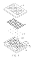
FIG. 7 is a schematic view showing an assembling stage of the assembling device of FIG. 1 in a first state.
FIG. 8 is a schematic view of an image sensor plate of a camera actuator used in the assembling stage.
FIG. 9 is a schematic view showing the assembling stage of the assembling device of FIG. 1 in a second state.
FIG. 10 is an enlarged view of a circular part X in FIG. 9.
DETAILED DESCRIPTION
FIGS. 1-6 show an assembling device 100 for a guide pole of a camera actuator according to an exemplary embodiment. The assembling device 100 includes a pedestal 10, a number of guide pole receiving units 20, a frame 30 and a cover 40. The pedestal 10, the guide pole receiving units 20, the frame 30 and the cover 40 are substantially cuboids.
The pedestal 10 includes a first surface 11 and a second surface 12 opposite to the first surface 11. The first surface 11 defines a number of first receiving holes 110. The first receiving hole 110 is a blind hole and includes a first cylindrical portion 113 and a first conical opening 111 connected with the first cylindrical bottom portion 113. The aperture of the first conical opening 111 gradually decreases from the first surface 11 to the second surface 12.
A magnet 112 is received in each of the first receiving holes 110. The magnet 112 is rod-shaped and a diameter of the magnet 112 is slightly less than a minimum diameter of the first receiving hole 110. The magnet 112 is fixed in the first receiving hole 110 by glue or adhesive. The second surface 12 has a number of first bumps 120. The first bump 120 spatially corresponds with the respective first receiving hole 110 and the first cylindrical portion 113 is aligned with the center of the first bump 120.
The frame 30 is mounted on the second surface 12. The frame 30 defines a number of through holes 301. Each through hole 301 spatially corresponds to the first bump 120 and the first bump 120 is received in the corresponding through hole 301. The frame 30 includes a first side surface 303 and a second side surface 304 opposite to the first side surface 303. The first side surface 303 defines a first recess 3031 and the second side surface 304 defines a second recess 3041 corresponding to the first recess 3031. The first recess 3031 and the second recess 3041 are configured for easily separating the cover 40 and the frame 30.
The second surface 12 of the pedestal 10 further defines five first fixing poles 115 at the edge of the second surface 12. The frame 30 defines a number of first fixing holes 302 surrounding the through hole 301. The frame 30 is fixed with the pedestal 10 through engaging the first fixing pole 115 in the first fixing hole 302.
The thickness of the frame 30 is larger than a sum of the thickness of guide pole receiving unit 20 and the thickness of the first bump 120, and each guide pole receiving unit 20 is received in the corresponding through hole 301 and stacked on the corresponding first bump 120. The first bump 120 and the guide pole receiving unit 20 have a substantially rectangular cross-section. Each first bump 120 includes a number of second fixing poles 121, and each guide pole receiving unit 20 further defines a number of first fixing holes 211. The second fixing pole 121 is engaged with the first fixing hole 211. The guide pole receiving unit 20 defines a second receiving hole 210 at a corner. The second receiving hole 210 is configured for receiving a guide pole 50 (shown in FIG. 7). The second receiving hole 210 extends through the guide pole receiving unit 20 and includes two conical opening portions and a circular cylinder potion interconnected between the two conical opening portions (shown in FIG. 3 and FIG. 4). The second receiving hole 210 can be designed to different sizes according to the size of the guide pole 50. So the guide pole receiving unit 20 is changeable according to the size of the guide pole 50.
The cover 40 is mounted on the frame 30 and includes a top surface 403 and a bottom surface 404 opposite to the top surface 403. The top surface 403 defines a number of dispensing holes 402. The dispensing hole 402 extends through the cover 40. The dispensing hole 402 corresponds aligned with the corresponding second receiving holes 210 and the second receiving hole 210 being exposed through the dispensing holes 402. The dispensing hole 402 includes a second conical opening 4021 and a second cylindrical portion 4022 connected with the second the conical opening 4021 (shown in FIG. 2). The bottom surface 404 of the cover 40 has a number of second bumps 4041. The second bumps 4041 correspond to the dispensing hole 402. The bottom surface 404 of the cover 40 includes a number of third fixing poles 401. The cover 40 is fixed with the frame 30 through engaging the third fixing pole 401 in the first fixing hole 302. A pre-determined spacing 4042 (shown in FIG. 5) is defined between the cover 40 and the guide pole receiving unit 20. The pre-determined spacing 4042 is configured for receiving an image sensor plate 60 (shown in FIG. 7).
FIGS. 7-10 show an assembling method using the assembling device 100. The assembling method includes the following steps.
Step S1: an assembling device 100, a number of guide poles 50 and a number of image sensor plates 60 are provided. The guide pole 50 is made of metal, such us iron, cobalt, nickel and other metals that can be magnetized by the magnet 110. A height of the guide pole 50 is larger than a thickness of the guide pole receiving unit 20. The image sensor plate 60 includes a bearing hole 61 configured for receiving one end of the guide pole 50.
Step S2: the cover 40 is removed from the frame 30.
Step S3: the guide pole 50 is put into the second receiving hole 210 and is exposed at a pre-determined thickness from the second receiving hole. The pre-determined thickness is a thickness of the image sensor plate 60. The guide pole 50 is kept a vertical state in the second receiving hole 210 because of being attracted by the magnet 112.
Step S4: the image sensor plate 60 is put on the guide pole receiving unit 20 and the guide pole 50 is inserted into the bearing hole 61.
Step S5: the cover 40 covers the frame 30. The image sensor plate 60 is located in the pre-spacing 4042 formed between the second bump 4041 and the guide pole receiving unit 20, and the bearing hole 61 is exposed from the dispensing hole 402.
Step S5: bonding material, such as glue or adhesive is dispersed into the dispensing hole 402, the bonding material flows to the bearing hole 61, and the bonding material is cured. In this way, the guide pole 50 is fixed with the image sensor plate 60. By using the assembling device 100 in this disclosure, the guide pole 50 is kept a vertical state in the second receiving hole 210. Therefore, the guide pole 50 is perpendicular to the image sensor plate 60 during an assembling process.
It is to be understood, however, that even though numerous characteristics and advantages of the present embodiments have been set forth in the foregoing description, together with details of the structures and functions of the embodiments, the disclosure is illustrative only, and changes may be made in detail, especially in the matters of shape, size, and arrangement of portion within the principles of the disclosure to the full extent indicated by the broad general meaning of the terms in which the appended claims are expressed.