US9545886B2 - Cargo tray assembly for a vehicle - Google Patents
Cargo tray assembly for a vehicle Download PDFInfo
- Publication number
- US9545886B2 US9545886B2 US14/136,558 US201314136558A US9545886B2 US 9545886 B2 US9545886 B2 US 9545886B2 US 201314136558 A US201314136558 A US 201314136558A US 9545886 B2 US9545886 B2 US 9545886B2
- Authority
- US
- United States
- Prior art keywords
- section
- tray
- cargo
- hinged
- planar section
- Prior art date
- Legal status (The legal status is an assumption and is not a legal conclusion. Google has not performed a legal analysis and makes no representation as to the accuracy of the status listed.)
- Expired - Fee Related, expires
Links
Images


Classifications
-
- B—PERFORMING OPERATIONS; TRANSPORTING
- B60—VEHICLES IN GENERAL
- B60R—VEHICLES, VEHICLE FITTINGS, OR VEHICLE PARTS, NOT OTHERWISE PROVIDED FOR
- B60R13/00—Elements for body-finishing, identifying, or decorating; Arrangements or adaptations for advertising purposes
- B60R13/01—Liners for load platforms or load compartments
- B60R13/011—Liners for load platforms or load compartments for internal load compartments, e.g. car trunks
-
- B—PERFORMING OPERATIONS; TRANSPORTING
- B60—VEHICLES IN GENERAL
- B60R—VEHICLES, VEHICLE FITTINGS, OR VEHICLE PARTS, NOT OTHERWISE PROVIDED FOR
- B60R5/00—Compartments within vehicle body primarily intended or sufficiently spacious for trunks, suit-cases, or the like
- B60R5/04—Compartments within vehicle body primarily intended or sufficiently spacious for trunks, suit-cases, or the like arranged at rear of vehicle
-
- B—PERFORMING OPERATIONS; TRANSPORTING
- B60—VEHICLES IN GENERAL
- B60R—VEHICLES, VEHICLE FITTINGS, OR VEHICLE PARTS, NOT OTHERWISE PROVIDED FOR
- B60R13/00—Elements for body-finishing, identifying, or decorating; Arrangements or adaptations for advertising purposes
- B60R13/01—Liners for load platforms or load compartments
- B60R13/011—Liners for load platforms or load compartments for internal load compartments, e.g. car trunks
- B60R13/013—Liners for load platforms or load compartments for internal load compartments, e.g. car trunks comprising removable or hinged parts, e.g. for accessing storage compartments
-
- B—PERFORMING OPERATIONS; TRANSPORTING
- B60—VEHICLES IN GENERAL
- B60R—VEHICLES, VEHICLE FITTINGS, OR VEHICLE PARTS, NOT OTHERWISE PROVIDED FOR
- B60R7/00—Stowing or holding appliances inside vehicle primarily intended for personal property smaller than suit-cases, e.g. travelling articles, or maps
- B60R7/02—Stowing or holding appliances inside vehicle primarily intended for personal property smaller than suit-cases, e.g. travelling articles, or maps in separate luggage compartment
Definitions
- the present disclosure relates to a cargo tray assembly for a vehicle.
- Modern sport utility vehicles, crossover vehicles, pickup trucks, and the like typically provide a row of one or more seats adjacent to a rear cargo area.
- the rear seats may be configured as traditional bench-style seats, 50/50 or 60/40 split bench-style seats, or individual bucket seats.
- the seats may be selectively adjusted to provide customized seat positioning and cargo area configuration. Possible seat adjustments may include seat fore/aft position, seat back recline angle, seat back fold flat for loading cargo on top of the seat back, etc.
- mats or trays may be used to keep dirt, spills, and sharp edges from contacting the materials covering the cargo area floor and the seats.
- existing vehicle cargo tray designs have certain design limitations, and as a result, may not fully protect the vehicle interior. This is particularly true when conventional trays are used with certain types of adjustable seats.
- a cargo tray assembly is disclosed herein for use in a vehicle interior.
- the cargo tray assembly includes first and second trays.
- the first tray has a translatable planar section, i.e., a horizontal/flat section that is moveable both forward and aft with respect to a first axis, which is typically a longitudinal axis or centerline of the vehicle.
- the translatable planar section is arranged along a first plane.
- the first tray also includes a first hinged section.
- the first hinged section is connected to the translatable planar section, e.g., via a living hinge, and pivots between an upright/orthogonal position and a flattened/parallel position, with the orientation of each position being with respect to the first plane, e.g., to a second axis such as a lateral axis of the vehicle.
- the second tray in this embodiment which is connected to or otherwise positioned with respect to the first tray, has a fixed planar section that is arranged along a second plane.
- the second plane is parallel to the first plane.
- the fixed planar section is connectable to the vehicle interior, such as to the walls or a floor of a cargo area of the vehicle interior.
- the first hinged section may also be connectable to the vehicle interior, for instance to an adjustable seat located within the vehicle interior.
- the translatable planar section is configured to translate with respect to the fixed planar section, for instance in response to an applied force to the seat when a passenger slides the seat forward or aft within the vehicle interior.
- the first hinged section is configured to pivot about an axis that is orthogonal to the direction of translation, such as when the seat is folded flat for increased cargo capacity.
- the first and/or the second tray may be thermoformed from a suitable thermoplastic material in a possible embodiment, e.g., polyurethane, or from metal, polypropylene, composite materials, or other suitable materials in other embodiments.
- the first hinged section may be connected to the translatable planar section, and the second hinged section may be connected to the fixed planar section, e.g., via a living hinge.
- shaped wall sections e.g., inverted arcuate or U-shaped wall sections, may be formed at one or more edges of the first and second trays. Such wall sections define a guide feature for translation of the translatable planar section.
- fasteners such as hook-and-loop fasteners may connect the first hinged section to the back of the seat(s). Alternatively, the fasteners may be snap-fit fasteners or other fastener designs.
- a vehicle having a body, an adjustable seat, and the cargo tray assembly noted above.
- the body defines the vehicle interior.
- the translatable planar section is configured to translate with respect to the fixed planar section in response to a translation of the adjustable seat along a first axis, e.g., when a passenger slides the seat forward or aft in the vehicle interior.
- the first hinged section pivots in conjunction with the seat whenever the seat is rotated about a second axis that is orthogonally arranged with respect to the first axis, such as when the seat is folded flat for stowing and/or for loading cargo, or moved into an upright position to provide a seating surface.
- FIG. 1 is a schematic perspective rear view of an example vehicle interior with a cargo tray assembly in an upright position.
- FIG. 1A is a schematic plan view illustration describing longitudinal and lateral axes of the vehicle of FIG. 1 .
- FIG. 2A is a schematic perspective side view illustration of part of the vehicle interior shown in FIG. 1 , with the seat translated to a rear position and folded flat.
- FIG. 2B is a schematic perspective side view illustration of the part of the vehicle interior shown in FIG. 2A , with the seat translated to a forward position and folded flat.
- FIG. 3 is a schematic perspective view illustration of an example embodiment of the disclosed cargo tray assembly in an upright position.
- FIG. 3A is a partial schematic cross-sectional side view illustration of the cargo tray assembly of FIG. 3 .
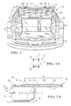
- FIG. 4 is a schematic perspective view illustration of the cargo tray assembly of FIG. 3 in a folded flat/flattened position.
- FIG. 4A is a partial schematic cross-sectional side view illustration of the cargo tray assembly of FIG. 4 .
- FIG. 4B is a schematic cross-sectional side view illustration of the cargo tray assembly of FIG. 4 .
- an example vehicle 10 includes a cargo tray assembly 26 in accordance with the present disclosure.
- the cargo tray assembly 26 of the present invention is configured to translate and pivot in conjunction with an adjustable seat 18 through a range of possible seating positions, including translated forward/aft, positioned upright, reclined, and folded flat/stowed. As described in detail below with reference to FIGS. 2A-4B , in all of these possible adjustable seating positions, the cargo tray assembly 26 maintains contact with the seat 18 to optimize protection of the vehicle interior 14 from dirt, sharp edges, and the like.
- the vehicle 10 which includes a vehicle body 12 defining the vehicle interior 14 , may be configured as a sport utility vehicle as shown, but other designs such as crossover vehicles, pickup trucks, or the like may also be used with the cargo tray assembly 26 described herein.
- the vehicle interior 14 which includes a cargo area 16 having a floor 20 , has an inner perimeter 21 surrounding the floor 20 .
- the seat 18 is shown as a rear row of seats, i.e., a row that is positioned immediately adjacent to the cargo area 16 .
- other designs may be contemplated which have the cargo area 16 adjacent to a different row of seats, e.g., a single front row of seats, and thus the positioning of the seat 18 can vary with the particular design of the vehicle 10 .
- adjustable means at least translatable, i.e., slidably moveable along one axis, and may also include rotation/pivoting about a second axis that is orthogonal to the first axis.
- Example axes A and B are described below with reference to FIG. 1A .
- the cargo tray assembly 26 of FIG. 1 is connectable to the vehicle interior 14 , such as to a cargo area floor 20 , to any of the walls or other structure defining the interior perimeter 21 , and/or to the seat 18 , so as to move in conjunction with the seat 18 in all possible seating positions. In this manner, the cargo area 16 remains fully covered by the cargo tray assembly 26 regardless of whether the seat 18 and the cargo tray assembly 26 are in an upright position as shown in FIGS. 3 and 3A or in a folded flat/flattened position as shown in FIGS. 2A, 2B, 4, and 4A .
- the vehicle 10 has a centerline or longitudinal axis A that extends lengthwise from a set of front wheels 11 F to a set of rear wheels 11 R in a typical configuration in which a driver is seated in proximity to the front wheels 11 F while passengers are seated behind the driver in closer proximity to the rear wheels 11 R.
- the vehicle 10 has a lateral axis B spanning the width of the vehicle 10 , with the lateral axis B arranged orthogonally with respect to the longitudinal axis A.
- any motion described as “translatable” herein can occur along longitudinal axis A, or along another axis that is parallel to the longitudinal axis A, while any motion described as “pivotable” can occur with respect to lateral axis B, or with respect to another axis that is parallel to the lateral axis B.
- the seat 18 which in a typical configuration would be positioned immediately adjacent to the cargo area 16 and attached to the body 12 , can be selectively positioned in a plurality of selectable positions along the longitudinal axis A of FIG. 1A .
- the seat 18 in some embodiments may include a first seat 18 A and a second seat 18 B as shown, a single seat, or additional seats without departing from the intended inventive scope. That is, the seat 18 may be a bench, 50/50 split, 60/40 split, bucket, or any other seat configuration.
- the seats 18 A, 18 B may be positioned in a plurality of selectable positions along the longitudinal axis A of FIG. 1A , either together or individually.
- the cargo area tray 26 of the present invention is intended to function with any of these seat configurations.
- the seat 18 of FIG. 1 also includes one or more seat backs 22 , which may include a first seat back 22 A and a second seat back 22 B in the two-seat embodiment of FIG. 1 .
- the seat backs 22 A, 22 B which collectively have an outer perimeter 29 , may be positioned in a plurality of selectable upright, reclined or flattened/folded flat positions relative to the lateral axis B of FIG. 1A , either together or individually.
- the seats backs 22 A, 22 B may include headrests 24 or other hardware without affecting the intended operation of the cargo tray assembly 26 .
- FIGS. 2A and 2B the seat 18 and the attached cargo tray assembly 26 of FIG. 1 are shown in a flattened/folded flat position, with FIG. 2A depicting the seat 18 in a first (rearward) translated position and FIG. 2B depicting the seat 18 in a second (forward) translated position.
- the cargo tray assembly 26 includes a first tray 28 and second tray 30 , with the second tray 30 positioned with respect to the first tray 28 .
- the first tray 28 includes a first hinged section 28 A and a translatable planar section 28 B, with a hinge 36 or other connecting feature disposed therebetween to operatively connect the first hinged section 28 A to the translatable planar section 28 B.
- the hinge 36 may be embodied as a living hinge, i.e., constructed by forming a narrow area of material in the first tray 28 , or it may be any other type of integral or separately attached hinge.
- the second tray 30 has a fixed planar section 30 B, and may also include a second hinged section 30 A.
- a second hinged section 30 A When the second hinged section 30 A is used, another hinge 38 or other connecting feature may be disposed between the second hinged section 30 A and the fixed planar section 30 B as shown.
- the hinge 38 as with the hinge 36 , may be embodied as a living hinge as described above.
- the translatable planar section 28 B is configured to translate with respect to the fixed planar section 30 B, e.g., in response to an applied force.
- a force (F 1 ) of FIG. 2A may be used to slide or otherwise translate the seat 18 in one direction, while an opposite force (F 2 ) of FIG. 2B may be applied to translate the seat 18 in the other direction, with any translation of the seat 18 likewise translating the connected translatable planar section 28 B.
- the first hinged section 28 A is thus configured to pivot or rotate about the hinge 36 orthogonally to the direction of translation.
- An intermediate area 23 of the vehicle interior 14 is located between the seat back 22 and the cargo area floor 20 .
- the intermediate area 23 includes a cabin floor 25 , which is generally parallel to the rear cargo area floor 20 but on a lower plane, i.e., a plane closer to the road surface (not shown) on which the vehicle 10 of FIG. 1 is travelling.
- the cargo tray assembly 26 of the present invention is thus intended to span, and thus fully cover, the cargo area floor 20 , the cabin floor 25 , and the seat backs 22 at all times.
- the cargo tray assembly 26 will now be described in further detail with reference to FIGS. 3 and 3A .
- FIGS. 3 and 3A both depict the cargo tray assembly 26 as it appears in an upright position, with FIG. 3A showing side detail of the cargo tray assembly 26 of FIG. 3 taken at line C-C.
- FIGS. 4 and 4A show the same cargo tray assembly 26 of FIGS. 3 and 3A in a folded flat/flattened position.
- the description of FIG. 3 therefore applies to FIG. 4 .
- the description of FIG. 3A applies to FIG. 4A .
- the structure of the cargo tray assembly 26 will be described primarily with reference to FIGS. 3 and 3A .
- the cargo tray assembly 26 of FIGS. 3 and 3A includes the respective first and second trays 28 and 30 as noted above.
- the cargo tray assembly 26 is bounded by a front edge 44 , a rear edge 46 , a left edge 48 , and a right edge 50 , with the terms “front”, “rear”, “left”, and “right” referring to the typical positions with respect to a forward-facing passenger of the vehicle 10 of FIG. 1 .
- the respective first and second trays 28 and 30 may be thermoformed of a suitable thermoplastic material, or formed of rubber, thermoset plastic, metal, or any other suitable material.
- the first tray 28 may include the first hinged section 28 A noted above, which is configured to connect to the seat back 22 of FIGS.
- the first hinged section 28 A when used is moveable anywhere between an upright position ( FIG. 3 ) and folded flat/flattened position ( FIG. 4 ).
- the first tray 28 also includes the translatable planar section 28 B, which may be attached to the first hinged section 28 A via the hinge 36 as noted above.
- the first hinged section 28 A may be optionally split into a left first hinged section 28 C and a right first hinged section 28 D adjacent to the hinge 36 , with “left” and “right” referring to the position of a forward-facing passenger within the vehicle interior 14 of FIG. 1 .
- the first hinged section 28 A may also include other first hinged sections.
- the respective left and right first hinged sections 28 C and 28 D may be configured to attach independently to each of the seat backs 22 A, 22 B of FIG. 1 to allow for independent translation of the seats 18 A, 18 B along the longitudinal axis A of FIG. 1A , and to allow for independent adjustment of the seat backs 22 A, 22 B relative to the lateral axis B of FIG. 1A .
- the fasteners 32 of FIG. 3 may be easily unfastened to facilitate removal of the cargo tray assembly 26 , or they may be configured as permanent fasteners.
- the fasteners 32 may be hook-and-loop type fasteners.
- the fasteners 32 may be a snap fit of an outer perimeter 35 of the first hinged sections 28 C, 28 D around the outer perimeter 29 (see FIG. 1 ) of the seat backs 22 A, 22 B of FIG. 1 .
- the fasteners 32 may be tabs (not shown) in the first hinged sections 28 C, 28 D that snap into slots (not shown) in the seat backs 22 A, 22 B of FIG. 1 .
- the one or more fasteners 32 may include one or more straps 52 , e.g., of elastic or other suitable material, that are attached to the first hinged sections 28 C, 28 D and looped around the headrests 24 of FIG. 1 . Any other suitable fastening method may also be used.
- the second tray 30 of FIG. 3 includes the fixed planar section 30 B noted above.
- the fixed planar section 30 B is stationary with respect to the cargo area floor 20 of FIGS. 2A and 2B and the translatable planar section 28 B in all of the selectable positions of the seat 18 and the seat back 22 of FIG. 1 .
- the fixed planar section 30 B may be fastened to the vehicle interior 14 , e.g., the cargo area floor 20 , for instance by one or more additional fasteners 34 .
- the additional fasteners 34 may be configured to be easily unfastened to facilitate removal of the cargo tray assembly 26 , or they may be configured as permanent fasteners.
- the additional fasteners 34 may be hook-and-loop type fasteners in an example embodiment.
- the additional fasteners 34 may include a close fit between an outer perimeter 33 of the fixed planar section 30 B and the inner perimeter 21 of the vehicle interior 14 (see FIG. 1 ).
- the additional fasteners 34 may include a snap fit of the outer perimeter 33 to the inner perimeter 21 of the interior 14 of FIG. 1 .
- the additional fasteners 34 may include tabs (not shown) in the second tray fixed planar section 30 B that snap fit into slots (not shown) in the cargo area floor 20 of FIGS. 2A and 2B . Any other suitable fastening method may also be used.
- Other embodiments may be envisioned for connecting the fixed planar section 30 B to the vehicle interior 14 of FIG. 1 , including for instance forming slots or grooves (not shown) in the vehicle interior 14 within which the fixed planar section 30 B can be inserted.
- FIGS. 4 and 4A are substantially identical to FIGS. 3 and 3A , but show respective FIGS. 3 and 3A in a folded flat/flattened seating position, i.e., when the seat backs 22 A, 22 B of FIG. 1 are in a folded flat or stowed position.
- the second hinged section 30 A of FIGS. 3 and 3A which may be attached to the fixed planar section 30 B by the hinge 38 , has a leading edge 31 .
- the second hinged section 30 A may be used to maintain contact with the first hinged section 28 A along the leading edge 31 , and to rotate in conjunction with first hinged section 28 A with respect to the lateral axis B of FIG. 1A whenever the seats 18 and the rear seat backs 22 of FIG. 1 pivot or rotate to selectively fold flat or deploy.
- Contact between the leading edge 31 of the second hinged section 30 A and the first hinged section 28 A may be maintained through both gravity and elastic spring forces resulting from the hinge 38 acting on the second hinged section 30 A. These forces act to urge the leading edge 31 of the second hinged section 30 A into contact with the first hinged section 28 A.
- Other types of spring forces may also be employed to maintain contact between the leading edge 31 of the second hinged section 30 A and the first hinged section 28 A.
- the second hinged section 30 A of FIG. 3 may be optionally split into a left second hinged section 30 C and a right second hinged section 30 D adjacent to the hinge 38 .
- the second hinged section 30 A may also include other second hinged sections.
- the second hinged sections 30 C, 30 D are configured to maintain contact with the first hinged sections 28 C, 28 D along the leading edge 31 , as well as to rotate in conjunction with first hinged sections 28 C, 28 D with respect to the lateral axis B of FIG. 1A when the seats 18 A, 18 B translate and the seat backs 22 A, 22 B of FIG. 1 pivot, as described above.
- FIG. 4B this Figure shows a cross-section of the cargo tray assembly 26 of FIG. 4 taken at line E-E of FIG. 4 .
- the cargo tray assembly 26 may include a guide feature 54 that may be used to operatively connect the second tray 30 of FIG. 4A to the first tray 28 .
- wall sections 40 , 42 may be suitably shaped, e.g., as inverted U-shaped walls as shown, arcuate walls, circular walls, etc., to provide parallel guide channels 49 , such that the translatable planar section 28 B can slide back and forth within the guide channels 49 .
- Comparable guide features 54 may be envisioned such as slots, rails, grooves, or the like, whether singular or plural, and whether formed in the first and/or second trays 28 , 30 of FIG. 4A or in the structure of the vehicle interior 14 of FIG. 1 .
- Such wall sections 40 , 42 may be optionally formed on some or all of the edges 44 , 46 , 48 , 50 of the respective first and second trays 28 and 30 , with edges 44 and 46 shown in FIG. 3 .
- Other walls similar to the inverted U-shaped or arcuate wall sections shown, may be formed on other edges of the first and second trays 28 , 30 , including the edges between the first hinged sections 28 C, 28 D and the second hinged sections 30 C, 30 D of FIG. 3 .
- the example wall sections 40 , 42 of FIG. 4B may be formed by thermoforming, molding, or any other suitable forming process.
- the fixed section 30 B may also include optional mounting feet 60 , e.g., arcuate or U-shaped shaped feet opening away from the longitudinal axis A of FIG. 1A as shown. Some of the additional fasteners 34 may be attached to the feet 60 as shown, or the feet 60 may be snapped into or received within a channel (not shown) defined in the cargo area floor 20 of FIG. 1 . Other approaches to securing the cargo tray assembly 26 to the vehicle interior 14 of FIG.
- extending ends 61 of the feet 60 may be envisioned without departing from the intended inventive scope, e.g., extending ends 61 of the feet 60 to provide a radial tab which can be received in mating slots (not shown) in the vehicle interior 14 , or dispensing with the feet 60 and instead extending the wall section 42 such that the wall section 42 serves the same purpose, e.g., by being received into mating slots (not shown) in the vehicle interior 14 .
- the cargo tray assembly 26 as described above may have various other embodiments without departing from the intended inventive scope.
- relative positioning of the first and second trays 28 and 30 , respectively can be reversed such that that second tray 30 lies below the first tray 28 with respect to the typical orientation of the vehicle interior 14 . That is, as shown in FIG. 4A , the second tray 30 remains fixed above the first tray 28 . This may be reversed without changing the resultant benefits.
- the second hinged section 30 A and the hinge 38 may be eliminated, such that the second hinged section 30 A effectively becomes an extension of the fixed planar section 30 B.
- other connection mechanisms may be envisioned for allowing the first tray 28 to translate with respect to the second tray 30 . While the design of FIG. 4B is one possible example, others may include devices such as rollers, wheels, tongue-and-groove, and the like. Thus, the example embodiments set forth above are not intended to be limiting, but rather are examples of suitable configurations.
Landscapes
- Engineering & Computer Science (AREA)
- Mechanical Engineering (AREA)
- Vehicle Step Arrangements And Article Storage (AREA)
Abstract
Description
Claims (20)
Priority Applications (3)
| Application Number | Priority Date | Filing Date | Title |
|---|---|---|---|
| US14/136,558 US9545886B2 (en) | 2013-12-20 | 2013-12-20 | Cargo tray assembly for a vehicle |
| CN201410655739.6A CN104723970B (en) | 2013-12-20 | 2014-11-18 | For the goods blade assemblies of vehicle |
| DE102014118864.0A DE102014118864B4 (en) | 2013-12-20 | 2014-12-17 | Load storage arrangement for a vehicle |
Applications Claiming Priority (1)
| Application Number | Priority Date | Filing Date | Title |
|---|---|---|---|
| US14/136,558 US9545886B2 (en) | 2013-12-20 | 2013-12-20 | Cargo tray assembly for a vehicle |
Publications (2)
| Publication Number | Publication Date |
|---|---|
| US20150175090A1 US20150175090A1 (en) | 2015-06-25 |
| US9545886B2 true US9545886B2 (en) | 2017-01-17 |
Family
ID=53275512
Family Applications (1)
| Application Number | Title | Priority Date | Filing Date |
|---|---|---|---|
| US14/136,558 Expired - Fee Related US9545886B2 (en) | 2013-12-20 | 2013-12-20 | Cargo tray assembly for a vehicle |
Country Status (3)
| Country | Link |
|---|---|
| US (1) | US9545886B2 (en) |
| CN (1) | CN104723970B (en) |
| DE (1) | DE102014118864B4 (en) |
Cited By (2)
| Publication number | Priority date | Publication date | Assignee | Title |
|---|---|---|---|---|
| US11135952B2 (en) * | 2017-07-14 | 2021-10-05 | 4Knines, LLC | Cover adaptable to foldable vehicle seats |
| US12397686B2 (en) * | 2022-11-29 | 2025-08-26 | Hyundai Motor Company | Full-flat rear seat |
Families Citing this family (6)
| Publication number | Priority date | Publication date | Assignee | Title |
|---|---|---|---|---|
| US10160381B1 (en) * | 2017-08-11 | 2018-12-25 | GM Global Technology Operations LLC | Vehicle cargo canopy with hazard warning sign |
| DE102018208704A1 (en) | 2018-06-01 | 2019-12-05 | Volkswagen Aktiengesellschaft | Protective device for the at least partial protection of a motor vehicle load compartment and motor vehicle |
| JP7408094B2 (en) * | 2020-04-27 | 2024-01-05 | キョーラク株式会社 | Structure |
| CN112124219B (en) * | 2020-10-13 | 2022-03-15 | 江苏瀚皋机械有限公司 | Full-automatic soft-wrapping edge structure of automobile trunk cover plate |
| DE102020128581A1 (en) | 2020-10-30 | 2022-05-05 | Pfanner Schutzbekleidung Gmbh | Partition wall system for an interior of a vehicle |
| US12479347B2 (en) * | 2022-10-12 | 2025-11-25 | Macneil Ip Llc | Hinged cargo liner |
Citations (7)
| Publication number | Priority date | Publication date | Assignee | Title |
|---|---|---|---|---|
| US5322335A (en) * | 1993-08-30 | 1994-06-21 | Penda Corporation | Automotive floor liner |
| US5716091A (en) * | 1996-05-20 | 1998-02-10 | Irvin Automotive Products, Inc. | Flipper panel with storage bin |
| DE10012590A1 (en) | 2000-03-15 | 2001-09-20 | Opel Adam Ag | Seating arrangement in front of the luggage compartment of a vehicle |
| CN1490200A (en) | 2002-09-04 | 2004-04-21 | 本田技研工业株式会社 | vehicle rear structure |
| DE202005007157U1 (en) | 2005-05-02 | 2005-07-07 | Carcoustics Tech Center Gmbh | Vehicle load space floor consists of at least one hollow plastic panel made up of panel sections joined to one another via a strip with a triangular cross section and film hinges |
| US8186736B2 (en) * | 2007-03-28 | 2012-05-29 | Meiwa Industry Co., Ltd. | Hinge mechanism and automotive luggage board structure using the same |
| US20130147226A1 (en) * | 2011-12-09 | 2013-06-13 | Honda Motor Co., Ltd. | Cargo cover for movable seat |
-
2013
- 2013-12-20 US US14/136,558 patent/US9545886B2/en not_active Expired - Fee Related
-
2014
- 2014-11-18 CN CN201410655739.6A patent/CN104723970B/en not_active Expired - Fee Related
- 2014-12-17 DE DE102014118864.0A patent/DE102014118864B4/en not_active Expired - Fee Related
Patent Citations (7)
| Publication number | Priority date | Publication date | Assignee | Title |
|---|---|---|---|---|
| US5322335A (en) * | 1993-08-30 | 1994-06-21 | Penda Corporation | Automotive floor liner |
| US5716091A (en) * | 1996-05-20 | 1998-02-10 | Irvin Automotive Products, Inc. | Flipper panel with storage bin |
| DE10012590A1 (en) | 2000-03-15 | 2001-09-20 | Opel Adam Ag | Seating arrangement in front of the luggage compartment of a vehicle |
| CN1490200A (en) | 2002-09-04 | 2004-04-21 | 本田技研工业株式会社 | vehicle rear structure |
| DE202005007157U1 (en) | 2005-05-02 | 2005-07-07 | Carcoustics Tech Center Gmbh | Vehicle load space floor consists of at least one hollow plastic panel made up of panel sections joined to one another via a strip with a triangular cross section and film hinges |
| US8186736B2 (en) * | 2007-03-28 | 2012-05-29 | Meiwa Industry Co., Ltd. | Hinge mechanism and automotive luggage board structure using the same |
| US20130147226A1 (en) * | 2011-12-09 | 2013-06-13 | Honda Motor Co., Ltd. | Cargo cover for movable seat |
Cited By (3)
| Publication number | Priority date | Publication date | Assignee | Title |
|---|---|---|---|---|
| US11135952B2 (en) * | 2017-07-14 | 2021-10-05 | 4Knines, LLC | Cover adaptable to foldable vehicle seats |
| US11535132B2 (en) | 2017-07-14 | 2022-12-27 | 4Knines, LLC | Cover adaptable to foldable vehicle seats |
| US12397686B2 (en) * | 2022-11-29 | 2025-08-26 | Hyundai Motor Company | Full-flat rear seat |
Also Published As
| Publication number | Publication date |
|---|---|
| DE102014118864A1 (en) | 2015-06-25 |
| CN104723970B (en) | 2017-06-23 |
| US20150175090A1 (en) | 2015-06-25 |
| DE102014118864B4 (en) | 2019-08-22 |
| CN104723970A (en) | 2015-06-24 |
Similar Documents
| Publication | Publication Date | Title |
|---|---|---|
| US9545886B2 (en) | Cargo tray assembly for a vehicle | |
| US9616776B1 (en) | Integrated power thigh extender | |
| US7416235B2 (en) | Dual sliding center console | |
| US9199564B2 (en) | Seat assembly having a trim cover assembly | |
| US8152231B2 (en) | Collapsible seat and system | |
| US9187012B2 (en) | Pivoting and reclining vehicle seating assembly | |
| US10286818B2 (en) | Dual suspension seating assembly | |
| US6234553B1 (en) | Flexible seat system | |
| US8936301B2 (en) | Vehicle load floor assembly for a seatback | |
| US7510227B2 (en) | Vehicle rear seat | |
| US20090058154A1 (en) | Vehicle seat assembly | |
| US11472377B2 (en) | Integrated vacuum for motor vehicle | |
| US9821683B2 (en) | Easy seat positioning and installation | |
| US9126543B1 (en) | Vehicle interior structure | |
| US20080216718A1 (en) | Loading base arrangement | |
| US6820913B2 (en) | Convertible seat assembly with cross-vehicle support | |
| US9694755B2 (en) | Seat assembly with removable cushion insert | |
| US7976093B2 (en) | Cantilevered seat for a vehicle | |
| CN103241149B (en) | Motor vehicle with a backrest seat | |
| US20130187400A1 (en) | Reconfigurable console assembly and method of assembling the same | |
| GB2592940A (en) | Bulkhead for a vehicle | |
| US20170297458A1 (en) | Vehicle seat adjustment system | |
| US9381884B2 (en) | Vehicle seat | |
| US10843612B1 (en) | Leg support system for seating assembly | |
| CN113696799A (en) | Transverse translation seat pedestal |
Legal Events
| Date | Code | Title | Description |
|---|---|---|---|
| AS | Assignment |
Owner name: GM GLOBAL TECHNOLOGY OPERATIONS LLC, MICHIGAN Free format text: ASSIGNMENT OF ASSIGNORS INTEREST;ASSIGNOR:HA, WING;REEL/FRAME:032314/0989 Effective date: 20131216 |
|
| AS | Assignment |
Owner name: WILMINGTON TRUST COMPANY, DELAWARE Free format text: SECURITY INTEREST;ASSIGNOR:GM GLOBAL TECHNOLOGY OPERATIONS LLC;REEL/FRAME:033135/0440 Effective date: 20101027 |
|
| AS | Assignment |
Owner name: GM GLOBAL TECHNOLOGY OPERATIONS LLC, MICHIGAN Free format text: RELEASE BY SECURED PARTY;ASSIGNOR:WILMINGTON TRUST COMPANY;REEL/FRAME:034189/0065 Effective date: 20141017 |
|
| FEPP | Fee payment procedure |
Free format text: PAYOR NUMBER ASSIGNED (ORIGINAL EVENT CODE: ASPN); ENTITY STATUS OF PATENT OWNER: LARGE ENTITY |
|
| STCF | Information on status: patent grant |
Free format text: PATENTED CASE |
|
| FEPP | Fee payment procedure |
Free format text: MAINTENANCE FEE REMINDER MAILED (ORIGINAL EVENT CODE: REM.); ENTITY STATUS OF PATENT OWNER: LARGE ENTITY |
|
| LAPS | Lapse for failure to pay maintenance fees |
Free format text: PATENT EXPIRED FOR FAILURE TO PAY MAINTENANCE FEES (ORIGINAL EVENT CODE: EXP.); ENTITY STATUS OF PATENT OWNER: LARGE ENTITY |
|
| STCH | Information on status: patent discontinuation |
Free format text: PATENT EXPIRED DUE TO NONPAYMENT OF MAINTENANCE FEES UNDER 37 CFR 1.362 |
|
| FP | Lapsed due to failure to pay maintenance fee |
Effective date: 20210117 |