US954409A - Railroad-rail anchor. - Google Patents
Railroad-rail anchor. Download PDFInfo
- Publication number
- US954409A US954409A US50302006A US1906503020A US954409A US 954409 A US954409 A US 954409A US 50302006 A US50302006 A US 50302006A US 1906503020 A US1906503020 A US 1906503020A US 954409 A US954409 A US 954409A
- Authority
- US
- United States
- Prior art keywords
- rail
- tie
- plate
- flange
- lug
- Prior art date
- Legal status (The legal status is an assumption and is not a legal conclusion. Google has not performed a legal analysis and makes no representation as to the accuracy of the status listed.)
- Expired - Lifetime
Links
- 238000010276 construction Methods 0.000 description 36
- 238000004873 anchoring Methods 0.000 description 17
- 238000005266 casting Methods 0.000 description 6
- 241001661918 Bartonia Species 0.000 description 3
- 230000004048 modification Effects 0.000 description 3
- 238000012986 modification Methods 0.000 description 3
- XEEYBQQBJWHFJM-UHFFFAOYSA-N Iron Chemical compound [Fe] XEEYBQQBJWHFJM-UHFFFAOYSA-N 0.000 description 2
- 238000006073 displacement reaction Methods 0.000 description 2
- 230000000694 effects Effects 0.000 description 2
- 238000005242 forging Methods 0.000 description 2
- 239000002023 wood Substances 0.000 description 2
- 229910000831 Steel Inorganic materials 0.000 description 1
- 230000003467 diminishing effect Effects 0.000 description 1
- 239000000835 fiber Substances 0.000 description 1
- 230000000977 initiatory effect Effects 0.000 description 1
- 229910052742 iron Inorganic materials 0.000 description 1
- 239000000463 material Substances 0.000 description 1
- 239000002184 metal Substances 0.000 description 1
- 229910052751 metal Inorganic materials 0.000 description 1
- OXCMYAYHXIHQOA-UHFFFAOYSA-N potassium;[2-butyl-5-chloro-3-[[4-[2-(1,2,4-triaza-3-azanidacyclopenta-1,4-dien-5-yl)phenyl]phenyl]methyl]imidazol-4-yl]methanol Chemical compound [K+].CCCCC1=NC(Cl)=C(CO)N1CC1=CC=C(C=2C(=CC=CC=2)C2=N[N-]N=N2)C=C1 OXCMYAYHXIHQOA-UHFFFAOYSA-N 0.000 description 1
- 238000004904 shortening Methods 0.000 description 1
- 239000010959 steel Substances 0.000 description 1
- 238000005728 strengthening Methods 0.000 description 1
Images
Classifications
-
- E—FIXED CONSTRUCTIONS
- E01—CONSTRUCTION OF ROADS, RAILWAYS, OR BRIDGES
- E01B—PERMANENT WAY; PERMANENT-WAY TOOLS; MACHINES FOR MAKING RAILWAYS OF ALL KINDS
- E01B13/00—Arrangements preventing shifting of the track
- E01B13/02—Rail anchors
Definitions
- My invention relates to a novel, combined construction of tie-plate and rail anchoring device, so arranged and disposed as to act cooperatively upon the base flange of the rail, and with the initial application of the same to effectually anchor the rail against longitudinal or creeping movement; that is to say: my device when completely applied will not permit the rail to start to creep ⁇ and does not require any subsequent slight creeping movement of the rail in order to secure the maximum resisting elliciency of the construction, as, to the best of my knowledge is universally required in order to render thoroughly effective the prevailing types and constructions of rail anchors and antiereepers.
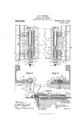
- z- Figure 1 is a plan view of my tieplate rail anchor, showing the same secured to the tie and rail with the ordinary driven tie-spikes.
- Fig. 2 is an end elevation of Fig. 1.
- Fig. 3 is a plan view similar to Fig. 1, but showing the construction secured to the tie with screw spikes, and showing also a right-hand anchor when relatively compared with Fig. 1 considered as a left-hand anchor.
- Fig. 4 is a cross-section taken on line -x of Fig. 3.
- Fig. 5 is a longitudinal section taken on line i/y of Fig. 1.
- G is a transverse section taken throughout the entire length of the double-flanged tie plate, on line o o of Fig. 1.
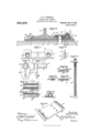
- Fig. 7 is a detail plan of the cap cover casting.
- Fig. 8 is an end elevation of the same.
- Figs. 9 and 10 are respectively detail end and side elevations of t-he sleeved depending lug.
- Figs. 11 and 12 are respectively a detail plan View and a side elevation of the sleeved tightening wedge.
- Fig. 13 is a cross-section of the same taken on the line Susi of Figs. 11 and 12.
- Figs. 14 and 15 are respectively a detail plan View and a side elevation of the locking wedge.
- Fig. 16 is a cross section of the same, taken on line R-R of Figs. 14 and 15.
- Fig. 17 is a side elevation of the longitudinally disposed interlocking standard bolt, being fitted with a nut locking washer.
- Fig. 1S is an isometric projection showing the double flanged yoking tie plate
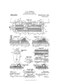
- Fig. 19 is a plan view of an alternative construction of my tie plate rail anchor, in which the tightening and lockingwedges are interlocked and the sleeved members disposed in direct engagement with the securing spikes, thereby simplifying the construction by dispensing with the cap cover casting.
- Fig. 20 is a cross section taken on line O O of Fig. 19.
- Fig. 21 is a cross section taken on line PP of Fig. 19.
- Figs. 22 and 23 are respectively a detail plan view and a side elevation of the flanged, interlocking, sleeved, tightening wedge.
- Fig. 24 is an end elevationV of the same.
- Fig. 25 Vis a detail end elevation of the sleeved depending lug.
- Figs. 26 and 27 show modified details whereby the tightening and locking wedges may be interlocked, dispensing with the overlapping, interlocking ⁇ flange shown in Figs. 22, 23 and 24.
- Figs. 2S and 29 are respectively detail plan and side elevations of the locking wedge adapted to cooperate wit-h the flanged interlocking tightening wedge.
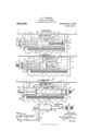
- Fig. 33 is a side elevation of the drop-forged depending lug and integrally formed sleeve stem with actuating adj usting nut used in the modified construction shown in plan in Fig. 32.
- A represents a Wood railway tie, suitably mounted upon which, and carrying the T-head rail B, is a tie plate C, which when used in conjunction with my rail-anchoring construction affords in addition to the usual tie-plate rail supporting function, that of a rail anchor supporting and retaining yoke plate.
- the tie plate C is designed to be of sufficient length to afford a space between the interlocking flange C2 and the adjacent inner edge B2 of the rail base, within and upon which to suitably mount and secure theseY parts.
- the entire construction including ⁇ the tie plate and rail anchor parts is designed to be secured upon the tie, adjacent the base flange of the rail by the use of the usual driven spikes B3 B3, as shown in Figs. 1, 2, 5, 6, 19, 2O and 21, or if preferred, by the use of screw spikes B4, as shown in Figs. 3 and 4.
- a cap cover casting D Suitably secured by the spikes, abutting and overlapping the inner edge B2 of the rail base is a cap cover casting D, having spike holes cl2 disposed adjacent the ends of the same and designed to register, when placed in position against the rail base with spike holes c4 c4 formed in the tie plate C.
- the connecting arched portion Z3 of this cover casting forms between the end lugs an elongated recess (lf.
- angular interlocking ⁇ faces Z5 Z5 are formed upon the sides of the end lugs, which form in conjunction with the angular interlocking face c3 of the tie plate flange C2 the runway or groove within which are mounted a flanged, sleeved tightening wedge E and a sleeved, tie-abutting, depending lug F, both of which parts are designed to have therein a limited amount of free longitudinal movement, in a plane parallel to the central longitudinal plan of the rail B.
- An elongated locking wedge G has formed upon the one edge thereof a suitable number of' teeth or serrations g2 and upon the opposite edge a bearing face g3, suitably angularly disposed with relation to the plane of' the serrated face g2, and when the construction is assembled is designed ⁇ to register when in engagement with the bearing face ci of the tightening wedge E.
- the tie plate C is secured under the rail B in proper position by the central spike B3 driven adjacent the tie plate flange C1, securing the outer rail base flange B1, as shown in Fig. 6.
- the longitudinal creep of' the rail is supposed to be in the direction indicated by the arrows shown upon the heads thereof.
- the locking wedge G is placed upon the tie plate C with the serrated edge g2 adjacent the base flange edge B2 of the rail B, at any point approximately midway between the tie plate spike holes o* c".
- the sleeved tightening wedge E is placed upon the tie plate C in engagement with the flange C2, the tightening wedge 64 being disposed adjacent the locking wedge Cr, and is moved along the flange C2 bringing its angular face e5 into engage ment with the angular face g3 of the locking wedge, in which position, as shown in broken lines in the figures, the wedges are disposed within the area of the elongated recess (Z4 of the cap cover casting D, which cover is placed over the same in position overlapping the base flange B2 of the rail B, and with the spike holes cl2 Z2 thereof placed in vertical alinement with the spike holes o4 c* of the tie plate.
- the sleeved end f ot' the depending lug F is inserted between the cap cover angular guide face (Z5 and the flange C2.
- the bolt H is inserted in the tightening wedge sleeve c and in the depending lug sleeve f3.
- the nut H3 is then applied and given a few turns to establish merely slight tension of the parts.
- the spikes B3 B3 are now driven home, securing alike the tie plate C, the rail B and the cap covering D overlapping the base flange B2 of the rail. Sufficient clearance is given the sleeve members between the tie plate flange C2 and the cap covering D to avoid extreme clamping or binding of the parts by accidental canting in the driving of the spikes.
- a maximum degree of initial, tensional application oli' the locking wedge is thus secured by a 'few turns of the bolt nut ll, seated against the depending lug hub f* and which takes resisting anchorage or bearing upon and against the side of the tie A through the depending, abutting flange fr', this tensional force being expended in a plane parallel to the central longitudinal plane of the rail B, and in direct opposition to the creeping movement of the same, and which force can be constantly maintained to a maximum degree by subsequent partial tightening rotation of' the nut H3. Constant active locking efficiency and stability of the cooperative construction is secured and maintained by the transversely disposed yoking efficiency and extended bearing area of the double flanged tie plate.
- FIG. 1S An alternative and somewhat simplified construction of my tie plate rail anchor is shown in Figs. 1S) to 2t), both inclusive, in which the cap covering l) is dispensed with, the spikes B- being driven through the tie plate spike holes cc-, as in ordinary practice into direct engagement with the base flange B2 of the rail B. rlhe sleeved menibers E.
- the locking wedge Gr ofI slightly modified detail design is iuterlocked in the engaged position with the tighteninfr wedge /2- andthe rail base flange B against accidental or malicious tampering displacenient by a transversely projecting, overlapping flange cformed upon the wedged side of the forward end of the sleeve c-3, as clearly shown in Figs. 19 and 21.
- rIhis locking wedge Gr is further secured against displacement by a longitudinal projection g-f formed upon the wider end of the wedge and designed to abut against the adjacent spike B-.
- the operation of installing this construction is materially simplified and facilitated as compared with the cap cover construction, and the parts being more compactly arranged, are fully as eflicient and reliable, and also afford a material saving in the shortening of the tie plate.
- Figs. 30, 31, 82 and 33 Additional modifications in the construction vof the detail parts of my tie plate rail anchor, but embodying the same novel functional features and constructive principle are shown in Figs. 30, 31, 82 and 33.
- the cap cover is designed to be used upon each, but the same is removed from all to more clearly show the detail operative parts. It will be understood also that with slightly modified details these several constructions can be used without the cap covering, substantially as shown in the modification and arrangement in Fig. 19.
- Fig. 30 the nut is dispensed with, a threaded bolt H only being used, which is inserted first lthrough the depending lug F and then screwed into the threaded sleeve e-SX of the tightening wedge E.
- Fig. 30 the nut is dispensed with, a threaded bolt H only being used, which is inserted first lthrough the depending lug F and then screwed into the threaded sleeve e-SX of the tightening wedge E.
- the integrally formed tightening wedge I and screw stem 3 -5 is preferably a drop forging.
- This construction affords a reduced number of detail parts.
- the tie abutting, integrally formed, depending lug K, with angular flange /cand screw stem k-S kP is preferably a drop forging.
- the extended leverage of the integrally formed screw stem affords, in the depending lug /c-5 maximum stability and transverse sectional strength, with simplicity of construction and a reduced number of detail parts.
- the sleeved members and cap covering are made preferably of malleable castings, and the locking wedges of hardened iron or steel.
- a tie-plate forming a support for the rail, adapted to be secured to the tie and having a flange on one end thereof, adapted to engage the base of the rail on one side, and an auxiliary flange upon Ithe opposite end thereof, a locking member interposed bet-Ween the base of the rail and the auxiliary flange, a tie-abutting depending lug and adjusting means connecting the lug and the said locking member, whereby the initial force expended upon the locking member effectually locks the rail against creeping movement.
- a tie-plate engaged by the rail and adapted to be secured to the tie, said plate having a flange adapted to engage the rail on one side, and an auxiliary flange, a wedge-shaped locking member interposed between the rail and the auxiliary flange, a tie-abutting depending lug and an adjust-ing device connecting the said lug with the locking member, whereby the initial force expended upon the locking member of the anchoring device eifectually locks the rail against creeping movement without depending upon the subsequent rail creeping movement to effect the locking function.
- a tie-plate forming a support for the rail, and adapted to be secured to the tie, the said plate having a flange upon one end there-of, adapted to engage one side of the rail, and an auxiliary flange upon the opposite end thereof, two cooperating locking members interposed between the fiange of the rail and the auxiliary tie-plate flange, a tie-abutting depending lug, and an adjusting bolt connecting the said lug and one o-f the locking members, the said bolt extending parallel with the rail, whereby the initial fo-rce expended upon the locking member effectually locks t t-he rail against creeping movement, without depending upon the subsequent creeping movement to effect the interlocking function.
- a tie-plate forming a support for the rail, the said plate being adap-ted to be secured to the tie and having a flange on one end arranged to engage the base flange of the rail on one side, the said plate also having an auxiliary flange upon its opposite end, two cooperating locking members interposed etween the base fiange of the rail and the auxiliary fiange of the tie-plate, one of the said locking members having a sleeve, a tieabutting depending lug and an adjusting bolt connecting the said lug and the sleeved locking member, whereby the initial force expended upon the locking members positively locks the rails against creeping movement, substantially as described.
- a tieplate forming a support .'t'or the rail, the said plate being' adapted to be made fastlo the tie and having flanges upon opposite ends thereof, one of' the said flanges being adapted to engage the base flange of the rail on one side, two wedge-shaped cooperating locking members, interposed between the rail flange and the tie-plate flange on the opposite side of' the rail, a tie-abutting, depending lug and a bolt connecting the said lug and one of' the said locking members, substantially as described.
- a rail anchor the combination of a tie-plate upon which the rail rests, the said plate being adapted to be made fast to the tie and provided with flanges upon opposite ends thereof', one of' said flanges being adapted to engage the base flange of the rail on ⁇ one side, two locking members interposed between the other flange of the tie-plate and the flange of the rail, one of the locking members having a toothed edge adapted to engage the rail flange, a tie-abutting depending lug, and a bolt for connecting one of the locking members with the said lug.
- a tie-plate forming a slipport for the rail, and having spike holes whereby it is adapted to be secured to the tie
- the said plate having flanges on opposite ends thereof, one of the said flanges being adapted to engage the base flange of the rail on one side, two cooperating locking members interposed between the rail flange and the tie-plate flange on the opposite side, one of the said locking members having a sleeve and an integral flange overlapping the other locking member, a tie-abutting depending lug, having a sleeve, the sleeve of the lng and the sleeve of the said locking member having flanges adapted to be engaged by the securing spikes passed through the holes in the tie-plate, and a bolt for connecting the tie-abutting lug and the sleeved locking member, the bolt passing through the sleeves of the lug and locking member, substantially as described.
- a rail anchor In a rail anchor, the combination of a tie-plate upon which the rail is adapted to rest, the said plate being adapted to be made fast to the tie and having flanges upon opposite ends, one of the said flanges being adapted to engage the base flange of the rail, two cooperating locking members interposed between the rail flange and the tie-plate flange on the opposite side, one of the said lockino' members having a sleeve, a tie-abutting depending sleeved lug and a bolt connecting the said lug and the sleeved locking member, the bolt passing through the sleeves of the connected parts and extending parallel with the rail for the purpose set forth.
- a tie-plate forming a support for the rail, the said plate being adapted to be made fast to the tie and having flanges upon opposite ends thereof', one of said flanges being adapted to engage the base flange of the ail on one side, two wedge-shaped, coperating locking members interposed between the rail flange and the tie-plate flange on the opposite side, the said members having interlocking adjacent edges, a tie-abutting, depending lug and adjusting means for connecting the said lug with one of the coperating locking members.
- a rail anchor comprising a tie-plate, upon which the rail is aeapted to rest, and having spike holes, whereby it is adapted to be secured to the tie, the said plate having flanges on opposite ends thereof, one of the said flanges being adapted to engage the base flange on one side, two wedge-shaped locking members, interposed between the rail flange and the tie-plate flange on the opposite side, one of the said locking members having a sleeve and a laterally projecting member, adapted to overlap the other locking member, the last named locking member having an extension adapted to engage the side of one of the securing spikes, a depending tie-abutting lug, provided with a sleeve, the sleeve of the lug and the sleeve of the locking member having longitudinally disposed flanges adapted to be engaged by tle securing spikes when passed through the holes of the tie-plate, substantially as described.
- a tie plate forming a support for the rail, adapted to be secured to the tie and having a flange on one end thereof, adapted to engage the base of the rail on one side.
- a locking member interposed between the base of the rail and the opposite end of the tie plate, at-ie abutting, depending lug, adjust-ing means connecting the lug and t-he said locking member, whereby the initial force expended upon the locking member effectually locks the rail against creeping movement, and means for securing the locking member in place upon the tie plate and engaging the locking member on the side opposite its engagement with the base of t-he rail.
- a tie-plate forming a support for the rail, means for securing the tie-plate to the tie, said means engaging the base of the rail on one side, and a locking member suitably mounted upon the tie-plate and adapted to engage the base of the rail on the opposite side, a tie-abutting lug and adjusting means connecting the lug and the said locking member.
- a rail anchor the combination of a rail, a tie-plate, a rail-anchoring member movably mounted on the tie-plate in engagement with the base of the rail on one side, a tie-abutting lug and adjusting means connecting the lug with the rail-anchoring member.
- a tie-plate-rail-anchor the combination of a tie, a tie-plate secured thereto and adapted to support the rail, a rail-anchoring device, suitably mounted on the tie-plate in engagement with the base flange of the rail, a tie-abutting lug, adjusting devices connecting the ra il-anchoring device and said lug, and actuated in a line parallel to the longitudinal plane ⁇ of the rail, to lock the rail againstlongitudinal movement.
Landscapes
- Engineering & Computer Science (AREA)
- Mechanical Engineering (AREA)
- Architecture (AREA)
- Civil Engineering (AREA)
- Structural Engineering (AREA)
- Joining Of Building Structures In Genera (AREA)
Description
D. H. POREMAN.
RAILROAD RAIL ANCHOR.
APPLIUATION FILED JUNE 18. 1909.
4 SHEETS-SHEET 1.
@wi/immo@ GMM/mm3 D. H. FOREMAN.
RAILROAD rRAIL ANGHOR.
APPLIGATION FILED JUNI: 1a. 1909.
Patented Apr. 5, 1910.
4 SHEETS-SHEET 2.
g1/nemica l1'. Foreman,
@www
MOT/14 D. H. FOREMAN.
RAILROAD RAIL ANCHOR.
ArPLIoATloN FILED JUNE 1s. 1909.
954,409. Patented Apr.5, 1910.
4 SHEETS-SHEET 3.
@wooda/tof, @mime/.awo QH Fore/77a n,
www Ef f5; @WMM 314247 WMM 'mismas-Essais.
D. H. POREMAN.
RAILROAD RAIL ANCHOR.
APPLICATION FILED JUNI: 1a, 190e.
4 SHEETS-MEET 4.
Witwe/Joao WOK/11 ANDREW B. 011mm D0. mmuwmuvuum wAsmNmoN. D. u
NITEn STA'IIES PATENT OFFICE.
DAVID H. FOREMAN, OF DENVER, COLORADO, ASSIGNOR OF ONE-THIRD TO F. H. SHEPARD, OF NEW ROCHELLE, NEW YORK, AND T\VOTHIRDS TO ARTHUR T. HERR,
OF DENVER, COLORADO.
RAILROAD-RAIL ANCHOR.
Speccaton of Letters Patent.
Application filed June 18, 1909.
Patented Apr. 5, 1910.
Serial No. 503,020.
To all whom it may concern:
Be it known that I, DAvm II. FonnMAN, a citizen of the United States, residing at the city and county of Denver and State of Colorado, have invented certain new and useful Improvements in Railroad-Rail Anchors; and I do declare the following to be a full, clear, and exact description of the invention, such as will enable others skilled in the art to which it appertains to make and use the same, reference being had to the accompanying drawings, and to the letters and figures of reference marked thereon, which form a part of this speciication.
My invention relates to a novel, combined construction of tie-plate and rail anchoring device, so arranged and disposed as to act cooperatively upon the base flange of the rail, and with the initial application of the same to effectually anchor the rail against longitudinal or creeping movement; that is to say: my device when completely applied will not permit the rail to start to creep` and does not require any subsequent slight creeping movement of the rail in order to secure the maximum resisting elliciency of the construction, as, to the best of my knowledge is universally required in order to render thoroughly effective the prevailing types and constructions of rail anchors and antiereepers. I attain this novel function, which I believe to be entirely new to the art, by the peculiar arrangement and cooperation of the operative parts of my construction, since, when applying my rail anchor, the operative parts are actuated in a plane parallel to the central longitudinal plane of the rail, to a degree of high tension, in direct opposition to the creeping movement of the same, the initiatory force of application being utilized to render the device immediately effective to a maximum degree. I attach considerable importance to this feature of initial functional elliciency to be secured to a maximum degree by the utilization of my novel combination of detail construction. This function cannot be attained in the prevailing types of rail anchors and anti-creepers, having a transversely disposed yoke bolt which is utilized to secure the anchoring attachments to the base flange of the rail, inasmuch as a certain amount of creeping movement of the rail is required to render this class of devices even partially effective regardless of the initial forces expended upon the transverse bolt in order to secure the anchoring parts to the base of the rail.
I am aware that rail anchoring devices used in conjunction with a tie-plate, of the usual or a special form of construction, have been devised, but so far as I know, in existing constructions of this class the spiked security of the tie-plate is depended upon to resist the rail creeping movement. It is well known to those experienced in the practical reql'lirements of the art, that, with the rail anchored under these conditions, the creeping` forces of the same tends to cause the tie-plate spikes to transversely crush, cut or otherwise destroy the fiber grain of the supporting tie, greatly diminishing the resisting power of the spikes, and the enduring and functional efficiency of the tie-plate proper and of the cope ating rail-anchoring attachments.
By referring to the drawings accompanying this description it will be seen that I overcome this objection to this class of tiealate-anchors, by incorporating into my construction, and utilizing a sleeved depending lug, having an extended bearing area and designed to abut against. the side of the tie, in opposition to the rail creeping movement. I am also aware that various forms and applications of the depending lug are being utilized upon rail anchoring devices, particularly in conjunction with the transverse yoke bolt class of construction. Its use however in conjunction with a longitudinally disposed, tie-plate supported, rail anchor bolt and anchoring attachments, as combined and shown by my construction, I believe to be entirely new and novel to the art.
It will be understood that my rail anchoring construction is also readily applicable to metallic railway tics, or to combined metal and wood ties, being rendered entirely available in such instances by slightly modifying the attaching details in a way to meet the specific requirements of the particular case, affording the maximum functional etliciency, without in any degree departing from the spirit of my invention. This construction being disposed mainly upon the tie, is readily accessible for subsequent adjustment, and offers no obstruction or interference to the operation of tamping the ballast adjacent to the tie upon which it is mounted.
Referring to the accompanying drawtit) ings z-Figure 1 is a plan view of my tieplate rail anchor, showing the same secured to the tie and rail with the ordinary driven tie-spikes. Fig. 2 is an end elevation of Fig. 1. Fig. 3 is a plan view similar to Fig. 1, but showing the construction secured to the tie with screw spikes, and showing also a right-hand anchor when relatively compared with Fig. 1 considered as a left-hand anchor. Fig. 4 is a cross-section taken on line -x of Fig. 3. Fig. 5 is a longitudinal section taken on line i/y of Fig. 1. Fig. G is a transverse section taken throughout the entire length of the double-flanged tie plate, on line o o of Fig. 1. Fig. 7 is a detail plan of the cap cover casting. Fig. 8 is an end elevation of the same. Figs. 9 and 10 are respectively detail end and side elevations of t-he sleeved depending lug. Figs. 11 and 12 are respectively a detail plan View and a side elevation of the sleeved tightening wedge. Fig. 13 is a cross-section of the same taken on the line Susi of Figs. 11 and 12. Figs. 14 and 15 are respectively a detail plan View and a side elevation of the locking wedge. Fig. 16 is a cross section of the same, taken on line R-R of Figs. 14 and 15. Fig. 17 is a side elevation of the longitudinally disposed interlocking standard bolt, being fitted with a nut locking washer. Fig. 1S is an isometric projection showing the double flanged yoking tie plate, Fig. 19 is a plan view of an alternative construction of my tie plate rail anchor, in which the tightening and lockingwedges are interlocked and the sleeved members disposed in direct engagement with the securing spikes, thereby simplifying the construction by dispensing with the cap cover casting. Fig. 20 is a cross section taken on line O O of Fig. 19. Fig. 21 is a cross section taken on line PP of Fig. 19. Figs. 22 and 23 are respectively a detail plan view and a side elevation of the flanged, interlocking, sleeved, tightening wedge. Fig. 24 is an end elevationV of the same. Fig. 25 Vis a detail end elevation of the sleeved depending lug. Figs. 26 and 27 show modified details whereby the tightening and locking wedges may be interlocked, dispensing with the overlapping, interlocking` flange shown in Figs. 22, 23 and 24. Figs. 2S and 29 are respectively detail plan and side elevations of the locking wedge adapted to cooperate wit-h the flanged interlocking tightening wedge. Figs. 30, 31 and 32 show modified constructions of the detail operative anchoring parts, each embodying the longitudinally disposed and actuated, tie-plate supported, rail-anchoring attachments. Fig. 33 is a side elevation of the drop-forged depending lug and integrally formed sleeve stem with actuating adj usting nut used in the modified construction shown in plan in Fig. 32.
Referring to the figures, A represents a Wood railway tie, suitably mounted upon which, and carrying the T-head rail B, is a tie plate C, which when used in conjunction with my rail-anchoring construction affords in addition to the usual tie-plate rail supporting function, that of a rail anchor supporting and retaining yoke plate. Formed upon the upper side of the plate, transversely disposed thereon, adjacent to the ends are two parallel ribs or flanges C1 and C2, against the flange C1 of which the outer edge B1 of the railrbase abuts, while the other flange C2 is formed with an angular interlocking face c3, which in conjunction with other parts of the construction forms a retaining runway or groove within which are mounted the operative parts of the rail anchoring attachment. The tie plate C is designed to be of sufficient length to afford a space between the interlocking flange C2 and the adjacent inner edge B2 of the rail base, within and upon which to suitably mount and secure theseY parts. The entire construction including` the tie plate and rail anchor parts is designed to be secured upon the tie, adjacent the base flange of the rail by the use of the usual driven spikes B3 B3, as shown in Figs. 1, 2, 5, 6, 19, 2O and 21, or if preferred, by the use of screw spikes B4, as shown in Figs. 3 and 4.
Suitably secured by the spikes, abutting and overlapping the inner edge B2 of the rail base is a cap cover casting D, having spike holes cl2 disposed adjacent the ends of the same and designed to register, when placed in position against the rail base with spike holes c4 c4 formed in the tie plate C. The connecting arched portion Z3 of this cover casting forms between the end lugs an elongated recess (lf. Longitudinally disposed angular interlocking` faces Z5 Z5 are formed upon the sides of the end lugs, which form in conjunction with the angular interlocking face c3 of the tie plate flange C2 the runway or groove within which are mounted a flanged, sleeved tightening wedge E and a sleeved, tie-abutting, depending lug F, both of which parts are designed to have therein a limited amount of free longitudinal movement, in a plane parallel to the central longitudinal plan of the rail B. These parts are respectively interlocked within the runway against vertical displacement by engaging flanges e2 e2 and f2 f2, and secured in relatively predetermined longitudinal positions by an interlocking, adjusting bolt H, which is suitably mounted thereon within integrally formed, longitudinally disposed, sleeved extensions @3 and fof the tightening` wedge E and the depending lug F. Formed integrally upon either the right or left-hand side of the tightening wedge sleeve c2 is a longitudinally disposed boss or flange e4 having an angularly disposed outer edge or bearing face 6"'. An elongated locking wedge G has formed upon the one edge thereof a suitable number of' teeth or serrations g2 and upon the opposite edge a bearing face g3, suitably angularly disposed with relation to the plane of' the serrated face g2, and when the construction is assembled is designed `to register when in engagement with the bearing face ci of the tightening wedge E. The sleeve portion f" of the depending lug F tern'iinates upon the one end in a hubbed nut-bearing extension f, formed integrally upon which parts is a depending lug or tie abutting flange 7, disposed at a right angle to the plane of the sleeve f3 and transversely reinforced by a central vertical strengthening rib f.
In applying my tie plate rail anchor construction, the tie plate C is secured under the rail B in proper position by the central spike B3 driven adjacent the tie plate flange C1, securing the outer rail base flange B1, as shown in Fig. 6.
Referring to Figs. 1 and 3 the longitudinal creep of' the rail is supposed to be in the direction indicated by the arrows shown upon the heads thereof. The locking wedge G is placed upon the tie plate C with the serrated edge g2 adjacent the base flange edge B2 of the rail B, at any point approximately midway between the tie plate spike holes o* c". The sleeved tightening wedge E is placed upon the tie plate C in engagement with the flange C2, the tightening wedge 64 being disposed adjacent the locking wedge Cr, and is moved along the flange C2 bringing its angular face e5 into engage ment with the angular face g3 of the locking wedge, in which position, as shown in broken lines in the figures, the wedges are disposed within the area of the elongated recess (Z4 of the cap cover casting D, which cover is placed over the same in position overlapping the base flange B2 of the rail B, and with the spike holes cl2 Z2 thereof placed in vertical alinement with the spike holes o4 c* of the tie plate. The sleeved end f ot' the depending lug F is inserted between the cap cover angular guide face (Z5 and the flange C2. The bolt H is inserted in the tightening wedge sleeve c and in the depending lug sleeve f3. The nut H3 is then applied and given a few turns to establish merely slight tension of the parts. The spikes B3 B3 are now driven home, securing alike the tie plate C, the rail B and the cap covering D overlapping the base flange B2 of the rail. Sufficient clearance is given the sleeve members between the tie plate flange C2 and the cap covering D to avoid extreme clamping or binding of the parts by accidental canting in the driving of the spikes. The sleeved members now being securely mounted within the runway, the depending lug is given a hammer blow to set it firmly against the tie, the nut H3 is turned up, taking bearing against the hub f* of the depending lug, and through the interlocking bolt ll carrying the inclined face c of' the tightening wedge E into increasing effective engagement with the cooperating inclined face g of the locking wedge G, forcing the teeth of the serrated edge g2 into engagement with rail flange B2. This bite of.' the teeth is facilitated by striking the forward end of the sleeve c repeated hammer blows in unison with the tightening movement of the nut ll. A maximum degree of initial, tensional application oli' the locking wedge is thus secured by a 'few turns of the bolt nut ll, seated against the depending lug hub f* and which takes resisting anchorage or bearing upon and against the side of the tie A through the depending, abutting flange fr', this tensional force being expended in a plane parallel to the central longitudinal plane of the rail B, and in direct opposition to the creeping movement of the same, and which force can be constantly maintained to a maximum degree by subsequent partial tightening rotation of' the nut H3. Constant active locking efficiency and stability of the cooperative construction is secured and maintained by the transversely disposed yoking efficiency and extended bearing area of the double flanged tie plate. It will be understood that all the detail parts of this construction can be used in either right or left hand application of the rail anchor, as shown in Figs. l and 3, excepting the sleeved tightening wedge E which must be constructed with either a right-hand or a lefthand angular flange c as indicated by broken lines in detail Figs. 11 and 13.
An alternative and somewhat simplified construction of my tie plate rail anchor is shown in Figs. 1S) to 2t), both inclusive, in which the cap covering l) is dispensed with, the spikes B- being driven through the tie plate spike holes cc-, as in ordinary practice into direct engagement with the base flange B2 of the rail B. rlhe sleeved menibers E. and F are interlocked in this cmistruction against vertical displacen'lent by engagement of' the flanges c-L and adjacent to the tie plate flange C-, as previously shown, and upon the sides of the sleeve members adjacent to the spikes B3 B-3 by flanges 6 2* and fm, each of a somewhat enlarged cross section and approximately ofl an interlocking contour duplicated by the rearwardly projecting spike head flange B3X as is clearly shown in Figs. 19 and 20. The locking wedge Gr, ofI slightly modified detail design is iuterlocked in the engaged position with the tighteninfr wedge /2- andthe rail base flange B against accidental or malicious tampering displacenient by a transversely projecting, overlapping flange cformed upon the wedged side of the forward end of the sleeve c-3, as clearly shown in Figs. 19 and 21. rIhis locking wedge Gr is further secured against displacement by a longitudinal projection g-f formed upon the wider end of the wedge and designed to abut against the adjacent spike B-. The operation of installing this construction is materially simplified and facilitated as compared with the cap cover construction, and the parts being more compactly arranged, are fully as eflicient and reliable, and also afford a material saving in the shortening of the tie plate.
Alternative means whereby the engaging faces 6 5 and 9 3 of the tightening and locking wedges E and Gr may be securely interlocked, and dispense with the overlapping, interlocking flange @-6 as previously shown, is illustrated in Figs. 26 and 27 wherein the V-shaped or the scarf-shaped engaging faces afford the interlock.
Additional modifications in the construction vof the detail parts of my tie plate rail anchor, but embodying the same novel functional features and constructive principle are shown in Figs. 30, 31, 82 and 33. In these several constructions as drafted, the cap cover is designed to be used upon each, but the same is removed from all to more clearly show the detail operative parts. It will be understood also that with slightly modified details these several constructions can be used without the cap covering, substantially as shown in the modification and arrangement in Fig. 19. In Fig. 30 the nut is dispensed with, a threaded bolt H only being used, which is inserted first lthrough the depending lug F and then screwed into the threaded sleeve e-SX of the tightening wedge E. In Fig. 31 the integrally formed tightening wedge I and screw stem 3 -5 is preferably a drop forging. This construction affords a reduced number of detail parts. In Figs, 32 and 33 the tie abutting, integrally formed, depending lug K, with angular flange /cand screw stem k-S kP is preferably a drop forging. In this construction the extended leverage of the integrally formed screw stem, affords, in the depending lug /c-5 maximum stability and transverse sectional strength, with simplicity of construction and a reduced number of detail parts.
In the several modified constructions shown and described herein the sleeved members and cap covering are made preferably of malleable castings, and the locking wedges of hardened iron or steel.
Other modifications in detail construction, embodying the spirit of my invention will readily suggest themselves to those practically skilled in the art, and I wish it to be understood that I do not desire to limit my- Y self in this connection to the specific details and precise constructions herein shown and described.
Having thus described my invention, what I claim is:
1. In a device of the character described7 the combination of a tie-plate, forming a support for the rail, adapted to be secured to the tie and having a flange on one end thereof, adapted to engage the base of the rail on one side, and an auxiliary flange upon Ithe opposite end thereof, a locking member interposed bet-Ween the base of the rail and the auxiliary flange, a tie-abutting depending lug and adjusting means connecting the lug and the said locking member, whereby the initial force expended upon the locking member effectually locks the rail against creeping movement.
2. In a rail anchor, the combination of a tie-plate engaged by the rail and adapted to be secured to the tie, said plate having a flange adapted to engage the rail on one side, and an auxiliary flange, a wedge-shaped locking member interposed between the rail and the auxiliary flange, a tie-abutting depending lug and an adjust-ing device connecting the said lug with the locking member, whereby the initial force expended upon the locking member of the anchoring device eifectually locks the rail against creeping movement without depending upon the subsequent rail creeping movement to effect the locking function.
3. In a rail anchor device, the combination of a tie-plate, forming a support for the rail, and adapted to be secured to the tie, the said plate having a flange upon one end there-of, adapted to engage one side of the rail, and an auxiliary flange upon the opposite end thereof, two cooperating locking members interposed between the fiange of the rail and the auxiliary tie-plate flange, a tie-abutting depending lug, and an adjusting bolt connecting the said lug and one o-f the locking members, the said bolt extending parallel with the rail, whereby the initial fo-rce expended upon the locking member effectually locks t t-he rail against creeping movement, without depending upon the subsequent creeping movement to effect the interlocking function.
a. In a rail anchor, the combination of a tie-plate, forming a support for the rail, the said plate being adap-ted to be secured to the tie and having a flange on one end arranged to engage the base flange of the rail on one side, the said plate also having an auxiliary flange upon its opposite end, two cooperating locking members interposed etween the base fiange of the rail and the auxiliary fiange of the tie-plate, one of the said locking members having a sleeve, a tieabutting depending lug and an adjusting bolt connecting the said lug and the sleeved locking member, whereby the initial force expended upon the locking members positively locks the rails against creeping movement, substantially as described.
5. In a device of the class described, the combination of al tie-plate, forming a support for the rail, the said plate being' adapted to be made fast to the tie and having a flange upon one end thereof and an auxiliary flange o-n lthe opposite end, a locking member interposed between the flange oit' the rail and the auxiliary tie-plate flange, the said locking member having a sleeve, a tie-abutting depending lug and an adjusting bolt connecting the said lug and the locking member, the said bolt passing through the sleeve of' the said member and extending parallel with the rail.
6. In al device of the class described, the combination of a. tie-plate, forming a suppo-rt for the rail and adapted to be made fast to the tie, the said plate having flanges upon opposite ends thereof, one of the said flanges being adapted to engage the flange of' the rail on one side, two cooperating locking members interposed between the rail flange and the tie-plate flange on the opposite side of the rail, one o'tl the said locking members having a sleeve, a tie-abutting sleeved depending lug and a connecting bolt passing through the sleeves oit' 'the lug and the locking member.
7. In a device of the class described, a tieplate forming a support .'t'or the rail, the said plate being' adapted to be made fastlo the tie and having flanges upon opposite ends thereof, one of' the said flanges being adapted to engage the base flange of the rail on one side, two wedge-shaped cooperating locking members, interposed between the rail flange and the tie-plate flange on the opposite side of' the rail, a tie-abutting, depending lug and a bolt connecting the said lug and one of' the said locking members, substantially as described.
8. In a rail anchor, the combination of a tie-plate upon which the rail rests, the said plate being adapted to be made fast to the tie and provided with flanges upon opposite ends thereof', one of' said flanges being adapted to engage the base flange of the rail on `one side, two locking members interposed between the other flange of the tie-plate and the flange of the rail, one of the locking members having a toothed edge adapted to engage the rail flange, a tie-abutting depending lug, and a bolt for connecting one of the locking members with the said lug.
9. In a device of the class described, the combination of a tie-plate, forming a slipport for the rail, and having spike holes whereby it is adapted to be secured to the tie, the said plate having flanges on opposite ends thereof, one of the said flanges being adapted to engage the base flange of the rail on one side, two cooperating locking members interposed between the rail flange and the tie-plate flange on the opposite side, one of the said locking members having a sleeve and an integral flange overlapping the other locking member, a tie-abutting depending lug, having a sleeve, the sleeve of the lng and the sleeve of the said locking member having flanges adapted to be engaged by the securing spikes passed through the holes in the tie-plate, and a bolt for connecting the tie-abutting lug and the sleeved locking member, the bolt passing through the sleeves of the lug and locking member, substantially as described.
l0. In a rail anchor, the combination of a tie-plate upon which the rail is adapted to rest, the said plate being adapted to be made fast to the tie and having flanges upon opposite ends, one of the said flanges being adapted to engage the base flange of the rail, two cooperating locking members interposed between the rail flange and the tie-plate flange on the opposite side, one of the said lockino' members having a sleeve, a tie-abutting depending sleeved lug and a bolt connecting the said lug and the sleeved locking member, the bolt passing through the sleeves of the connected parts and extending parallel with the rail for the purpose set forth.
l1. In a rail anchor, the combination of' a tie-plate forming a support for the rail, the said plate being adapted to be made fast to the tie and having flanges upon opposite ends thereof', one of said flanges being adapted to engage the base flange of the ail on one side, two wedge-shaped, coperating locking members interposed between the rail flange and the tie-plate flange on the opposite side, the said members having interlocking adjacent edges, a tie-abutting, depending lug and adjusting means for connecting the said lug with one of the coperating locking members.
12. A rail anchor comprising a tie-plate, upon which the rail is aeapted to rest, and having spike holes, whereby it is adapted to be secured to the tie, the said plate having flanges on opposite ends thereof, one of the said flanges being adapted to engage the base flange on one side, two wedge-shaped locking members, interposed between the rail flange and the tie-plate flange on the opposite side, one of the said locking members having a sleeve and a laterally projecting member, adapted to overlap the other locking member, the last named locking member having an extension adapted to engage the side of one of the securing spikes, a depending tie-abutting lug, provided with a sleeve, the sleeve of the lug and the sleeve of the locking member having longitudinally disposed flanges adapted to be engaged by tle securing spikes when passed through the holes of the tie-plate, substantially as described.
13. In ardevice of the character described, the combination of a tie plate forming a support for the rail, adapted to be secured to the tie and having a flange on one end thereof, adapted to engage the base of the rail on one side., a locking member interposed between the base of the rail and the opposite end of the tie plate, at-ie abutting, depending lug, adjust-ing means connecting the lug and t-he said locking member, whereby the initial force expended upon the locking member effectually locks the rail against creeping movement, and means for securing the locking member in place upon the tie plate and engaging the locking member on the side opposite its engagement with the base of t-he rail.
14:. In a device of the character described, the combination of a tie-plate forming a support for the rail, means for securing the tie-plate to the tie, said means engaging the base of the rail on one side, and a locking member suitably mounted upon the tie-plate and adapted to engage the base of the rail on the opposite side, a tie-abutting lug and adjusting means connecting the lug and the said locking member.
15. In a rail anchor, the combination of a rail, a tie-plate, a rail-anchoring member movably mounted on the tie-plate in engagement with the base of the rail on one side, a tie-abutting lug and adjusting means connecting the lug with the rail-anchoring member.
16. In a tie-plate-rail-anchor, the combination of a tie, a tie-plate secured thereto and adapted to support the rail, a rail-anchoring device, suitably mounted on the tie-plate in engagement with the base flange of the rail, a tie-abutting lug, adjusting devices connecting the ra il-anchoring device and said lug, and actuated in a line parallel to the longitudinal plane `of the rail, to lock the rail againstlongitudinal movement.
In testimony whereof I affix my signature in presence of two witnesses.
DAVD H. FOREMAN.
litnesses JEssm HOBART, A. EBERT OBRIEN.
Priority Applications (1)
| Application Number | Priority Date | Filing Date | Title |
|---|---|---|---|
| US50302006A US954409A (en) | 1906-06-18 | 1906-06-18 | Railroad-rail anchor. |
Applications Claiming Priority (1)
| Application Number | Priority Date | Filing Date | Title |
|---|---|---|---|
| US50302006A US954409A (en) | 1906-06-18 | 1906-06-18 | Railroad-rail anchor. |
Publications (1)
| Publication Number | Publication Date |
|---|---|
| US954409A true US954409A (en) | 1910-04-05 |
Family
ID=3022815
Family Applications (1)
| Application Number | Title | Priority Date | Filing Date |
|---|---|---|---|
| US50302006A Expired - Lifetime US954409A (en) | 1906-06-18 | 1906-06-18 | Railroad-rail anchor. |
Country Status (1)
| Country | Link |
|---|---|
| US (1) | US954409A (en) |
-
1906
- 1906-06-18 US US50302006A patent/US954409A/en not_active Expired - Lifetime
Similar Documents
| Publication | Publication Date | Title |
|---|---|---|
| US1127090A (en) | Spike. | |
| US909443A (en) | Railroad tie-plate. | |
| US1093153A (en) | Railway-track construction. | |
| US507179A (en) | Half to winfield b | |
| US1031968A (en) | Track-fastening. | |
| US1625938A (en) | Rail anchor | |
| US1084035A (en) | Rail-fastener. | |
| US273923A (en) | weiteford | |
| US2619291A (en) | Railway track supporting and fastening | |
| US1216156A (en) | Anticreeper. | |
| US1212217A (en) | Boltless tie. | |
| US1174615A (en) | Rail-fastener. | |
| US779086A (en) | Railway-rail stay. | |
| US151131A (en) | Improvement in railway-rail joinfs | |
| US682011A (en) | Railroad-tie. | |
| US821343A (en) | Tie-plate. | |
| US1292079A (en) | Railway-rail fastener. | |
| US1100500A (en) | Rail-joint. | |
| US1070926A (en) | Combination tie-plate, rail-anchor, and rail-brace. | |
| US130562A (en) | Improvement in securing fish-plates to railway rails | |
| US249407A (en) | seevis | |
| US462297A (en) | Railway-frog | |
| US402818A (en) | Karl louis gocht | |
| US421386A (en) | Spike | |
| US887488A (en) | Combined railway-chair and rail-fastener. |