US9544085B2 - Method and apparatus for interference cancellation - Google Patents
Method and apparatus for interference cancellation Download PDFInfo
- Publication number
- US9544085B2 US9544085B2 US14/541,788 US201414541788A US9544085B2 US 9544085 B2 US9544085 B2 US 9544085B2 US 201414541788 A US201414541788 A US 201414541788A US 9544085 B2 US9544085 B2 US 9544085B2
- Authority
- US
- United States
- Prior art keywords
- user equipment
- transmission mode
- interfering
- computer program
- channel state
- Prior art date
- Legal status (The legal status is an assumption and is not a legal conclusion. Google has not performed a legal analysis and makes no representation as to the accuracy of the status listed.)
- Active, expires
Links
- 238000000034 method Methods 0.000 title claims abstract description 60
- 230000005540 biological transmission Effects 0.000 claims abstract description 66
- 230000002452 interceptive effect Effects 0.000 claims abstract description 59
- 230000008569 process Effects 0.000 claims abstract description 31
- 230000011664 signaling Effects 0.000 claims abstract description 29
- 230000001629 suppression Effects 0.000 claims abstract description 23
- 238000004590 computer program Methods 0.000 claims abstract description 22
- 230000015654 memory Effects 0.000 claims description 24
- 238000010586 diagram Methods 0.000 description 8
- 238000004891 communication Methods 0.000 description 7
- 238000012545 processing Methods 0.000 description 4
- 230000008901 benefit Effects 0.000 description 3
- 238000005516 engineering process Methods 0.000 description 3
- 230000006870 function Effects 0.000 description 3
- 238000004088 simulation Methods 0.000 description 3
- 230000002776 aggregation Effects 0.000 description 2
- 238000004220 aggregation Methods 0.000 description 2
- 239000000969 carrier Substances 0.000 description 2
- 230000007774 longterm Effects 0.000 description 2
- 238000005259 measurement Methods 0.000 description 2
- 230000003287 optical effect Effects 0.000 description 2
- 101100411667 Arabidopsis thaliana RAN4 gene Proteins 0.000 description 1
- 238000007476 Maximum Likelihood Methods 0.000 description 1
- 238000013459 approach Methods 0.000 description 1
- 238000003491 array Methods 0.000 description 1
- 230000015556 catabolic process Effects 0.000 description 1
- 238000010276 construction Methods 0.000 description 1
- 238000013500 data storage Methods 0.000 description 1
- 238000006731 degradation reaction Methods 0.000 description 1
- 238000013461 design Methods 0.000 description 1
- 238000007726 management method Methods 0.000 description 1
- 230000000116 mitigating effect Effects 0.000 description 1
- 238000012986 modification Methods 0.000 description 1
- 230000004048 modification Effects 0.000 description 1
- 238000011112 process operation Methods 0.000 description 1
- 239000004065 semiconductor Substances 0.000 description 1
- 230000003595 spectral effect Effects 0.000 description 1
- 238000001228 spectrum Methods 0.000 description 1
- 230000003068 static effect Effects 0.000 description 1
- 238000012360 testing method Methods 0.000 description 1
Images


Classifications
-
- H—ELECTRICITY
- H04—ELECTRIC COMMUNICATION TECHNIQUE
- H04J—MULTIPLEX COMMUNICATION
- H04J11/00—Orthogonal multiplex systems, e.g. using WALSH codes
- H04J11/0023—Interference mitigation or co-ordination
- H04J11/005—Interference mitigation or co-ordination of intercell interference
- H04J11/0053—Interference mitigation or co-ordination of intercell interference using co-ordinated multipoint transmission/reception
-
- H—ELECTRICITY
- H04—ELECTRIC COMMUNICATION TECHNIQUE
- H04B—TRANSMISSION
- H04B7/00—Radio transmission systems, i.e. using radiation field
- H04B7/02—Diversity systems; Multi-antenna system, i.e. transmission or reception using multiple antennas
- H04B7/022—Site diversity; Macro-diversity
- H04B7/024—Co-operative use of antennas of several sites, e.g. in co-ordinated multipoint or co-operative multiple-input multiple-output [MIMO] systems
-
- H—ELECTRICITY
- H04—ELECTRIC COMMUNICATION TECHNIQUE
- H04B—TRANSMISSION
- H04B7/00—Radio transmission systems, i.e. using radiation field
- H04B7/02—Diversity systems; Multi-antenna system, i.e. transmission or reception using multiple antennas
- H04B7/04—Diversity systems; Multi-antenna system, i.e. transmission or reception using multiple antennas using two or more spaced independent antennas
- H04B7/06—Diversity systems; Multi-antenna system, i.e. transmission or reception using multiple antennas using two or more spaced independent antennas at the transmitting station
- H04B7/0613—Diversity systems; Multi-antenna system, i.e. transmission or reception using multiple antennas using two or more spaced independent antennas at the transmitting station using simultaneous transmission
- H04B7/0615—Diversity systems; Multi-antenna system, i.e. transmission or reception using multiple antennas using two or more spaced independent antennas at the transmitting station using simultaneous transmission of weighted versions of same signal
- H04B7/0619—Diversity systems; Multi-antenna system, i.e. transmission or reception using multiple antennas using two or more spaced independent antennas at the transmitting station using simultaneous transmission of weighted versions of same signal using feedback from receiving side
- H04B7/0621—Feedback content
- H04B7/0626—Channel coefficients, e.g. channel state information [CSI]
-
- H—ELECTRICITY
- H04—ELECTRIC COMMUNICATION TECHNIQUE
- H04J—MULTIPLEX COMMUNICATION
- H04J11/00—Orthogonal multiplex systems, e.g. using WALSH codes
- H04J11/0023—Interference mitigation or co-ordination
- H04J11/0026—Interference mitigation or co-ordination of multi-user interference
- H04J11/0036—Interference mitigation or co-ordination of multi-user interference at the receiver
- H04J11/004—Interference mitigation or co-ordination of multi-user interference at the receiver using regenerative subtractive interference cancellation
-
- H—ELECTRICITY
- H04—ELECTRIC COMMUNICATION TECHNIQUE
- H04J—MULTIPLEX COMMUNICATION
- H04J11/00—Orthogonal multiplex systems, e.g. using WALSH codes
- H04J11/0023—Interference mitigation or co-ordination
- H04J11/005—Interference mitigation or co-ordination of intercell interference
- H04J11/0056—Inter-base station aspects
Definitions
- Embodiments of the invention generally relate to wireless communications networks, such as, but not limited to, the Universal Mobile Telecommunications System (UMTS) Terrestrial Radio Access Network (UTRAN), Long Term Evolution (LTE) Evolved UTRAN (E-UTRAN), LTE-Advanced (LTE-A) and/or 5G radio access technology. More specifically, some embodiments may relate to interference handling in communications networks.
- UMTS Universal Mobile Telecommunications System
- UTRAN Universal Mobile Telecommunications System
- LTE Long Term Evolution
- E-UTRAN Evolved UTRAN
- LTE-A LTE-Advanced
- 5G radio access technology More specifically, some embodiments may relate to interference handling in communications networks.
- Universal Mobile Telecommunications System (UMTS) Terrestrial Radio Access Network refers to a communications network including base stations, or Node Bs, and for example radio network controllers (RNC).
- UTRAN allows for connectivity between the user equipment (UE) and the core network.
- the RNC provides control functionalities for one or more Node Bs.
- the RNC and its corresponding Node Bs are called the Radio Network Subsystem (RNS).
- RNS Radio Network Subsystem
- E-UTRAN enhanced UTRAN
- no RNC exists and most of the RNC functionalities are contained in the enhanced Node B (eNodeB or eNB).
- LTE Long Term Evolution
- E-UTRAN refers to improvements of the UMTS through improved efficiency and services, lower costs, and use of new spectrum opportunities.
- LTE is a 3GPP standard that provides for uplink peak rates of at least 50 megabits per second (Mbps) and downlink peak rates of at least 100 Mbps.
- LTE supports scalable carrier bandwidths from 20 MHz down to 1.4 MHz and supports both Frequency Division Duplexing (FDD) and Time Division Duplexing (TDD).
- FDD Frequency Division Duplexing
- TDD Time Division Duplexing
- LTE may also improve spectral efficiency in networks, allowing carriers to provide more data and voice services over a given bandwidth. Therefore, LTE is designed to fulfill the needs for high-speed data and media transport in addition to high-capacity voice support. Advantages of LTE include, for example, high throughput, low latency, FDD and TDD support in the same platform, an improved end-user experience, and a simple architecture resulting in low operating costs.
- LTE-A LTE-Advanced
- LTE-A is directed toward extending and optimizing the 3GPP LTE radio access technologies.
- a goal of LTE-A is to provide significantly enhanced services by means of higher data rates and lower latency with reduced cost.
- LTE-A is a more optimized radio system fulfilling the international telecommunication union-radio (ITU-R) requirements for IMT-Advanced while keeping the backward compatibility.
- ITU-R international telecommunication union-radio
- One the key features of LTE-A is carrier aggregation, which allows for increasing the data rates through aggregation of two or more LTE carriers.
- One embodiment is directed to a method.
- the method may include configuring, for example by a network node, a victim user equipment and interfering user equipment in transmission mode 10 with multiple channel state information processes to perform dynamic point muting.
- the method may then include causing signaling of network assisted interference cancellation and suppression information to the victim user equipment pretending the transmission mode of the interfering user equipment is transmission mode 9 or transmission mode 8.
- the network node may be an evolved node B (eNB).
- the method may further include transmitting on physical downlink shared channel to the interfering user equipment from a same serving point.
- the signaling of the network assisted interference cancellation and suppression information causes the victim user equipment to cancel interference from the interfering user equipment.
- all channel state information processes of one user equipment share a common channel state information reference signal resource.
- Another embodiment is directed to an apparatus that may include at least one processor and at least one memory including computer program code.
- the at least one memory and computer program code may be configured, with the at least one processor, to cause the apparatus at least to configure a victim user equipment and interfering user equipment in transmission mode 10 with multiple channel state information processes to perform dynamic point muting, and to signal network assisted interference cancellation and suppression information to the victim user equipment pretending the transmission mode of the interfering user equipment is transmission mode 9 or transmission mode 8.
- the at least one memory and computer program code may be further configured, with the at least one processor, to cause the apparatus at least to transmit on physical downlink shared channel to the interfering user equipment from a same serving point.
- the signaling of the network assisted interference cancellation and suppression information causes the victim user equipment to cancel interference from the interfering user equipment.
- all channel state information processes of one user equipment share a common channel state information reference signal resource.
- Another embodiment is directed to an apparatus which may include means for configuring a victim user equipment and interfering user equipment in transmission mode 10 with multiple channel state information processes to perform dynamic point muting.
- the apparatus may also include means for causing signaling of network assisted interference cancellation and suppression information to the victim user equipment pretending the transmission mode of the interfering user equipment is transmission mode 9 or transmission mode 8.
- Another embodiment is directed to a computer program, embodied on a non-transitory computer readable medium.
- the computer program may be configured to control a processor to perform a process.
- the process may include configuring, by a network node, a victim user equipment and interfering user equipment in transmission mode 10 with multiple channel state information processes to perform dynamic point muting.
- the process may also include causing signaling of network assisted interference cancellation and suppression information to the victim user equipment pretending the transmission mode of the interfering user equipment is transmission mode 9 or transmission mode 8.
- Another embodiment is directed to a method, which may include receiving by a victim UE, from a network (e.g., eNB), network assisted interference cancellation and suppression (NAICS) information pretending a transmission mode of an interfering user equipment is transmission mode 9 or transmission mode 8.
- the method may further include canceling interference from the interfering user equipment using the received NAICS information.
- a network e.g., eNB
- NAICS network assisted interference cancellation and suppression
- Another embodiment is an apparatus that may include at least one processor and at least one memory including computer program code.
- the at least one memory and computer program code may be configured, with the at least one processor, to cause the apparatus at least to receive, from a network (e.g., eNB), network assisted interference cancellation and suppression (NAICS) information pretending a transmission mode of an interfering user equipment is transmission mode 9 or transmission mode 8, and to cancel interference from the interfering user equipment using the received NAICS information.
- a network e.g., eNB
- NAICS network assisted interference cancellation and suppression
- Another embodiment is directed to an apparatus that may include means for receiving, from a network (e.g., eNB), network assisted interference cancellation and suppression (NAICS) information pretending a transmission mode of an interfering user equipment is transmission mode 9 or transmission mode 8.
- the apparatus may further include means for canceling interference from the interfering user equipment using the received NAICS information.
- a network e.g., eNB
- NAICS network assisted interference cancellation and suppression
- Another embodiment is directed to a computer program, embodied on a non-transitory computer readable medium.
- the computer program may be configured to control a processor to perform a process.
- the process may include receiving, from a network (e.g., eNB), network assisted interference cancellation and suppression (NAICS) information pretending a transmission mode of an interfering user equipment is transmission mode 9 or transmission mode 8.
- NAICS network assisted interference cancellation and suppression
- the method may further include canceling interference from the interfering user equipment using the received NAICS information.
- FIG. 1 illustrates an example system depicting CoMP and NAICS operation, according to an embodiment
- FIG. 2 illustrates a block diagram of an apparatus, according to one embodiment
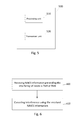
- FIG. 3 illustrates a flow diagram of a method, according to an embodiment
- FIG. 4 illustrates a block diagram of an apparatus, according to another embodiment
- FIG. 5 illustrates a block diagram of an apparatus, according to another embodiment.
- FIG. 6 illustrates a flow diagram of a method, according to another embodiment.
- Interference handling in Rel-12 includes CoMP, enhanced CoMP (eCoMP), inter-cell interference coordination (ICIC), evolved ICIC (eICIC), and NAICS.
- CoMP enhanced CoMP
- ICIC inter-cell interference coordination
- eICIC evolved ICIC
- NAICS NAICS
- CoMP dynamic point muting
- JT joint transmission
- DPS dynamic point selection
- embodiments can provide many variations for the joint NAICS and CoMP operation. Some exemplary scenarios are discussed below, with some simplified assumptions for illustrative purposes.
- a Rel-12 network may be comprised of eNBs supporting the NAICS signaling.
- UEs are NAICS capable UEs (Rel-12 NAICS) and CoMP capable (e.g., TM10 with multiple CSI processes).
- DPM dynamic point muting
- all the UEs are assumed to be configured with TM 10.
- multiple channel state information (CSI) processes are configured, each with a different interference measurement resource (IMR) corresponding to different interference/muting hypothesis.
- IMR interference measurement resource
- CSI-RS channel state information reference signal
- CSI-RS channel state information reference signal
- the difference between a TM9 and TM10 is the multiple CSI processes for feedback.
- the physical downlink shared channel (PDSCH) demodulation may be the same. With the above operation, CoMP DPM gains can be achieved.
- NAICS may be operated based on TM10 UEs even if TM10 as such is not part of the interference cancelation.
- TM10 may operate in single cell ID scenarios where multiple points share the same physical cell ID. This means that the TM10 relies in that scenario on quasi-collocation (QCL) and virtual cell Id (vSCID) signaling.
- QCL quasi-collocation
- vSCID virtual cell Id
- TM10 is also possible to be operated in non-single cell ID cases and hence the QCL and vSCID are not needed.
- the network can configure NAICS signaling pretending interference cells operating in TM9 which is facilitated by the TM subset information in the NAICS signaling.
- a network node e.g., eNB
- a prerequisite for this operation is that the NAICS UE is operating in TM10. With this, NAICS can be achieved.
- FIG. 1 illustrates one example of CoMP and NAICS operation, according to an embodiment.
- three access nodes are depicted as eNB A 100 , eNB B 110 , and eNB C 120 .
- the example of FIG. 1 illustrates two mobile devices as UE1 130 and UE2 135 . It should be noted that embodiments of the invention are not limited to this configuration or number of nodes, and any number of access nodes and mobile devices may be incorporated.
- the DPM serving point is eNB A, while the two points involved in DPM are eNB A and eNB B.
- the dominant interference that the victim UE1 is experiencing is coming from eNB B and/or eNB C. More specifically, the interference that UE1 experiences may be a result of the transmission from eNB B and/or eNB C toward UE2.
- eNB B may be considered to be the dominant interferer. When eNB B is muted, the first dominant interferer may become eNB C.
- the network may enable dynamic point muting in a network operating on TM10 using NAICS signaling designed for TM9 or TM8.
- the network may then configure NAICS signaling to NAICS UE pretending interference UE modes as TM9 or TM8, although the interfering UE is configured in TM10 with multiple CSI processes.
- standard related support may include: 1. test case definitions in RAN4, specifically NAICS TM10 UE with interference cancellation capability for TMs 1, 2, 3, 4, 6, 8 and/or 9; 2. radio resource control (RRC) signaling design for NAICS should be irrelevant to the receive or victim UE's transmission mode (e.g., TM 10 UE can recognize NAICS signaling).
- RRC radio resource control
- the network configures the victim UE and the interference UE in TM10 with multiple CSI processes to perform dynamic muting. All CSI processes of one UE may share a common CSI-RS resource.
- the network may then signal NAICS information to victim NAICS UE pretending interfering UE is in a demodulation reference signal (DMRS) based mode, such as TM9 or TM8.
- DMRS demodulation reference signal
- the TM10 UE may cancel the interference from TM9 or TM 8 UE.
- the network node e.g., eNB
- transmits e.g., on PDSCH
- Table 1 shows an example of the results of one simulation study. From these simulation results, the benefits of joint NAICS and CoMP operation can clearly be seen. In particular, the cell edge gain and sector throughput (TH) gain both increase with the joint operation.
- TH sector throughput
- the results in Table 1 involve a coordination area of 9 cells.
- the area there are a number of active UEs that are reporting CSI per muting hypothesis.
- each UE could report CQI under i) the hypothesis with no cell muted, ii) hypothesis with the dominant cell muted, iii) hypothesis with second dominant cell muted.
- the scheduler evaluates all possible hypothesis and picks the one that maximizes some metric. Supposing one of 9 cells is muted, there are still 8 UEs that are scheduled in the non-muted cells. Since each UE has a different dominant interferer, there is no reason that the cell that was muted is the dominant interferer for all scheduled UEs.
- DPM even with DPM, there is a significant number of UEs that have active dominant interferers and that could still benefit from applying NAICS receivers.
- joint NAICS and DPM provide gains over just NAICS or DPM.
- NAICS receivers from Rel-12 include symbol level interference canceller (SLIC) and reduced complexity maximum likelihood (R-ML), or enhanced interference rejection combining (IRC), there can be issues if the resource elements (REs) assumed to be taken by interfering PDSCH transmissions are actually for interference measurement resources (IMRs).
- REs resource elements
- IMRs interference measurement resources
- the performance degradation is small.
- the IMRs from an adjacent cell can be covered by the zero power CSI-RS in the serving cell, so the problem can be minimized or avoided, at a small cost of not transmitting on a few REs at sparse occasions.
- Rel-12 NACIS doesn't support TM10
- some embodiments utilize implementation based approach to support NAICS together with DPM. As a result, the performance gain of NAICS and CoMP can be combined.
- FIG. 2 illustrates an example of an apparatus 10 according to an embodiment.
- apparatus 10 may be a node, host, or server in a communications network or serving such a network, such as a base station in a communications network or eNB in LTE. It should be noted that one of ordinary skill in the art would understand that apparatus 10 may include components or features not shown in FIG. 2 .
- apparatus 10 may include a processor 22 for processing information and executing instructions or operations.
- processor 22 may be any type of general or specific purpose processor. While a single processor 22 is shown in FIG. 2 , multiple processors may be utilized according to other embodiments. In fact, processor 22 may include one or more of general-purpose computers, special purpose computers, microprocessors, digital signal processors (DSPs), field-programmable gate arrays (FPGAs), application-specific integrated circuits (ASICs), and processors based on a multi-core processor architecture, as examples.
- DSPs digital signal processors
- FPGAs field-programmable gate arrays
- ASICs application-specific integrated circuits
- Apparatus 10 may further include or be coupled to a memory 14 (internal or external), which may be coupled to processor 22 , for storing information and instructions that may be executed by processor 22 .
- Memory 14 may be one or more memories and of any type suitable to the local application environment, and may be implemented using any suitable volatile or nonvolatile data storage technology such as a semiconductor-based memory device, a magnetic memory device and system, an optical memory device and system, fixed memory, and removable memory.
- memory 14 can be comprised of any combination of random access memory (RAM), read only memory (ROM), static storage such as a magnetic or optical disk, or any other type of non-transitory machine or computer readable media.
- the instructions stored in memory 14 may include program instructions or computer program code that, when executed by processor 22 , enable the apparatus 10 to perform tasks as described herein.
- Apparatus 10 may also include or be coupled to one or more antennas 25 for transmitting and receiving signals and/or data to and from apparatus 10 .
- Apparatus 10 may further include or be coupled to a transceiver 28 configured to transmit and receive information.
- transceiver 28 may be configured to modulate information on to a carrier waveform for transmission by the antenna(s) 25 and demodulate information received via the antenna(s) 25 for further processing by other elements of apparatus 10 .
- transceiver 28 may be capable of transmitting and receiving signals or data directly.
- Processor 22 may perform functions associated with the operation of apparatus 10 which may include, for example, precoding of antenna gain/phase parameters, encoding and decoding of individual bits forming a communication message, formatting of information, and overall control of the apparatus 10 , including processes related to management of communication resources.
- memory 14 may store software modules that provide functionality when executed by processor 22 .
- the modules may include, for example, an operating system that provides operating system functionality for apparatus 10 .
- the memory may also store one or more functional modules, such as an application or program, to provide additional functionality for apparatus 10 .
- the components of apparatus 10 may be implemented in hardware, or as any suitable combination of hardware and software.
- apparatus 10 may be an access node, such as a base station or eNB.
- apparatus 10 may be controlled by memory 14 and processor 22 to configure a victim UE (i.e., a UE experiencing interference) and interfering UE in transmission mode 10 (TM10) with multiple channel state information (CSI) processes to perform dynamic point muting (DPM).
- apparatus 10 may be further controlled by memory 14 and processor 22 to signal network assisted interference cancellation and suppression (NAICS) information to the victim UE pretending the mode of the interfering UE is transmission mode 9 (TM9) or transmission mode 8 (TM8).
- NAICS network assisted interference cancellation and suppression
- apparatus 10 may be controlled by memory 14 and processor 22 to transmit physical downlink shared channel (PDSCH) to the interfering user equipment from a same serving point.
- PDSCH physical downlink shared channel
- the signaling of the NAICS information causes the victim user equipment to cancel interference from the interfering user equipment.
- all channel state information (CSI) processes of one user equipment share a common channel state information reference signal (CSI-RS) resource.
- CSI-RS channel state information reference signal
- apparatus 10 may be a mobile device or user equipment (UE) or a modem, for example.
- apparatus 10 may be configured, by a network node (e.g. eNB), to perform dynamic point muting.
- Apparatus 10 may be controlled by memory 14 and processor 22 to receive, from the network, network assisted interference cancellation and suppression (NAICS) information pretending a transmission mode of the interfering user equipment is transmission mode 9 or transmission mode 8.
- NAICS network assisted interference cancellation and suppression
- apparatus 10 may be controlled by memory 14 and processor 22 to cancel interference from the interfering user equipment using the received NAICS information.
- NAICS network assisted interference cancellation and suppression
- FIG. 3 illustrates an example flow diagram of a method, according to one embodiment.
- the method illustrated in FIG. 3 may be performed by a network node, such as an eNB.
- the method may include, at 300 , configuring a victim UE (e.g., interfered UE) and interfering UE in transmission mode 10 (TM10) with multiple channel state information (CSI) processes to perform dynamic point muting (DPM).
- the method may also include, at 310 , causing signaling NAICS information to the victim UE pretending the interfering user equipment mode (the transmission mode of the interfering user equipment) is transmission mode 9 (TM9) or transmission mode 8 (TM8).
- TM9 transmission mode 9
- TM8 transmission mode 8
- the method may further include transmitting on PDSCH to the interfering UE from a same serving point.
- the signaling of the NAICS information causes the victim UE to cancel interference from the interfering UE.
- FIG. 4 illustrates a block diagram of an apparatus 400 , according to another embodiment.
- apparatus 400 may include a configuring unit (or means) 410 for configuring a victim UE and interfering UE in TM10 with multiple CSI processes to perform DPM.
- Apparatus 400 may further include a signaling unit (or means) 420 for signaling NAICS information to the victim UE pretending the interfering UE is in TM9 or TM8. This causes the victim UE to be able to cancel the interference from the interfering UE.
- FIG. 5 illustrates an example of an apparatus 500 , according to another embodiment.
- apparatus 500 may be a mobile device or user equipment (UE) or a modem, for example.
- Apparatus 500 may be configured, by a network node (e.g. eNB), to perform dynamic point muting.
- apparatus 500 may include a processing unit (or means) 510 and transceiver unit (or means) 520 .
- transceiver unit 520 may be configured to receive, from the network, network assisted interference cancellation and suppression (NAICS) information pretending an interfering user equipment mode is transmission mode 9 or transmission mode 8.
- processing unit 510 may be configured to cause apparatus 500 to cancel interference from the interfering user equipment using the received NAICS information.
- NAICS network assisted interference cancellation and suppression
- FIG. 6 illustrates an example flow diagram of a method, according to another embodiment.
- the method illustrated in FIG. 6 may be performed by a mobile device, such as UE, or may be performed by a processor or controller of the UE.
- the method may include, at 600 , receiving, from a network (e.g., eNB), network assisted interference cancellation and suppression (NAICS) information pretending an interfering user equipment mode (the transmission mode of the interfering user equipment) is transmission mode 9 or transmission mode 8.
- the method may further include, at 610 , canceling interference from the interfering user equipment using the received NAICS information.
- a network e.g., eNB
- NAICS network assisted interference cancellation and suppression
- any of the methods described herein may be implemented by software and/or computer program code stored in memory or other computer readable or tangible media, and executed by a processor.
- the functionality may be performed by hardware, for example through the use of an application specific integrated circuit (ASIC), a programmable gate array (PGA), a field programmable gate array (FPGA), or any other combination of hardware and software.
- ASIC application specific integrated circuit
- PGA programmable gate array
- FPGA field programmable gate array
Landscapes
- Engineering & Computer Science (AREA)
- Computer Networks & Wireless Communication (AREA)
- Signal Processing (AREA)
- Mobile Radio Communication Systems (AREA)
Abstract
Description
| TABLE 1 | |||
| Avg TH | Cell edge TH | Utilization | |
| Setup | (Mbps) | (Kbps) | Ratio |
| IRC | 17.34 | 3617.19 | 0.387 |
| NAICS | 18.25 (5.3%) | 3895.79 (7.7%) | 0.37 |
| IRC, CoMP | 19.03 (9.7%) | 3975.81 (9.9%) | 0.318 |
| dynamic muting | |||
| NAICS, CoMP | 20.06 (15.7%) | 4298.49 (18.8%) | 0.305 |
| dynamic muting | |||
Claims (15)
Priority Applications (2)
| Application Number | Priority Date | Filing Date | Title |
|---|---|---|---|
| US14/541,788 US9544085B2 (en) | 2014-11-14 | 2014-11-14 | Method and apparatus for interference cancellation |
| PCT/EP2015/074468 WO2016074897A1 (en) | 2014-11-14 | 2015-10-22 | A method and apparatus for interference cancellation |
Applications Claiming Priority (1)
| Application Number | Priority Date | Filing Date | Title |
|---|---|---|---|
| US14/541,788 US9544085B2 (en) | 2014-11-14 | 2014-11-14 | Method and apparatus for interference cancellation |
Publications (2)
| Publication Number | Publication Date |
|---|---|
| US20160142169A1 US20160142169A1 (en) | 2016-05-19 |
| US9544085B2 true US9544085B2 (en) | 2017-01-10 |
Family
ID=54361067
Family Applications (1)
| Application Number | Title | Priority Date | Filing Date |
|---|---|---|---|
| US14/541,788 Active 2035-02-07 US9544085B2 (en) | 2014-11-14 | 2014-11-14 | Method and apparatus for interference cancellation |
Country Status (2)
| Country | Link |
|---|---|
| US (1) | US9544085B2 (en) |
| WO (1) | WO2016074897A1 (en) |
Families Citing this family (3)
| Publication number | Priority date | Publication date | Assignee | Title |
|---|---|---|---|---|
| US10505697B2 (en) | 2016-11-03 | 2019-12-10 | At&T Intellectual Property I, L.P. | Facilitating a mobile device specific physical downlink shared channel resource element mapping indicator |
| US10091777B1 (en) | 2017-03-31 | 2018-10-02 | At&T Intellectual Property I, L.P. | Facilitating physical downlink shared channel resource element mapping indicator |
| CN109729537B (en) * | 2017-10-31 | 2021-11-19 | 中国移动通信有限公司研究院 | Transmission mode determining method and network side equipment |
Citations (3)
| Publication number | Priority date | Publication date | Assignee | Title |
|---|---|---|---|---|
| WO2014133650A1 (en) | 2013-03-01 | 2014-09-04 | Intel IP Corporation | Quasi co-location and pdsch resource element mapping signaling for network assisted interference mitigation |
| WO2014160984A1 (en) | 2013-03-29 | 2014-10-02 | Intel IP Corporation | Network assisted interference cancellation and suppression with respect to interfering control channel transmissions |
| US20150270917A1 (en) * | 2014-03-21 | 2015-09-24 | Nvidia Corporation | Estimating channel information |
-
2014
- 2014-11-14 US US14/541,788 patent/US9544085B2/en active Active
-
2015
- 2015-10-22 WO PCT/EP2015/074468 patent/WO2016074897A1/en not_active Ceased
Patent Citations (3)
| Publication number | Priority date | Publication date | Assignee | Title |
|---|---|---|---|---|
| WO2014133650A1 (en) | 2013-03-01 | 2014-09-04 | Intel IP Corporation | Quasi co-location and pdsch resource element mapping signaling for network assisted interference mitigation |
| WO2014160984A1 (en) | 2013-03-29 | 2014-10-02 | Intel IP Corporation | Network assisted interference cancellation and suppression with respect to interfering control channel transmissions |
| US20150270917A1 (en) * | 2014-03-21 | 2015-09-24 | Nvidia Corporation | Estimating channel information |
Non-Patent Citations (8)
| Title |
|---|
| 3GPP TSG RAN WG1 #78 Dresden, Germany, Aug. 18-22, 2014 R1-143516. |
| 3GPP TSG RAN WG1 Meeting #78 R1-142801 Dresden, Germany, Aug. 18-22, 2014; Final Report of 3GPP TSG RAN WG1 #77 v1.0.0; MCC Support. |
| 3GPP TSG RAN WG1 Meeting #78 R1-143299 Dresden, Germany, Aug. 18-22, 2014; Higher Layer Signaling of TM10 DMRS Properties for NAICS; Ericsson. |
| 3GPP TSG RAN WG1 Meeting #78bis R1-144335 Ljubljana, Slovenia, Oct. 6-10, 2014; Final Report of 3GPP TSG RAN WG1 #78 v1.1.0; MCC Support. |
| Intel, R4-143034, "Discussion on NAICS interference semi-static parameters blind detection and signaling", 3GPP TSG-RAN WG4 Meeting #71, Seoul, Korea May 19-23, 2014. * |
| International Search Report application No. PCT/EP2015/074468 mailed Dec. 23, 2015. |
| R4-142000; NVIDIA; "Discussion on higher-layer signaling for NAICS"; 3GPP TSG-RAN WG4 Meeting #70bis; San Jose Del Cabo, Mexico, Mar. 31-Apr. 4, 2014. |
| R4-143034; Intel Corporation; "Discussion on NAICS interterence semi-static parameters blind detection and signaling"; 3GPP TSG-RAN WG4 Meeting #71; Seoul, Korea, May 19-23, 2014. |
Also Published As
| Publication number | Publication date |
|---|---|
| US20160142169A1 (en) | 2016-05-19 |
| WO2016074897A1 (en) | 2016-05-19 |
Similar Documents
| Publication | Publication Date | Title |
|---|---|---|
| US12063175B2 (en) | Systems and methods for adaptation in a wireless network | |
| US10530555B2 (en) | Apparatus and method for cancelling inter-cell interference in communication system | |
| US9755800B2 (en) | Method and device for canceling interference and receiving data in wireless communication system | |
| US10057031B2 (en) | Method and apparatus for estimating channel in wireless communication system | |
| US10148299B2 (en) | Method and apparatus for cancelling interference and receiving signal in wireless communication system | |
| US9729292B2 (en) | Method and apparatus for receiving data in wireless communication system supporting cooperative transmission | |
| US20190109679A1 (en) | System and Method for Control Signaling | |
| US9698951B2 (en) | Method and apparatus for transmitting/receiving channel state information in wireless communication system | |
| US9986545B2 (en) | Method for applying Physical Resource Block (PRB) bundling in wireless communications system and apparatus therefor | |
| US10651988B2 (en) | Method and device for selecting multiple users and allocating resources for non-orthogonal multiple access in wireless communication system | |
| WO2019029400A1 (en) | System and method for beam failure recovery | |
| US9935753B2 (en) | Method and device for receiving signal by removing interference in wireless communication system | |
| US9590705B2 (en) | Method and device for transmitting and receiving channel state information in wireless communication system | |
| US10470075B2 (en) | Method and apparatus for removing interference and receiving signal in wireless communication system | |
| US9986540B2 (en) | Method and device for removing interference from wireless communication system and receiving data | |
| US9887818B2 (en) | Method and apparatus for transreceiving channel state information in wireless communication system | |
| US10057002B2 (en) | Method and apparatus for removing interference and receiving signal in wireless communication system | |
| US9544085B2 (en) | Method and apparatus for interference cancellation | |
| US10630368B2 (en) | Method and device for supporting multi-user multi-stream in wireless communication system |
Legal Events
| Date | Code | Title | Description |
|---|---|---|---|
| AS | Assignment |
Owner name: NOKIA SOLUTIONS AND NETWORKS OY, FINLAND Free format text: ASSIGNMENT OF ASSIGNORS INTEREST;ASSIGNORS:YANG, WEIDONG;WANG, XIAOYI;ENESCU, MIHAI;AND OTHERS;SIGNING DATES FROM 20141201 TO 20150114;REEL/FRAME:035151/0347 |
|
| FEPP | Fee payment procedure |
Free format text: PAYOR NUMBER ASSIGNED (ORIGINAL EVENT CODE: ASPN); ENTITY STATUS OF PATENT OWNER: LARGE ENTITY |
|
| STCF | Information on status: patent grant |
Free format text: PATENTED CASE |
|
| AS | Assignment |
Owner name: WSOU INVESTMENTS, LLC, CALIFORNIA Free format text: ASSIGNMENT OF ASSIGNORS INTEREST;ASSIGNOR:NOKIA SOLUTIONS AND NETWORKS OY;REEL/FRAME:044658/0666 Effective date: 20171222 |
|
| MAFP | Maintenance fee payment |
Free format text: PAYMENT OF MAINTENANCE FEE, 4TH YEAR, LARGE ENTITY (ORIGINAL EVENT CODE: M1551); ENTITY STATUS OF PATENT OWNER: LARGE ENTITY Year of fee payment: 4 |
|
| AS | Assignment |
Owner name: OT WSOU TERRIER HOLDINGS, LLC, CALIFORNIA Free format text: SECURITY INTEREST;ASSIGNOR:WSOU INVESTMENTS, LLC;REEL/FRAME:056990/0081 Effective date: 20210528 |
|
| FEPP | Fee payment procedure |
Free format text: MAINTENANCE FEE REMINDER MAILED (ORIGINAL EVENT CODE: REM.); ENTITY STATUS OF PATENT OWNER: LARGE ENTITY |
|
| FEPP | Fee payment procedure |
Free format text: 7.5 YR SURCHARGE - LATE PMT W/IN 6 MO, LARGE ENTITY (ORIGINAL EVENT CODE: M1555); ENTITY STATUS OF PATENT OWNER: LARGE ENTITY |
|
| MAFP | Maintenance fee payment |
Free format text: PAYMENT OF MAINTENANCE FEE, 8TH YEAR, LARGE ENTITY (ORIGINAL EVENT CODE: M1552); ENTITY STATUS OF PATENT OWNER: LARGE ENTITY Year of fee payment: 8 |