US9543527B2 - Red phosphorescent compound and organic light emitting diode device using the same - Google Patents
Red phosphorescent compound and organic light emitting diode device using the same Download PDFInfo
- Publication number
- US9543527B2 US9543527B2 US14/087,277 US201314087277A US9543527B2 US 9543527 B2 US9543527 B2 US 9543527B2 US 201314087277 A US201314087277 A US 201314087277A US 9543527 B2 US9543527 B2 US 9543527B2
- Authority
- US
- United States
- Prior art keywords
- substituted
- carbazole
- compound
- mol
- red phosphorescent
- Prior art date
- Legal status (The legal status is an assumption and is not a legal conclusion. Google has not performed a legal analysis and makes no representation as to the accuracy of the status listed.)
- Active, expires
Links
- VJGQGCYIKWYYNC-UHFFFAOYSA-N CC1=CC2=C(C3=C1C=CC=C3)N([Ar])C1=C2C=C([Ar])C=C1.[Ar] Chemical compound CC1=CC2=C(C3=C1C=CC=C3)N([Ar])C1=C2C=C([Ar])C=C1.[Ar] VJGQGCYIKWYYNC-UHFFFAOYSA-N 0.000 description 4
- MHAAFNTWIDCCHN-UHFFFAOYSA-N [Ar].[Ar]C1=CC2=C(C=C1)N([Ar])C1=C2C2=C(C=CC=C2)C=C1 Chemical compound [Ar].[Ar]C1=CC2=C(C=C1)N([Ar])C1=C2C2=C(C=CC=C2)C=C1 MHAAFNTWIDCCHN-UHFFFAOYSA-N 0.000 description 4
- 0 *c(cc1)cc(c2c(cccc3)c3ccc22)c1[n]2[Al] Chemical compound *c(cc1)cc(c2c(cccc3)c3ccc22)c1[n]2[Al] 0.000 description 3
- WPKLIOMPDMQRGY-UHFFFAOYSA-N C1=CC(C2=C3C=CC=NC3=C3N=CC=CC3=C2)=CN=C1.C1=CC(C2=CC=CC3=CN=CC=C32)=CN=C1.C1=CC(C2=NC3=C(C=CC=C3)C=C2)=CN=C1.C1=CC2=C(N=C1)C1=C(C=CC=N1)C=C2.C1=CC2=CC=NC(C3=CN=CC=C3)=C2C=C1.C1=CC2=CC=NC=C2C(C2=CN=CC=C2)=C1.C1=CC2=CC=NC=C2C=C1.C1=CC=C(C2=CC(C3=NC=CC=C3)=CC=N2)N=C1.C1=CC=C(C2=NC=CC=C2)N=C1.C1=CC=NC=C1.C1=CN=C(C2=C3C=CC=CC3=CC=N2)C=C1.C1=CN=C(C2=C3C=CC=NC3=C3N=CC=CC3=C2)C=C1.C1=CN=C(C2=CC3=CC=NC=C3C=C2)C=C1.C1=CN=C(C2=CC3=CN=CC=C3C=C2)C=C1.C1=CN=C(C2=NC3=C(C=CC=C3)C=C2)C=C1.C1=CN=C2C=CC=CC2=C1.C1=CN=CC(C2=CN=CC=C2)=C1.CC.CC.CC.CC.CC.CC.CC.CC.CC.CC.CC.CC.CC.CC.CC.CC.CC Chemical compound C1=CC(C2=C3C=CC=NC3=C3N=CC=CC3=C2)=CN=C1.C1=CC(C2=CC=CC3=CN=CC=C32)=CN=C1.C1=CC(C2=NC3=C(C=CC=C3)C=C2)=CN=C1.C1=CC2=C(N=C1)C1=C(C=CC=N1)C=C2.C1=CC2=CC=NC(C3=CN=CC=C3)=C2C=C1.C1=CC2=CC=NC=C2C(C2=CN=CC=C2)=C1.C1=CC2=CC=NC=C2C=C1.C1=CC=C(C2=CC(C3=NC=CC=C3)=CC=N2)N=C1.C1=CC=C(C2=NC=CC=C2)N=C1.C1=CC=NC=C1.C1=CN=C(C2=C3C=CC=CC3=CC=N2)C=C1.C1=CN=C(C2=C3C=CC=NC3=C3N=CC=CC3=C2)C=C1.C1=CN=C(C2=CC3=CC=NC=C3C=C2)C=C1.C1=CN=C(C2=CC3=CN=CC=C3C=C2)C=C1.C1=CN=C(C2=NC3=C(C=CC=C3)C=C2)C=C1.C1=CN=C2C=CC=CC2=C1.C1=CN=CC(C2=CN=CC=C2)=C1.CC.CC.CC.CC.CC.CC.CC.CC.CC.CC.CC.CC.CC.CC.CC.CC.CC WPKLIOMPDMQRGY-UHFFFAOYSA-N 0.000 description 2
- MBKYQJCXIAKBFD-UHFFFAOYSA-N C1=CC(C2=CC=C(C3=CC4=C(C=C3)N(C3=CC=C5C=CC=CC5=N3)C3=C4C4=C(C=CC=C4)C=C3)N=C2)=CN=C1.C1=CC2=CC=C(C3=CC4=C(C=C3)N(C3=CC=C5C=CC=CC5=N3)C3=C4C4=C(C=CC=C4)C=C3)N=C2C=C1.C1=CC2=CC=C(N3C4=C(C=C(C5=C6C=CC=CC6=CC=N5)C=C4)C4=C3C=CC3=C4C=CC=C3)N=C2C=C1.C1=CN=CC(C2=CC3=C(C=C2)N(C2=CC=C4C=CC=CC4=N2)C2=C3C3=C(C=CC=C3)C=C2)=C1 Chemical compound C1=CC(C2=CC=C(C3=CC4=C(C=C3)N(C3=CC=C5C=CC=CC5=N3)C3=C4C4=C(C=CC=C4)C=C3)N=C2)=CN=C1.C1=CC2=CC=C(C3=CC4=C(C=C3)N(C3=CC=C5C=CC=CC5=N3)C3=C4C4=C(C=CC=C4)C=C3)N=C2C=C1.C1=CC2=CC=C(N3C4=C(C=C(C5=C6C=CC=CC6=CC=N5)C=C4)C4=C3C=CC3=C4C=CC=C3)N=C2C=C1.C1=CN=CC(C2=CC3=C(C=C2)N(C2=CC=C4C=CC=CC4=N2)C2=C3C3=C(C=CC=C3)C=C2)=C1 MBKYQJCXIAKBFD-UHFFFAOYSA-N 0.000 description 2
- FCAFKUSMOMOYDL-UHFFFAOYSA-N C1=CC(C2=CC=C(C3=CC4=C(C=C3)N(C3=NC=C(C5=C6C=CC=NC6=C6N=CC=CC6=C5)C=C3)C3=C4C4=C(C=CC=C4)C=C3)N=C2)=CN=C1.C1=CC2=CC=C(C3=CC4=C(C=C3)N(C3=NC=C(C5=C6C=CC=NC6=C6N=CC=CC6=C5)C=C3)C3=C4C4=C(C=CC=C4)C=C3)N=C2C=C1.C1=CC2=CC=NC(C3=CC4=C(C=C3)N(C3=NC=C(C5=C6C=CC=NC6=C6N=CC=CC6=C5)C=C3)C3=C4C4=C(C=CC=C4)C=C3)=C2C=C1 Chemical compound C1=CC(C2=CC=C(C3=CC4=C(C=C3)N(C3=NC=C(C5=C6C=CC=NC6=C6N=CC=CC6=C5)C=C3)C3=C4C4=C(C=CC=C4)C=C3)N=C2)=CN=C1.C1=CC2=CC=C(C3=CC4=C(C=C3)N(C3=NC=C(C5=C6C=CC=NC6=C6N=CC=CC6=C5)C=C3)C3=C4C4=C(C=CC=C4)C=C3)N=C2C=C1.C1=CC2=CC=NC(C3=CC4=C(C=C3)N(C3=NC=C(C5=C6C=CC=NC6=C6N=CC=CC6=C5)C=C3)C3=C4C4=C(C=CC=C4)C=C3)=C2C=C1 FCAFKUSMOMOYDL-UHFFFAOYSA-N 0.000 description 2
- NOBZXIXDHXIABB-UHFFFAOYSA-N C1=CC(C2=CC=C(C3=CC4=C(C=C3)N(C3=NC=CC5=C3C=CC=C5)C3=C4C4=C(C=CC=C4)C=C3)N=C2)=CN=C1.C1=CC2=CC=C(C3=CC4=C(C=C3)N(C3=NC=CC5=C3C=CC=C5)C3=C4C4=C(C=CC=C4)C=C3)N=C2C=C1.C1=CC2=CC=NC(C3=CC4=C(C=C3)N(C3=NC=CC5=C3C=CC=C5)C3=C4C4=C(C=CC=C4)C=C3)=C2C=C1.C1=CN=C(C2=CC=C(C3=CC4=C(C=C3)N(C3=NC=CC5=C3C=CC=C5)C3=C4C4=C(C=CC=C4)C=C3)C=N2)C=C1 Chemical compound C1=CC(C2=CC=C(C3=CC4=C(C=C3)N(C3=NC=CC5=C3C=CC=C5)C3=C4C4=C(C=CC=C4)C=C3)N=C2)=CN=C1.C1=CC2=CC=C(C3=CC4=C(C=C3)N(C3=NC=CC5=C3C=CC=C5)C3=C4C4=C(C=CC=C4)C=C3)N=C2C=C1.C1=CC2=CC=NC(C3=CC4=C(C=C3)N(C3=NC=CC5=C3C=CC=C5)C3=C4C4=C(C=CC=C4)C=C3)=C2C=C1.C1=CN=C(C2=CC=C(C3=CC4=C(C=C3)N(C3=NC=CC5=C3C=CC=C5)C3=C4C4=C(C=CC=C4)C=C3)C=N2)C=C1 NOBZXIXDHXIABB-UHFFFAOYSA-N 0.000 description 2
- DJRCLFBTGGKBII-UHFFFAOYSA-N C1=CC2=C(C=C1)C(N1C3=C(C=C(C4=CC=C(C5=CC6=C(N=CC=C6)C6=C5C=CC=N6)C=N4)C=C3)C3=C1C=CC1=C3C=CC=C1)=NC=C2.C1=CC2=CC=C(C3=CC=C(C4=CC5=C(C=C4)N(C4=NC=CC6=C4C=CC=C6)C4=C5C5=C(C=CC=C5)C=C4)N=C3)N=C2C=C1.C1=CC2=CC=NC(C3=CC=C(C4=CC5=C(C=C4)N(C4=NC=CC6=C4C=CC=C6)C4=C5C5=C(C=CC=C5)C=C4)N=C3)=C2C=C1.C1=CC=C(C2=CC3=C(C=C2)N(C2=CC=C4C=CC=CC4=N2)C2=C3C3=C(C=CC=C3)C=C2)N=C1 Chemical compound C1=CC2=C(C=C1)C(N1C3=C(C=C(C4=CC=C(C5=CC6=C(N=CC=C6)C6=C5C=CC=N6)C=N4)C=C3)C3=C1C=CC1=C3C=CC=C1)=NC=C2.C1=CC2=CC=C(C3=CC=C(C4=CC5=C(C=C4)N(C4=NC=CC6=C4C=CC=C6)C4=C5C5=C(C=CC=C5)C=C4)N=C3)N=C2C=C1.C1=CC2=CC=NC(C3=CC=C(C4=CC5=C(C=C4)N(C4=NC=CC6=C4C=CC=C6)C4=C5C5=C(C=CC=C5)C=C4)N=C3)=C2C=C1.C1=CC=C(C2=CC3=C(C=C2)N(C2=CC=C4C=CC=CC4=N2)C2=C3C3=C(C=CC=C3)C=C2)N=C1 DJRCLFBTGGKBII-UHFFFAOYSA-N 0.000 description 2
- YEMOUPSOYJLOKA-UHFFFAOYSA-N C1=CC2=CC(C3=CN=C(C4=CC5=C(C6=C4C=CC=C6)N(C4=CC6=C(N=CC=C6)C6=C4C=CC=N6)C4=C5C=C(C5=CC=C(C6=CC7=C(N=CC=C7)C7=C6C=CC=N7)C=N5)C=C4)C=C3)=C3C=CC=NC3=C2N=C1.C1=CC=C(C2=CC3=C(C=C2)N(C2=NC=C(C4=CC=CN=C4)C=C2)C2=C3C=C(C3=NC=CC=C3)C3=C2C=CC=C3)N=C1.C1=CN=CC(C2=CN=C(N3C4=C(C=C(C5=C6C=CC=CC6=CC=N5)C=C4)C4=C3C3=C(C=CC=C3)C(C3=C5C=CC=CC5=CC=N3)=C4)C=C2)=C1.C1=CN=CC(C2=CN=C(N3C4=C(C=C(C5=CC=CN=C5)C=C4)C4=C3C3=C(C=CC=C3)C(C3=CN=CC=C3)=C4)C=C2)=C1 Chemical compound C1=CC2=CC(C3=CN=C(C4=CC5=C(C6=C4C=CC=C6)N(C4=CC6=C(N=CC=C6)C6=C4C=CC=N6)C4=C5C=C(C5=CC=C(C6=CC7=C(N=CC=C7)C7=C6C=CC=N7)C=N5)C=C4)C=C3)=C3C=CC=NC3=C2N=C1.C1=CC=C(C2=CC3=C(C=C2)N(C2=NC=C(C4=CC=CN=C4)C=C2)C2=C3C=C(C3=NC=CC=C3)C3=C2C=CC=C3)N=C1.C1=CN=CC(C2=CN=C(N3C4=C(C=C(C5=C6C=CC=CC6=CC=N5)C=C4)C4=C3C3=C(C=CC=C3)C(C3=C5C=CC=CC5=CC=N3)=C4)C=C2)=C1.C1=CN=CC(C2=CN=C(N3C4=C(C=C(C5=CC=CN=C5)C=C4)C4=C3C3=C(C=CC=C3)C(C3=CN=CC=C3)=C4)C=C2)=C1 YEMOUPSOYJLOKA-UHFFFAOYSA-N 0.000 description 2
- LROLBWXPXUZSID-UHFFFAOYSA-N C1=CC2=CC(C3=CN=C(C4=CC5=C(C6=C4C=CC=C6)N(C4=NC=C(C6=C7C=CC=NC7=C7N=CC=CC7=C6)C=C4)C4=C5C=C(C5=CC=C(C6=CC7=C(N=CC=C7)C7=C6C=CC=N7)C=N5)C=C4)C=C3)=C3C=CC=NC3=C2N=C1.C1=CC2=CC=C(C3=CC=C(C4=CC5=C(C=C4)N(C4=NC=C(C6=C7C=CC=NC7=C7N=CC=CC7=C6)C=C4)C4=C5C=C(C5=NC=C(C6=NC7=C(C=CC=C7)C=C6)C=C5)C5=C4C=CC=C5)N=C3)N=C2C=C1 Chemical compound C1=CC2=CC(C3=CN=C(C4=CC5=C(C6=C4C=CC=C6)N(C4=NC=C(C6=C7C=CC=NC7=C7N=CC=CC7=C6)C=C4)C4=C5C=C(C5=CC=C(C6=CC7=C(N=CC=C7)C7=C6C=CC=N7)C=N5)C=C4)C=C3)=C3C=CC=NC3=C2N=C1.C1=CC2=CC=C(C3=CC=C(C4=CC5=C(C=C4)N(C4=NC=C(C6=C7C=CC=NC7=C7N=CC=CC7=C6)C=C4)C4=C5C=C(C5=NC=C(C6=NC7=C(C=CC=C7)C=C6)C=C5)C5=C4C=CC=C5)N=C3)N=C2C=C1 LROLBWXPXUZSID-UHFFFAOYSA-N 0.000 description 2
- LUKPVRMXJPXPGY-UHFFFAOYSA-N C1=CC2=CC(C3=CN=C(C4=CC5=C(C6=C4C=CC=C6)N(C4=NC=C(C6=NC=CC7=C6C=CC=C7)C=C4)C4=C5C=C(C5=CC=C(C6=CC7=C(N=CC=C7)C7=C6C=CC=N7)C=N5)C=C4)C=C3)=C3C=CC=NC3=C2N=C1.C1=CC2=CC=C(C3=CC=C(C4=CC5=C(C=C4)N(C4=NC=C(C6=NC=CC7=C6C=CC=C7)C=C4)C4=C5C=C(C5=NC=C(C6=NC7=C(C=CC=C7)C=C6)C=C5)C5=C4C=CC=C5)N=C3)N=C2C=C1.C1=CC=C(C2=CC3=C(C=C2)N(C2=NC=C(C4=CC=C5C=CC=CC5=N4)C=C2)C2=C3C=C(C3=NC=CC=C3)C3=C2C=CC=C3)N=C1 Chemical compound C1=CC2=CC(C3=CN=C(C4=CC5=C(C6=C4C=CC=C6)N(C4=NC=C(C6=NC=CC7=C6C=CC=C7)C=C4)C4=C5C=C(C5=CC=C(C6=CC7=C(N=CC=C7)C7=C6C=CC=N7)C=N5)C=C4)C=C3)=C3C=CC=NC3=C2N=C1.C1=CC2=CC=C(C3=CC=C(C4=CC5=C(C=C4)N(C4=NC=C(C6=NC=CC7=C6C=CC=C7)C=C4)C4=C5C=C(C5=NC=C(C6=NC7=C(C=CC=C7)C=C6)C=C5)C5=C4C=CC=C5)N=C3)N=C2C=C1.C1=CC=C(C2=CC3=C(C=C2)N(C2=NC=C(C4=CC=C5C=CC=CC5=N4)C=C2)C2=C3C=C(C3=NC=CC=C3)C3=C2C=CC=C3)N=C1 LUKPVRMXJPXPGY-UHFFFAOYSA-N 0.000 description 2
- BVHWRJIKLWCRJF-UHFFFAOYSA-N C1=CC2=CC(C3=CN=C(C4=CC5=C(C6=C4C=CC=C6)N(C4=NC=CC6=C4C=CC=C6)C4=C5C=C(C5=CC=C(C6=CC7=C(N=CC=C7)C7=C6C=CC=N7)C=N5)C=C4)C=C3)=C3C=CC=NC3=C2N=C1.C1=CC2=CC=C(C3=CC=C(C4=CC5=C(C=C4)N(C4=NC=CC6=C4C=CC=C6)C4=C5C=C(C5=NC=C(C6=NC7=C(C=CC=C7)C=C6)C=C5)C5=C4C=CC=C5)N=C3)N=C2C=C1.C1=CC2=CC=NC(C3=CC=C(C4=CC5=C(C=C4)N(C4=NC=CC6=C4C=CC=C6)C4=C5C=C(C5=CC=C(C6=C7C=CC=CC7=CC=N6)C=N5)C5=C4C=CC=C5)N=C3)=C2C=C1.C1=CC=C(C2=CC3=C(C=C2)N(C2=CC=C4C=CC=CC4=N2)C2=C3C=C(C3=NC=CC=C3)C3=C2C=CC=C3)N=C1 Chemical compound C1=CC2=CC(C3=CN=C(C4=CC5=C(C6=C4C=CC=C6)N(C4=NC=CC6=C4C=CC=C6)C4=C5C=C(C5=CC=C(C6=CC7=C(N=CC=C7)C7=C6C=CC=N7)C=N5)C=C4)C=C3)=C3C=CC=NC3=C2N=C1.C1=CC2=CC=C(C3=CC=C(C4=CC5=C(C=C4)N(C4=NC=CC6=C4C=CC=C6)C4=C5C=C(C5=NC=C(C6=NC7=C(C=CC=C7)C=C6)C=C5)C5=C4C=CC=C5)N=C3)N=C2C=C1.C1=CC2=CC=NC(C3=CC=C(C4=CC5=C(C=C4)N(C4=NC=CC6=C4C=CC=C6)C4=C5C=C(C5=CC=C(C6=C7C=CC=CC7=CC=N6)C=N5)C5=C4C=CC=C5)N=C3)=C2C=C1.C1=CC=C(C2=CC3=C(C=C2)N(C2=CC=C4C=CC=CC4=N2)C2=C3C=C(C3=NC=CC=C3)C3=C2C=CC=C3)N=C1 BVHWRJIKLWCRJF-UHFFFAOYSA-N 0.000 description 2
- NXCRZMCMGYNTDC-UHFFFAOYSA-N C1=CC2=CC(C3=CN=C(N4C5=C(C=C(C6=CC=C(C7=CC8=C(N=CC=C8)C8=C7C=CC=N8)C=N6)C=C5)C5=C4C=CC4=C5C=CC=C4)C=C3)=C3C=CC=NC3=C2N=C1.C1=CC2=CC=C(C3=CC=C(C4=CC5=C(C=C4)N(C4=NC=C(C6=C7C=CC=NC7=C7N=CC=CC7=C6)C=C4)C4=C5C5=C(C=CC=C5)C=C4)N=C3)N=C2C=C1 Chemical compound C1=CC2=CC(C3=CN=C(N4C5=C(C=C(C6=CC=C(C7=CC8=C(N=CC=C8)C8=C7C=CC=N8)C=N6)C=C5)C5=C4C=CC4=C5C=CC=C4)C=C3)=C3C=CC=NC3=C2N=C1.C1=CC2=CC=C(C3=CC=C(C4=CC5=C(C=C4)N(C4=NC=C(C6=C7C=CC=NC7=C7N=CC=CC7=C6)C=C4)C4=C5C5=C(C=CC=C5)C=C4)N=C3)N=C2C=C1 NXCRZMCMGYNTDC-UHFFFAOYSA-N 0.000 description 2
- RPUUDVVBKATJDC-UHFFFAOYSA-N C1=CC2=CC=C(C3=CC4=C(C=C3)N(C3=CC5=C(N=CC=C5)C5=C3C=CC=N5)C3=C4C=C(C4=NC5=C(C=CC=C5)C=C4)C4=C3C=CC=C4)N=C2C=C1.C1=CC2=CC=NC(C3=CC4=C(C=C3)N(C3=CC5=C(N=CC=C5)C5=C3C=CC=N5)C3=C4C=C(C4=C5C=CC=CC5=CC=N4)C4=C3C=CC=C4)=C2C=C1.C1=CC=C(C2=CC3=C(C=C2)N(C2=CC4=C(N=CC=C4)C4=C2C=CC=N4)C2=C3C=C(C3=NC=CC=C3)C3=C2C=CC=C3)N=C1.C1=CN=CC(C2=CC3=C(C=C2)N(C2=CC4=C(N=CC=C4)C4=C2C=CC=N4)C2=C3C=C(C3=CN=CC=C3)C3=C2C=CC=C3)=C1 Chemical compound C1=CC2=CC=C(C3=CC4=C(C=C3)N(C3=CC5=C(N=CC=C5)C5=C3C=CC=N5)C3=C4C=C(C4=NC5=C(C=CC=C5)C=C4)C4=C3C=CC=C4)N=C2C=C1.C1=CC2=CC=NC(C3=CC4=C(C=C3)N(C3=CC5=C(N=CC=C5)C5=C3C=CC=N5)C3=C4C=C(C4=C5C=CC=CC5=CC=N4)C4=C3C=CC=C4)=C2C=C1.C1=CC=C(C2=CC3=C(C=C2)N(C2=CC4=C(N=CC=C4)C4=C2C=CC=N4)C2=C3C=C(C3=NC=CC=C3)C3=C2C=CC=C3)N=C1.C1=CN=CC(C2=CC3=C(C=C2)N(C2=CC4=C(N=CC=C4)C4=C2C=CC=N4)C2=C3C=C(C3=CN=CC=C3)C3=C2C=CC=C3)=C1 RPUUDVVBKATJDC-UHFFFAOYSA-N 0.000 description 2
- RYZMRKZTWPQDGP-UHFFFAOYSA-N C1=CC2=CC=C(C3=CC4=C(C=C3)N(C3=CC=C5C=CC=CC5=N3)C3=C4C=C(C4=NC5=C(C=CC=C5)C=C4)C4=C3C=CC=C4)N=C2C=C1.C1=CC2=CC=C(N3C4=C(C=C(C5=C6C=CC=CC6=CC=N5)C=C4)C4=C3C3=C(C=CC=C3)C(C3=C5C=CC=CC5=CC=N3)=C4)N=C2C=C1.C1=CN=CC(C2=CC3=C(C=C2)N(C2=CC=C4C=CC=CC4=N2)C2=C3C=C(C3=CN=CC=C3)C3=C2C=CC=C3)=C1.C1=CN=CC(C2=CN=C(C3=CC4=C(C5=C3C=CC=C5)N(C3=CC=C5C=CC=CC5=N3)C3=C4C=C(C4=CC=C(C5=CN=CC=C5)C=N4)C=C3)C=C2)=C1 Chemical compound C1=CC2=CC=C(C3=CC4=C(C=C3)N(C3=CC=C5C=CC=CC5=N3)C3=C4C=C(C4=NC5=C(C=CC=C5)C=C4)C4=C3C=CC=C4)N=C2C=C1.C1=CC2=CC=C(N3C4=C(C=C(C5=C6C=CC=CC6=CC=N5)C=C4)C4=C3C3=C(C=CC=C3)C(C3=C5C=CC=CC5=CC=N3)=C4)N=C2C=C1.C1=CN=CC(C2=CC3=C(C=C2)N(C2=CC=C4C=CC=CC4=N2)C2=C3C=C(C3=CN=CC=C3)C3=C2C=CC=C3)=C1.C1=CN=CC(C2=CN=C(C3=CC4=C(C5=C3C=CC=C5)N(C3=CC=C5C=CC=CC5=N3)C3=C4C=C(C4=CC=C(C5=CN=CC=C5)C=N4)C=C3)C=C2)=C1 RYZMRKZTWPQDGP-UHFFFAOYSA-N 0.000 description 2
- RVYYMIBJWUKDFZ-UHFFFAOYSA-N C1=CC2=CC=C(C3=CC4=C(C=C3)N(C3=CN=CC=C3)C3=C4C=C(C4=NC5=C(C=CC=C5)C=C4)C4=C3C=CC=C4)N=C2C=C1.C1=CC2=CC=NC(C3=CC=C(C4=CC5=C(C=C4)N(C4=CN=CC=C4)C4=C5C=C(C5=CC=C(C6=C7C=CC=CC7=CC=N6)C=N5)C5=C4C=CC=C5)N=C3)=C2C=C1.C1=CC=C(C2=NC=C(C3=CC4=C(C5=C3C=CC=C5)N(C3=CN=CC=C3)C3=C4C=C(C4=CC=C(C5=NC=CC=C5)N=C4)C=C3)C=C2)N=C1.C1=CN=CC(C2=CN=C(C3=CC4=C(C5=C3C=CC=C5)N(C3=CN=CC=C3)C3=C4C=C(C4=CC=C(C5=CN=CC=C5)C=N4)C=C3)C=C2)=C1 Chemical compound C1=CC2=CC=C(C3=CC4=C(C=C3)N(C3=CN=CC=C3)C3=C4C=C(C4=NC5=C(C=CC=C5)C=C4)C4=C3C=CC=C4)N=C2C=C1.C1=CC2=CC=NC(C3=CC=C(C4=CC5=C(C=C4)N(C4=CN=CC=C4)C4=C5C=C(C5=CC=C(C6=C7C=CC=CC7=CC=N6)C=N5)C5=C4C=CC=C5)N=C3)=C2C=C1.C1=CC=C(C2=NC=C(C3=CC4=C(C5=C3C=CC=C5)N(C3=CN=CC=C3)C3=C4C=C(C4=CC=C(C5=NC=CC=C5)N=C4)C=C3)C=C2)N=C1.C1=CN=CC(C2=CN=C(C3=CC4=C(C5=C3C=CC=C5)N(C3=CN=CC=C3)C3=C4C=C(C4=CC=C(C5=CN=CC=C5)C=N4)C=C3)C=C2)=C1 RVYYMIBJWUKDFZ-UHFFFAOYSA-N 0.000 description 2
- FKNFLBJSPDFCSN-UHFFFAOYSA-N C1=CC2=CC=C(C3=CC4=C(C=C3)N(C3=NC=C(C5=C6C=CC=NC6=C6N=CC=CC6=C5)C=C3)C3=C4C=C(C4=NC5=C(C=CC=C5)C=C4)C4=C3C=CC=C4)N=C2C=C1.C1=CC2=CC=NC(C3=CC4=C(C=C3)N(C3=NC=C(C5=C6C=CC=NC6=C6N=CC=CC6=C5)C=C3)C3=C4C=C(C4=C5C=CC=CC5=CC=N4)C4=C3C=CC=C4)=C2C=C1.C1=CN=CC(C2=CC3=C(C=C2)N(C2=NC=C(C4=C5C=CC=NC5=C5N=CC=CC5=C4)C=C2)C2=C3C=C(C3=CN=CC=C3)C3=C2C=CC=C3)=C1 Chemical compound C1=CC2=CC=C(C3=CC4=C(C=C3)N(C3=NC=C(C5=C6C=CC=NC6=C6N=CC=CC6=C5)C=C3)C3=C4C=C(C4=NC5=C(C=CC=C5)C=C4)C4=C3C=CC=C4)N=C2C=C1.C1=CC2=CC=NC(C3=CC4=C(C=C3)N(C3=NC=C(C5=C6C=CC=NC6=C6N=CC=CC6=C5)C=C3)C3=C4C=C(C4=C5C=CC=CC5=CC=N4)C4=C3C=CC=C4)=C2C=C1.C1=CN=CC(C2=CC3=C(C=C2)N(C2=NC=C(C4=C5C=CC=NC5=C5N=CC=CC5=C4)C=C2)C2=C3C=C(C3=CN=CC=C3)C3=C2C=CC=C3)=C1 FKNFLBJSPDFCSN-UHFFFAOYSA-N 0.000 description 2
- JBYPAFILXARCMQ-UHFFFAOYSA-N C1=CC2=CC=C(C3=CC4=C(C=C3)N(C3=NC=C(C5=NC=CC6=C5C=CC=C6)C=C3)C3=C4C=C(C4=NC5=C(C=CC=C5)C=C4)C4=C3C=CC=C4)N=C2C=C1.C1=CC2=CC=NC(C3=CC4=C(C=C3)N(C3=NC=C(C5=NC=CC6=C5C=CC=C6)C=C3)C3=C4C=C(C4=C5C=CC=CC5=CC=N4)C4=C3C=CC=C4)=C2C=C1.C1=CN=CC(C2=CC3=C(C=C2)N(C2=NC=C(C4=NC=CC5=C4C=CC=C5)C=C2)C2=C3C=C(C3=CN=CC=C3)C3=C2C=CC=C3)=C1 Chemical compound C1=CC2=CC=C(C3=CC4=C(C=C3)N(C3=NC=C(C5=NC=CC6=C5C=CC=C6)C=C3)C3=C4C=C(C4=NC5=C(C=CC=C5)C=C4)C4=C3C=CC=C4)N=C2C=C1.C1=CC2=CC=NC(C3=CC4=C(C=C3)N(C3=NC=C(C5=NC=CC6=C5C=CC=C6)C=C3)C3=C4C=C(C4=C5C=CC=CC5=CC=N4)C4=C3C=CC=C4)=C2C=C1.C1=CN=CC(C2=CC3=C(C=C2)N(C2=NC=C(C4=NC=CC5=C4C=CC=C5)C=C2)C2=C3C=C(C3=CN=CC=C3)C3=C2C=CC=C3)=C1 JBYPAFILXARCMQ-UHFFFAOYSA-N 0.000 description 2
- XMEZRBSDFREJAB-UHFFFAOYSA-N C1=CC2=CC=C(C3=CC4=C(C=C3)N(C3=NC=CC5=C3C=CC=C5)C3=C4C=C(C4=NC5=C(C=CC=C5)C=C4)C4=C3C=CC=C4)N=C2C=C1.C1=CC2=CC=NC(C3=CC4=C(C=C3)N(C3=NC=CC5=C3C=CC=C5)C3=C4C=C(C4=C5C=CC=CC5=CC=N4)C4=C3C=CC=C4)=C2C=C1.C1=CC=C(C2=NC=C(C3=CC4=C(C5=C3C=CC=C5)N(C3=NC=CC5=C3C=CC=C5)C3=C4C=C(C4=CC=C(C5=NC=CC=C5)N=C4)C=C3)C=C2)N=C1.C1=CN=CC(C2=CN=C(C3=CC4=C(C5=C3C=CC=C5)N(C3=NC=CC5=C3C=CC=C5)C3=C4C=C(C4=CC=C(C5=CN=CC=C5)C=N4)C=C3)C=C2)=C1 Chemical compound C1=CC2=CC=C(C3=CC4=C(C=C3)N(C3=NC=CC5=C3C=CC=C5)C3=C4C=C(C4=NC5=C(C=CC=C5)C=C4)C4=C3C=CC=C4)N=C2C=C1.C1=CC2=CC=NC(C3=CC4=C(C=C3)N(C3=NC=CC5=C3C=CC=C5)C3=C4C=C(C4=C5C=CC=CC5=CC=N4)C4=C3C=CC=C4)=C2C=C1.C1=CC=C(C2=NC=C(C3=CC4=C(C5=C3C=CC=C5)N(C3=NC=CC5=C3C=CC=C5)C3=C4C=C(C4=CC=C(C5=NC=CC=C5)N=C4)C=C3)C=C2)N=C1.C1=CN=CC(C2=CN=C(C3=CC4=C(C5=C3C=CC=C5)N(C3=NC=CC5=C3C=CC=C5)C3=C4C=C(C4=CC=C(C5=CN=CC=C5)C=N4)C=C3)C=C2)=C1 XMEZRBSDFREJAB-UHFFFAOYSA-N 0.000 description 2
- FPHJFSHVCAJXRR-UHFFFAOYSA-N C1=CC2=CC=C(C3=CC=C(C4=CC5=C(C=C4)N(C4=CC6=C(N=CC=C6)C6=C4C=CC=N6)C4=C5C=C(C5=NC=C(C6=NC7=C(C=CC=C7)C=C6)C=C5)C5=C4C=CC=C5)N=C3)N=C2C=C1.C1=CC2=CC=NC(C3=CC=C(C4=CC5=C(C=C4)N(C4=CC6=C(N=CC=C6)C6=C4C=CC=N6)C4=C5C=C(C5=CC=C(C6=C7C=CC=CC7=CC=N6)C=N5)C5=C4C=CC=C5)N=C3)=C2C=C1.C1=CC=C(C2=NC=C(C3=CC4=C(C5=C3C=CC=C5)N(C3=CC5=C(N=CC=C5)C5=C3C=CC=N5)C3=C4C=C(C4=CC=C(C5=NC=CC=C5)N=C4)C=C3)C=C2)N=C1.C1=CN=CC(C2=CN=C(C3=CC4=C(C5=C3C=CC=C5)N(C3=CC5=C(N=CC=C5)C5=C3C=CC=N5)C3=C4C=C(C4=CC=C(C5=CN=CC=C5)C=N4)C=C3)C=C2)=C1 Chemical compound C1=CC2=CC=C(C3=CC=C(C4=CC5=C(C=C4)N(C4=CC6=C(N=CC=C6)C6=C4C=CC=N6)C4=C5C=C(C5=NC=C(C6=NC7=C(C=CC=C7)C=C6)C=C5)C5=C4C=CC=C5)N=C3)N=C2C=C1.C1=CC2=CC=NC(C3=CC=C(C4=CC5=C(C=C4)N(C4=CC6=C(N=CC=C6)C6=C4C=CC=N6)C4=C5C=C(C5=CC=C(C6=C7C=CC=CC7=CC=N6)C=N5)C5=C4C=CC=C5)N=C3)=C2C=C1.C1=CC=C(C2=NC=C(C3=CC4=C(C5=C3C=CC=C5)N(C3=CC5=C(N=CC=C5)C5=C3C=CC=N5)C3=C4C=C(C4=CC=C(C5=NC=CC=C5)N=C4)C=C3)C=C2)N=C1.C1=CN=CC(C2=CN=C(C3=CC4=C(C5=C3C=CC=C5)N(C3=CC5=C(N=CC=C5)C5=C3C=CC=N5)C3=C4C=C(C4=CC=C(C5=CN=CC=C5)C=N4)C=C3)C=C2)=C1 FPHJFSHVCAJXRR-UHFFFAOYSA-N 0.000 description 2
- NZDRZKHQBLWWRQ-UHFFFAOYSA-N C1=CC2=CC=C(C3=CC=C(C4=CC5=C(C=C4)N(C4=CC=C6C=CC=CC6=N4)C4=C5C5=C(C=CC=C5)C=C4)N=C3)N=C2C=C1.C1=CC2=CC=C(N3C4=C(C=C(C5=CC=C(C6=C7C=CC=CC7=CC=N6)C=N5)C=C4)C4=C3C=CC3=C4C=CC=C3)N=C2C=C1.C1=CN=C(C2=CC=C(C3=CC4=C(C=C3)N(C3=CC=C5C=CC=CC5=N3)C3=C4C4=C(C=CC=C4)C=C3)C=N2)C=C1 Chemical compound C1=CC2=CC=C(C3=CC=C(C4=CC5=C(C=C4)N(C4=CC=C6C=CC=CC6=N4)C4=C5C5=C(C=CC=C5)C=C4)N=C3)N=C2C=C1.C1=CC2=CC=C(N3C4=C(C=C(C5=CC=C(C6=C7C=CC=CC7=CC=N6)C=N5)C=C4)C4=C3C=CC3=C4C=CC=C3)N=C2C=C1.C1=CN=C(C2=CC=C(C3=CC4=C(C=C3)N(C3=CC=C5C=CC=CC5=N3)C3=C4C4=C(C=CC=C4)C=C3)C=N2)C=C1 NZDRZKHQBLWWRQ-UHFFFAOYSA-N 0.000 description 2
- IYZSWOIBBZRDPD-UHFFFAOYSA-N C1=CC2=CC=C(C3=CC=C(C4=CC5=C(C=C4)N(C4=CC=C6C=CC=CC6=N4)C4=C5C=C(C5=NC=C(C6=NC7=C(C=CC=C7)C=C6)C=C5)C5=C4C=CC=C5)N=C3)N=C2C=C1.C1=CC2=CC=C(N3C4=C(C=C(C5=CC=C(C6=C7C=CC=CC7=CC=N6)C=N5)C=C4)C4=C3C3=C(C=CC=C3)C(C3=CC=C(C5=C6C=CC=CC6=CC=N5)C=N3)=C4)N=C2C=C1.C1=CC2=CC=C(N3C4=C(C=C(C5=CC=C(C6=CC7=C(N=CC=C7)C7=C6C=CC=N7)C=N5)C=C4)C4=C3C3=C(C=CC=C3)C(C3=NC=C(C5=C6C=CC=NC6=C6N=CC=CC6=C5)C=C3)=C4)N=C2C=C1.C1=CC=C(C2=NC=C(C3=CC4=C(C5=C3C=CC=C5)N(C3=CC=C5C=CC=CC5=N3)C3=C4C=C(C4=CC=C(C5=NC=CC=C5)N=C4)C=C3)C=C2)N=C1 Chemical compound C1=CC2=CC=C(C3=CC=C(C4=CC5=C(C=C4)N(C4=CC=C6C=CC=CC6=N4)C4=C5C=C(C5=NC=C(C6=NC7=C(C=CC=C7)C=C6)C=C5)C5=C4C=CC=C5)N=C3)N=C2C=C1.C1=CC2=CC=C(N3C4=C(C=C(C5=CC=C(C6=C7C=CC=CC7=CC=N6)C=N5)C=C4)C4=C3C3=C(C=CC=C3)C(C3=CC=C(C5=C6C=CC=CC6=CC=N5)C=N3)=C4)N=C2C=C1.C1=CC2=CC=C(N3C4=C(C=C(C5=CC=C(C6=CC7=C(N=CC=C7)C7=C6C=CC=N7)C=N5)C=C4)C4=C3C3=C(C=CC=C3)C(C3=NC=C(C5=C6C=CC=NC6=C6N=CC=CC6=C5)C=C3)=C4)N=C2C=C1.C1=CC=C(C2=NC=C(C3=CC4=C(C5=C3C=CC=C5)N(C3=CC=C5C=CC=CC5=N3)C3=C4C=C(C4=CC=C(C5=NC=CC=C5)N=C4)C=C3)C=C2)N=C1 IYZSWOIBBZRDPD-UHFFFAOYSA-N 0.000 description 2
- PMQUXJDFGMCBPX-UHFFFAOYSA-N C1=CC2=CC=C(C3=CC=C(C4=CC5=C(C=C4)N(C4=CN=CC=C4)C4=C5C=C(C5=NC=C(C6=NC7=C(C=CC=C7)C=C6)C=C5)C5=C4C=CC=C5)N=C3)N=C2C=C1.C1=CC=C(C2=CC3=C(C=C2)N(C2=NC=CC4=C2C=CC=C4)C2=C3C=C(C3=NC=CC=C3)C3=C2C=CC=C3)N=C1.C1=CN=C(N2C3=C(C=C(C4=CC=C(C5=CC6=C(N=CC=C6)C6=C5C=CC=N6)C=N4)C=C3)C3=C2C2=C(C=CC=C2)C(C2=NC=C(C4=C5C=CC=NC5=C5N=CC=CC5=C4)C=C2)=C3)C=C1.C1=CN=CC(C2=CC3=C(C=C2)N(C2=NC=CC4=C2C=CC=C4)C2=C3C=C(C3=CN=CC=C3)C3=C2C=CC=C3)=C1 Chemical compound C1=CC2=CC=C(C3=CC=C(C4=CC5=C(C=C4)N(C4=CN=CC=C4)C4=C5C=C(C5=NC=C(C6=NC7=C(C=CC=C7)C=C6)C=C5)C5=C4C=CC=C5)N=C3)N=C2C=C1.C1=CC=C(C2=CC3=C(C=C2)N(C2=NC=CC4=C2C=CC=C4)C2=C3C=C(C3=NC=CC=C3)C3=C2C=CC=C3)N=C1.C1=CN=C(N2C3=C(C=C(C4=CC=C(C5=CC6=C(N=CC=C6)C6=C5C=CC=N6)C=N4)C=C3)C3=C2C2=C(C=CC=C2)C(C2=NC=C(C4=C5C=CC=NC5=C5N=CC=CC5=C4)C=C2)=C3)C=C1.C1=CN=CC(C2=CC3=C(C=C2)N(C2=NC=CC4=C2C=CC=C4)C2=C3C=C(C3=CN=CC=C3)C3=C2C=CC=C3)=C1 PMQUXJDFGMCBPX-UHFFFAOYSA-N 0.000 description 2
- DERAMBCZPKULJS-UHFFFAOYSA-N C1=CC2=CC=C(C3=CC=C(C4=CC5=C(C=C4)N(C4=NC=C(C6=CC=C7C=CC=CC7=N6)C=C4)C4=C5C=C(C5=NC=C(C6=NC7=C(C=CC=C7)C=C6)C=C5)C5=C4C=CC=C5)N=C3)N=C2C=C1.C1=CC2=CC=C(C3=CN=C(N4C5=C(C=C(C6=CC=C(C7=CC8=C(N=CC=C8)C8=C7C=CC=N8)C=N6)C=C5)C5=C4C4=C(C=CC=C4)C(C4=NC=C(C6=C7C=CC=NC7=C7N=CC=CC7=C6)C=C4)=C5)C=C3)N=C2C=C1.C1=CC=C(C2=CC3=C(C=C2)N(C2=NC=C(C4=C5C=CC=NC5=C5N=CC=CC5=C4)C=C2)C2=C3C=C(C3=NC=CC=C3)C3=C2C=CC=C3)N=C1 Chemical compound C1=CC2=CC=C(C3=CC=C(C4=CC5=C(C=C4)N(C4=NC=C(C6=CC=C7C=CC=CC7=N6)C=C4)C4=C5C=C(C5=NC=C(C6=NC7=C(C=CC=C7)C=C6)C=C5)C5=C4C=CC=C5)N=C3)N=C2C=C1.C1=CC2=CC=C(C3=CN=C(N4C5=C(C=C(C6=CC=C(C7=CC8=C(N=CC=C8)C8=C7C=CC=N8)C=N6)C=C5)C5=C4C4=C(C=CC=C4)C(C4=NC=C(C6=C7C=CC=NC7=C7N=CC=CC7=C6)C=C4)=C5)C=C3)N=C2C=C1.C1=CC=C(C2=CC3=C(C=C2)N(C2=NC=C(C4=C5C=CC=NC5=C5N=CC=CC5=C4)C=C2)C2=C3C=C(C3=NC=CC=C3)C3=C2C=CC=C3)N=C1 DERAMBCZPKULJS-UHFFFAOYSA-N 0.000 description 2
- OJTMVKDCIBMCPR-UHFFFAOYSA-N C1=CC2=CC=C(C3=CN=C(N4C5=C(C=C(C6=C7C=CC=CC7=CC=N6)C=C5)C5=C4C4=C(C=CC=C4)C(C4=C6C=CC=CC6=CC=N4)=C5)C=C3)N=C2C=C1.C1=CC2=CC=C(C3=CN=C(N4C5=C(C=C(C6=CC=C7C=CC=CC7=N6)C=C5)C5=C4C4=C(C=CC=C4)C(C4=NC6=C(C=CC=C6)C=C4)=C5)C=C3)N=C2C=C1.C1=CN=CC(C2=CC3=C(C=C2)N(C2=NC=C(C4=CC=C5C=CC=CC5=N4)C=C2)C2=C3C=C(C3=CN=CC=C3)C3=C2C=CC=C3)=C1 Chemical compound C1=CC2=CC=C(C3=CN=C(N4C5=C(C=C(C6=C7C=CC=CC7=CC=N6)C=C5)C5=C4C4=C(C=CC=C4)C(C4=C6C=CC=CC6=CC=N4)=C5)C=C3)N=C2C=C1.C1=CC2=CC=C(C3=CN=C(N4C5=C(C=C(C6=CC=C7C=CC=CC7=N6)C=C5)C5=C4C4=C(C=CC=C4)C(C4=NC6=C(C=CC=C6)C=C4)=C5)C=C3)N=C2C=C1.C1=CN=CC(C2=CC3=C(C=C2)N(C2=NC=C(C4=CC=C5C=CC=CC5=N4)C=C2)C2=C3C=C(C3=CN=CC=C3)C3=C2C=CC=C3)=C1 OJTMVKDCIBMCPR-UHFFFAOYSA-N 0.000 description 2
- OOJQPGSERMHIJX-UHFFFAOYSA-N C1=CC2=CC=C(C3=CN=C(N4C5=C(C=C(C6=CC=C(C7=C8C=CC=CC8=CC=N7)C=N6)C=C5)C5=C4C4=C(C=CC=C4)C(C4=CC=C(C6=C7C=CC=CC7=CC=N6)C=N4)=C5)C=C3)N=C2C=C1.C1=CC=C(C2=NC=C(C3=CC4=C(C5=C3C=CC=C5)N(C3=NC=C(C5=CC=C6C=CC=CC6=N5)C=C3)C3=C4C=C(C4=CC=C(C5=NC=CC=C5)N=C4)C=C3)C=C2)N=C1.C1=CN=CC(C2=CN=C(C3=CC4=C(C5=C3C=CC=C5)N(C3=NC=C(C5=CC=C6C=CC=CC6=N5)C=C3)C3=C4C=C(C4=CC=C(C5=CN=CC=C5)C=N4)C=C3)C=C2)=C1 Chemical compound C1=CC2=CC=C(C3=CN=C(N4C5=C(C=C(C6=CC=C(C7=C8C=CC=CC8=CC=N7)C=N6)C=C5)C5=C4C4=C(C=CC=C4)C(C4=CC=C(C6=C7C=CC=CC7=CC=N6)C=N4)=C5)C=C3)N=C2C=C1.C1=CC=C(C2=NC=C(C3=CC4=C(C5=C3C=CC=C5)N(C3=NC=C(C5=CC=C6C=CC=CC6=N5)C=C3)C3=C4C=C(C4=CC=C(C5=NC=CC=C5)N=C4)C=C3)C=C2)N=C1.C1=CN=CC(C2=CN=C(C3=CC4=C(C5=C3C=CC=C5)N(C3=NC=C(C5=CC=C6C=CC=CC6=N5)C=C3)C3=C4C=C(C4=CC=C(C5=CN=CC=C5)C=N4)C=C3)C=C2)=C1 OOJQPGSERMHIJX-UHFFFAOYSA-N 0.000 description 2
- FVDKZGANKBBRFS-UHFFFAOYSA-N C1=CC2=CC=C(C3=CN=C(N4C5=C(C=C(C6=CC=C(C7=CC8=C(N=CC=C8)C8=C7C=CC=N8)C=N6)C=C5)C5=C4C=CC4=C5C=CC=C4)C=C3)N=C2C=C1.C1=CC=C(C2=CC3=C(C=C2)N(C2=NC=C(C4=C5C=CC=NC5=C5N=CC=CC5=C4)C=C2)C2=C3C3=C(C=CC=C3)C=C2)N=C1.C1=CN=CC(C2=CC3=C(C=C2)N(C2=NC=C(C4=C5C=CC=NC5=C5N=CC=CC5=C4)C=C2)C2=C3C3=C(C=CC=C3)C=C2)=C1 Chemical compound C1=CC2=CC=C(C3=CN=C(N4C5=C(C=C(C6=CC=C(C7=CC8=C(N=CC=C8)C8=C7C=CC=N8)C=N6)C=C5)C5=C4C=CC4=C5C=CC=C4)C=C3)N=C2C=C1.C1=CC=C(C2=CC3=C(C=C2)N(C2=NC=C(C4=C5C=CC=NC5=C5N=CC=CC5=C4)C=C2)C2=C3C3=C(C=CC=C3)C=C2)N=C1.C1=CN=CC(C2=CC3=C(C=C2)N(C2=NC=C(C4=C5C=CC=NC5=C5N=CC=CC5=C4)C=C2)C2=C3C3=C(C=CC=C3)C=C2)=C1 FVDKZGANKBBRFS-UHFFFAOYSA-N 0.000 description 2
- CGVPIVAWUBLXJR-UHFFFAOYSA-N C1=CC2=CC=NC(C3=CC4=C(C=C3)N(C3=CN=CC=C3)C3=C4C=C(C4=C5C=CC=CC5=CC=N4)C4=C3C=CC=C4)=C2C=C1.C1=CC=C(C2=CC3=C(C=C2)N(C2=CN=CC=C2)C2=C3C=C(C3=NC=CC=C3)C3=C2C=CC=C3)N=C1.C1=CN=C(N2C3=C(C=C(C4=CC=C(C5=CC6=C(N=CC=C6)C6=C5C=CC=N6)C=N4)C=C3)C3=C2C2=C(C=CC=C2)C(C2=NC=C(C4=C5C=CC=NC5=C5N=CC=CC5=C4)C=C2)=C3)C=C1.C1=CN=CC(C2=CC3=C(C=C2)N(C2=CN=CC=C2)C2=C3C=C(C3=CN=CC=C3)C3=C2C=CC=C3)=C1 Chemical compound C1=CC2=CC=NC(C3=CC4=C(C=C3)N(C3=CN=CC=C3)C3=C4C=C(C4=C5C=CC=CC5=CC=N4)C4=C3C=CC=C4)=C2C=C1.C1=CC=C(C2=CC3=C(C=C2)N(C2=CN=CC=C2)C2=C3C=C(C3=NC=CC=C3)C3=C2C=CC=C3)N=C1.C1=CN=C(N2C3=C(C=C(C4=CC=C(C5=CC6=C(N=CC=C6)C6=C5C=CC=N6)C=N4)C=C3)C3=C2C2=C(C=CC=C2)C(C2=NC=C(C4=C5C=CC=NC5=C5N=CC=CC5=C4)C=C2)=C3)C=C1.C1=CN=CC(C2=CC3=C(C=C2)N(C2=CN=CC=C2)C2=C3C=C(C3=CN=CC=C3)C3=C2C=CC=C3)=C1 CGVPIVAWUBLXJR-UHFFFAOYSA-N 0.000 description 2
- HMGKUAFRMQULHW-UHFFFAOYSA-N C1=CC2=CC=NC(C3=CC=C(C4=CC5=C(C=C4)N(C4=NC=C(C6=C7C=CC=NC7=C7N=CC=CC7=C6)C=C4)C4=C5C5=C(C=CC=C5)C=C4)N=C3)=C2C=C1.C1=CN=C(C2=CC=C(C3=CC4=C(C=C3)N(C3=NC=C(C5=C6C=CC=NC6=C6N=CC=CC6=C5)C=C3)C3=C4C4=C(C=CC=C4)C=C3)C=N2)C=C1 Chemical compound C1=CC2=CC=NC(C3=CC=C(C4=CC5=C(C=C4)N(C4=NC=C(C6=C7C=CC=NC7=C7N=CC=CC7=C6)C=C4)C4=C5C5=C(C=CC=C5)C=C4)N=C3)=C2C=C1.C1=CN=C(C2=CC=C(C3=CC4=C(C=C3)N(C3=NC=C(C5=C6C=CC=NC6=C6N=CC=CC6=C5)C=C3)C3=C4C4=C(C=CC=C4)C=C3)C=N2)C=C1 HMGKUAFRMQULHW-UHFFFAOYSA-N 0.000 description 2
- POHKUTSALWAJFM-UHFFFAOYSA-N C1=CC2=CC=NC(C3=CC=C(C4=CC5=C(C=C4)N(C4=NC=C(C6=C7C=CC=NC7=C7N=CC=CC7=C6)C=C4)C4=C5C=C(C5=CC=C(C6=C7C=CC=CC7=CC=N6)C=N5)C5=C4C=CC=C5)N=C3)=C2C=C1.C1=CC=C(C2=NC=C(C3=CC4=C(C5=C3C=CC=C5)N(C3=NC=C(C5=C6C=CC=NC6=C6N=CC=CC6=C5)C=C3)C3=C4C=C(C4=CC=C(C5=NC=CC=C5)N=C4)C=C3)C=C2)N=C1.C1=CN=CC(C2=CN=C(C3=CC4=C(C5=C3C=CC=C5)N(C3=NC=C(C5=C6C=CC=NC6=C6N=CC=CC6=C5)C=C3)C3=C4C=C(C4=CC=C(C5=CN=CC=C5)C=N4)C=C3)C=C2)=C1 Chemical compound C1=CC2=CC=NC(C3=CC=C(C4=CC5=C(C=C4)N(C4=NC=C(C6=C7C=CC=NC7=C7N=CC=CC7=C6)C=C4)C4=C5C=C(C5=CC=C(C6=C7C=CC=CC7=CC=N6)C=N5)C5=C4C=CC=C5)N=C3)=C2C=C1.C1=CC=C(C2=NC=C(C3=CC4=C(C5=C3C=CC=C5)N(C3=NC=C(C5=C6C=CC=NC6=C6N=CC=CC6=C5)C=C3)C3=C4C=C(C4=CC=C(C5=NC=CC=C5)N=C4)C=C3)C=C2)N=C1.C1=CN=CC(C2=CN=C(C3=CC4=C(C5=C3C=CC=C5)N(C3=NC=C(C5=C6C=CC=NC6=C6N=CC=CC6=C5)C=C3)C3=C4C=C(C4=CC=C(C5=CN=CC=C5)C=N4)C=C3)C=C2)=C1 POHKUTSALWAJFM-UHFFFAOYSA-N 0.000 description 2
- MRPLKPPEGDXLST-UHFFFAOYSA-N C1=CC2=CC=NC(C3=CC=C(C4=CC5=C(C=C4)N(C4=NC=C(C6=NC=CC7=C6C=CC=C7)C=C4)C4=C5C=C(C5=CC=C(C6=C7C=CC=CC7=CC=N6)C=N5)C5=C4C=CC=C5)N=C3)=C2C=C1.C1=CC=C(C2=NC=C(C3=CC4=C(C5=C3C=CC=C5)N(C3=NC=C(C5=NC=CC6=C5C=CC=C6)C=C3)C3=C4C=C(C4=CC=C(C5=NC=CC=C5)N=C4)C=C3)C=C2)N=C1.C1=CN=CC(C2=CN=C(C3=CC4=C(C5=C3C=CC=C5)N(C3=NC=C(C5=NC=CC6=C5C=CC=C6)C=C3)C3=C4C=C(C4=CC=C(C5=CN=CC=C5)C=N4)C=C3)C=C2)=C1 Chemical compound C1=CC2=CC=NC(C3=CC=C(C4=CC5=C(C=C4)N(C4=NC=C(C6=NC=CC7=C6C=CC=C7)C=C4)C4=C5C=C(C5=CC=C(C6=C7C=CC=CC7=CC=N6)C=N5)C5=C4C=CC=C5)N=C3)=C2C=C1.C1=CC=C(C2=NC=C(C3=CC4=C(C5=C3C=CC=C5)N(C3=NC=C(C5=NC=CC6=C5C=CC=C6)C=C3)C3=C4C=C(C4=CC=C(C5=NC=CC=C5)N=C4)C=C3)C=C2)N=C1.C1=CN=CC(C2=CN=C(C3=CC4=C(C5=C3C=CC=C5)N(C3=NC=C(C5=NC=CC6=C5C=CC=C6)C=C3)C3=C4C=C(C4=CC=C(C5=CN=CC=C5)C=N4)C=C3)C=C2)=C1 MRPLKPPEGDXLST-UHFFFAOYSA-N 0.000 description 2
- FQRKRECDFFTEGK-UHFFFAOYSA-N C1=CC=C(C2=CC3=C(C=C2)N(C2=CN=C(C4=CC=CC=N4)C=C2)C2=C3C=C(C3=NC=CC=C3)C3=C2C=CC=C3)N=C1.C1=CC=C(C2=NC=C(N3C4=C(C=C(C5=C6C=CC=CC6=CC=N5)C=C4)C4=C3C3=C(C=CC=C3)C(C3=C5C=CC=CC5=CC=N3)=C4)C=C2)N=C1.C1=CC=C(C2=NC=C(N3C4=C(C=C(C5=CC=CN=C5)C=C4)C4=C3C3=C(C=CC=C3)C(C3=CN=CC=C3)=C4)C=C2)N=C1 Chemical compound C1=CC=C(C2=CC3=C(C=C2)N(C2=CN=C(C4=CC=CC=N4)C=C2)C2=C3C=C(C3=NC=CC=C3)C3=C2C=CC=C3)N=C1.C1=CC=C(C2=NC=C(N3C4=C(C=C(C5=C6C=CC=CC6=CC=N5)C=C4)C4=C3C3=C(C=CC=C3)C(C3=C5C=CC=CC5=CC=N3)=C4)C=C2)N=C1.C1=CC=C(C2=NC=C(N3C4=C(C=C(C5=CC=CN=C5)C=C4)C4=C3C3=C(C=CC=C3)C(C3=CN=CC=C3)=C4)C=C2)N=C1 FQRKRECDFFTEGK-UHFFFAOYSA-N 0.000 description 2
- KMTXNMGPAVEZSE-UHFFFAOYSA-N C1=CC=C(C2=CC3=C(C=C2)N(C2=NC=C(C4=NC=CC5=C4C=CC=C5)C=C2)C2=C3C=C(C3=NC=CC=C3)C3=C2C=CC=C3)N=C1.C1=CC=C(C2=NC=C(N3C4=C(C=C(C5=CC=C(C6=C7C=CC=CC7=CC=N6)C=N5)C=C4)C4=C3C3=C(C=CC=C3)C(C3=CC=C(C5=C6C=CC=CC6=CC=N5)C=N3)=C4)C=C2)N=C1.C1=CC=C(C2=NC=C(N3C4=C(C=C(C5=CC=C(C6=CC7=C(N=CC=C7)C7=C6C=CC=N7)C=N5)C=C4)C4=C3C3=C(C=CC=C3)C(C3=NC=C(C5=C6C=CC=NC6=C6N=CC=CC6=C5)C=C3)=C4)C=C2)N=C1.C1=CC=C(C2=NC=C(N3C4=C(C=C(C5=CC=C(C6=CC=C7C=CC=CC7=N6)C=N5)C=C4)C4=C3C3=C(C=CC=C3)C(C3=NC=C(C5=NC6=C(C=CC=C6)C=C5)C=C3)=C4)C=C2)N=C1 Chemical compound C1=CC=C(C2=CC3=C(C=C2)N(C2=NC=C(C4=NC=CC5=C4C=CC=C5)C=C2)C2=C3C=C(C3=NC=CC=C3)C3=C2C=CC=C3)N=C1.C1=CC=C(C2=NC=C(N3C4=C(C=C(C5=CC=C(C6=C7C=CC=CC7=CC=N6)C=N5)C=C4)C4=C3C3=C(C=CC=C3)C(C3=CC=C(C5=C6C=CC=CC6=CC=N5)C=N3)=C4)C=C2)N=C1.C1=CC=C(C2=NC=C(N3C4=C(C=C(C5=CC=C(C6=CC7=C(N=CC=C7)C7=C6C=CC=N7)C=N5)C=C4)C4=C3C3=C(C=CC=C3)C(C3=NC=C(C5=C6C=CC=NC6=C6N=CC=CC6=C5)C=C3)=C4)C=C2)N=C1.C1=CC=C(C2=NC=C(N3C4=C(C=C(C5=CC=C(C6=CC=C7C=CC=CC7=N6)C=N5)C=C4)C4=C3C3=C(C=CC=C3)C(C3=NC=C(C5=NC6=C(C=CC=C6)C=C5)C=C3)=C4)C=C2)N=C1 KMTXNMGPAVEZSE-UHFFFAOYSA-N 0.000 description 2
- DVVAEPZZBXDJLL-UHFFFAOYSA-N C1=CC=C(C2=CC3=C(C=C2)N(C2=NC=CC=C2)C2=C3C=C(C3=NC=CC=C3)C3=C2C=CC=C3)N=C1.C1=CN=C(N2C3=C(C=C(C4=C5C=CC=CC5=CC=N4)C=C3)C3=C2C2=C(C=CC=C2)C(C2=C4C=CC=CC4=CC=N2)=C3)C=C1.C1=CN=C(N2C3=C(C=C(C4=CC=C5C=CC=CC5=N4)C=C3)C3=C2C2=C(C=CC=C2)C(C2=NC4=C(C=CC=C4)C=C2)=C3)C=C1.C1=CN=CC(C2=CC3=C(C=C2)N(C2=NC=CC=C2)C2=C3C=C(C3=CN=CC=C3)C3=C2C=CC=C3)=C1 Chemical compound C1=CC=C(C2=CC3=C(C=C2)N(C2=NC=CC=C2)C2=C3C=C(C3=NC=CC=C3)C3=C2C=CC=C3)N=C1.C1=CN=C(N2C3=C(C=C(C4=C5C=CC=CC5=CC=N4)C=C3)C3=C2C2=C(C=CC=C2)C(C2=C4C=CC=CC4=CC=N2)=C3)C=C1.C1=CN=C(N2C3=C(C=C(C4=CC=C5C=CC=CC5=N4)C=C3)C3=C2C2=C(C=CC=C2)C(C2=NC4=C(C=CC=C4)C=C2)=C3)C=C1.C1=CN=CC(C2=CC3=C(C=C2)N(C2=NC=CC=C2)C2=C3C=C(C3=CN=CC=C3)C3=C2C=CC=C3)=C1 DVVAEPZZBXDJLL-UHFFFAOYSA-N 0.000 description 2
- NNNJAWJKPMSDRU-UHFFFAOYSA-N C1=CC=C(C2=NC=C(C3=CC4=C(C5=C3C=CC=C5)N(C3=CN=C(C5=CC=CC=N5)C=C3)C3=C4C=C(C4=CC=C(C5=NC=CC=C5)N=C4)C=C3)C=C2)N=C1.C1=CC=C(C2=NC=C(N3C4=C(C=C(C5=CC=C(C6=CN=CC=C6)C=N5)C=C4)C4=C3C3=C(C=CC=C3)C(C3=NC=C(C5=CC=CN=C5)C=C3)=C4)C=C2)N=C1.C1=CC=C(C2=NC=C(N3C4=C(C=C(C5=CC=C6C=CC=CC6=N5)C=C4)C4=C3C3=C(C=CC=C3)C(C3=NC5=C(C=CC=C5)C=C3)=C4)C=C2)N=C1 Chemical compound C1=CC=C(C2=NC=C(C3=CC4=C(C5=C3C=CC=C5)N(C3=CN=C(C5=CC=CC=N5)C=C3)C3=C4C=C(C4=CC=C(C5=NC=CC=C5)N=C4)C=C3)C=C2)N=C1.C1=CC=C(C2=NC=C(N3C4=C(C=C(C5=CC=C(C6=CN=CC=C6)C=N5)C=C4)C4=C3C3=C(C=CC=C3)C(C3=NC=C(C5=CC=CN=C5)C=C3)=C4)C=C2)N=C1.C1=CC=C(C2=NC=C(N3C4=C(C=C(C5=CC=C6C=CC=CC6=N5)C=C4)C4=C3C3=C(C=CC=C3)C(C3=NC5=C(C=CC=C5)C=C3)=C4)C=C2)N=C1 NNNJAWJKPMSDRU-UHFFFAOYSA-N 0.000 description 2
- GYNOUVDEDORFME-UHFFFAOYSA-N C1=CC=C(C2=NC=C(C3=CC4=C(C5=C3C=CC=C5)N(C3=NC=C(C5=CC=CN=C5)C=C3)C3=C4C=C(C4=CC=C(C5=NC=CC=C5)N=C4)C=C3)C=C2)N=C1.C1=CN=CC(C2=CN=C(C3=CC4=C(C5=C3C=CC=C5)N(C3=NC=C(C5=CC=CN=C5)C=C3)C3=C4C=C(C4=CC=C(C5=CN=CC=C5)C=N4)C=C3)C=C2)=C1.C1=CN=CC(C2=CN=C(N3C4=C(C=C(C5=CC=C6C=CC=CC6=N5)C=C4)C4=C3C3=C(C=CC=C3)C(C3=NC5=C(C=CC=C5)C=C3)=C4)C=C2)=C1 Chemical compound C1=CC=C(C2=NC=C(C3=CC4=C(C5=C3C=CC=C5)N(C3=NC=C(C5=CC=CN=C5)C=C3)C3=C4C=C(C4=CC=C(C5=NC=CC=C5)N=C4)C=C3)C=C2)N=C1.C1=CN=CC(C2=CN=C(C3=CC4=C(C5=C3C=CC=C5)N(C3=NC=C(C5=CC=CN=C5)C=C3)C3=C4C=C(C4=CC=C(C5=CN=CC=C5)C=N4)C=C3)C=C2)=C1.C1=CN=CC(C2=CN=C(N3C4=C(C=C(C5=CC=C6C=CC=CC6=N5)C=C4)C4=C3C3=C(C=CC=C3)C(C3=NC5=C(C=CC=C5)C=C3)=C4)C=C2)=C1 GYNOUVDEDORFME-UHFFFAOYSA-N 0.000 description 2
- GPTYBODOPGTHNZ-UHFFFAOYSA-N C1=CC=C(C2=NC=C(C3=CC4=C(C5=C3C=CC=C5)N(C3=NC=CC=C3)C3=C4C=C(C4=CC=C(C5=NC=CC=C5)N=C4)C=C3)C=C2)N=C1.C1=CN=C(N2C3=C(C=C(C4=CC=C(C5=C6C=CC=CC6=CC=N5)C=N4)C=C3)C3=C2C2=C(C=CC=C2)C(C2=CC=C(C4=C5C=CC=CC5=CC=N4)C=N2)=C3)C=C1.C1=CN=C(N2C3=C(C=C(C4=CC=C(C5=CC=C6C=CC=CC6=N5)C=N4)C=C3)C3=C2C2=C(C=CC=C2)C(C2=NC=C(C4=NC5=C(C=CC=C5)C=C4)C=C2)=C3)C=C1.C1=CN=CC(C2=CN=C(C3=CC4=C(C5=C3C=CC=C5)N(C3=NC=CC=C3)C3=C4C=C(C4=CC=C(C5=CN=CC=C5)C=N4)C=C3)C=C2)=C1 Chemical compound C1=CC=C(C2=NC=C(C3=CC4=C(C5=C3C=CC=C5)N(C3=NC=CC=C3)C3=C4C=C(C4=CC=C(C5=NC=CC=C5)N=C4)C=C3)C=C2)N=C1.C1=CN=C(N2C3=C(C=C(C4=CC=C(C5=C6C=CC=CC6=CC=N5)C=N4)C=C3)C3=C2C2=C(C=CC=C2)C(C2=CC=C(C4=C5C=CC=CC5=CC=N4)C=N2)=C3)C=C1.C1=CN=C(N2C3=C(C=C(C4=CC=C(C5=CC=C6C=CC=CC6=N5)C=N4)C=C3)C3=C2C2=C(C=CC=C2)C(C2=NC=C(C4=NC5=C(C=CC=C5)C=C4)C=C2)=C3)C=C1.C1=CN=CC(C2=CN=C(C3=CC4=C(C5=C3C=CC=C5)N(C3=NC=CC=C3)C3=C4C=C(C4=CC=C(C5=CN=CC=C5)C=N4)C=C3)C=C2)=C1 GPTYBODOPGTHNZ-UHFFFAOYSA-N 0.000 description 2
- XEIRAHIZAHNFNW-UHFFFAOYSA-N C1=CN=CC(C2=CN=C(N3C4=C(C=C(C5=CC=C(C6=C7C=CC=CC7=CC=N6)C=N5)C=C4)C4=C3C3=C(C=CC=C3)C(C3=CC=C(C5=C6C=CC=CC6=CC=N5)C=N3)=C4)C=C2)=C1.C1=CN=CC(C2=CN=C(N3C4=C(C=C(C5=CC=C(C6=CC7=C(N=CC=C7)C7=C6C=CC=N7)C=N5)C=C4)C4=C3C3=C(C=CC=C3)C(C3=NC=C(C5=C6C=CC=NC6=C6N=CC=CC6=C5)C=C3)=C4)C=C2)=C1.C1=CN=CC(C2=CN=C(N3C4=C(C=C(C5=CC=C(C6=CC=C7C=CC=CC7=N6)C=N5)C=C4)C4=C3C3=C(C=CC=C3)C(C3=NC=C(C5=NC6=C(C=CC=C6)C=C5)C=C3)=C4)C=C2)=C1 Chemical compound C1=CN=CC(C2=CN=C(N3C4=C(C=C(C5=CC=C(C6=C7C=CC=CC7=CC=N6)C=N5)C=C4)C4=C3C3=C(C=CC=C3)C(C3=CC=C(C5=C6C=CC=CC6=CC=N5)C=N3)=C4)C=C2)=C1.C1=CN=CC(C2=CN=C(N3C4=C(C=C(C5=CC=C(C6=CC7=C(N=CC=C7)C7=C6C=CC=N7)C=N5)C=C4)C4=C3C3=C(C=CC=C3)C(C3=NC=C(C5=C6C=CC=NC6=C6N=CC=CC6=C5)C=C3)=C4)C=C2)=C1.C1=CN=CC(C2=CN=C(N3C4=C(C=C(C5=CC=C(C6=CC=C7C=CC=CC7=N6)C=N5)C=C4)C4=C3C3=C(C=CC=C3)C(C3=NC=C(C5=NC6=C(C=CC=C6)C=C5)C=C3)=C4)C=C2)=C1 XEIRAHIZAHNFNW-UHFFFAOYSA-N 0.000 description 2
- RTEOBBUJGRMVNN-UHFFFAOYSA-N c(cc1)cc(cc2)c1c(c1cc(-c(nc3)ccc3-c3cnccc3)ccc11)c2[n]1-c1c(cccc2)c2ccn1 Chemical compound c(cc1)cc(cc2)c1c(c1cc(-c(nc3)ccc3-c3cnccc3)ccc11)c2[n]1-c1c(cccc2)c2ccn1 RTEOBBUJGRMVNN-UHFFFAOYSA-N 0.000 description 2
- DWEOBWMGIFYXLX-UHFFFAOYSA-N c(ccc1c2c3c4ccc(-c5ccc(cccc6)c6n5)c3)cc1ccc2[n]4-c1c(cccc2)c2ccn1 Chemical compound c(ccc1c2c3c4ccc(-c5ccc(cccc6)c6n5)c3)cc1ccc2[n]4-c1c(cccc2)c2ccn1 DWEOBWMGIFYXLX-UHFFFAOYSA-N 0.000 description 2
- HYUSEUNXIJDSHL-UHFFFAOYSA-N c(ccc1c2c3cc(-c4c(cccc5)c5ccn4)ccc33)cc1ccc2[n]3-c1c(cccc2)c2ccn1 Chemical compound c(ccc1c2c3cc(-c4c(cccc5)c5ccn4)ccc33)cc1ccc2[n]3-c1c(cccc2)c2ccn1 HYUSEUNXIJDSHL-UHFFFAOYSA-N 0.000 description 2
- YYLNLJXZCHLILX-UHFFFAOYSA-N BrC1=CC2=C(C=C1)N(C1=CC=CC=N1)C1=C2C=C(Br)C2=C1C=CC=C2.C1=CC=C(N2C3=C(C=C(C4=CC=C5C=CC=CC5=N4)C=C3)C3=C2C2=C(C=CC=C2)C(C2=NC4=C(C=CC=C4)C=C2)=C3)N=C1.OB(O)C1=NC2=CC=CC=C2C=C1 Chemical compound BrC1=CC2=C(C=C1)N(C1=CC=CC=N1)C1=C2C=C(Br)C2=C1C=CC=C2.C1=CC=C(N2C3=C(C=C(C4=CC=C5C=CC=CC5=N4)C=C3)C3=C2C2=C(C=CC=C2)C(C2=NC4=C(C=CC=C4)C=C2)=C3)N=C1.OB(O)C1=NC2=CC=CC=C2C=C1 YYLNLJXZCHLILX-UHFFFAOYSA-N 0.000 description 1
- MGSZLAOFNYHYHV-UHFFFAOYSA-N BrC1=CC2=C(C=C1)N(C1=CC=CC=N1)C1=C2C=C(Br)C2=C1C=CC=C2.C1=CC=C(N2C3=C(C=CC=C3)C3=C2C2=C(C=CC=C2)C=C3)N=C1 Chemical compound BrC1=CC2=C(C=C1)N(C1=CC=CC=N1)C1=C2C=C(Br)C2=C1C=CC=C2.C1=CC=C(N2C3=C(C=CC=C3)C3=C2C2=C(C=CC=C2)C=C3)N=C1 MGSZLAOFNYHYHV-UHFFFAOYSA-N 0.000 description 1
- NTIKTPHGDFQNCY-UHFFFAOYSA-N BrC1=CC2=C(C=C1)N(C1=CC=CN=C1)C1=C2C=C(Br)C2=C1C=CC=C2.C1=CN=CC(N2C3=C(C=C(C4=CC=C5C=CC=CC5=N4)C=C3)C3=C2C2=C(C=CC=C2)C(C2=NC4=C(C=CC=C4)C=C2)=C3)=C1.OB(O)C1=NC2=CC=CC=C2C=C1 Chemical compound BrC1=CC2=C(C=C1)N(C1=CC=CN=C1)C1=C2C=C(Br)C2=C1C=CC=C2.C1=CN=CC(N2C3=C(C=C(C4=CC=C5C=CC=CC5=N4)C=C3)C3=C2C2=C(C=CC=C2)C(C2=NC4=C(C=CC=C4)C=C2)=C3)=C1.OB(O)C1=NC2=CC=CC=C2C=C1 NTIKTPHGDFQNCY-UHFFFAOYSA-N 0.000 description 1
- XCVWEJCSFFEYKD-UHFFFAOYSA-N BrC1=CC2=C(C=C1)N(C1=CN=C(C3=CC=CC=N3)C=C1)C1=C2C2=C(C=CC=C2)C=C1.C1=CC=C(C2=NC=C(N3C4=C(C=C(C5=NC=C6C=CC=CC6=C5)C=C4)C4=C3C=CC3=C4C=CC=C3)C=C2)N=C1.OB(O)C1=N/C2=CC=CC=C2/C=C\1 Chemical compound BrC1=CC2=C(C=C1)N(C1=CN=C(C3=CC=CC=N3)C=C1)C1=C2C2=C(C=CC=C2)C=C1.C1=CC=C(C2=NC=C(N3C4=C(C=C(C5=NC=C6C=CC=CC6=C5)C=C4)C4=C3C=CC3=C4C=CC=C3)C=C2)N=C1.OB(O)C1=N/C2=CC=CC=C2/C=C\1 XCVWEJCSFFEYKD-UHFFFAOYSA-N 0.000 description 1
- LKMDQQSDAWCELR-UHFFFAOYSA-N BrC1=CC2=C(C=C1)N(C1=CN=C(C3=CC=CC=N3)C=C1)C1=C2C2=C(C=CC=C2)C=C1.C1=CC=C(C2=NC=C(N3C4=C(C=CC=C4)C4=C3C=CC3=C4C=CC=C3)C=C2)N=C1 Chemical compound BrC1=CC2=C(C=C1)N(C1=CN=C(C3=CC=CC=N3)C=C1)C1=C2C2=C(C=CC=C2)C=C1.C1=CC=C(C2=NC=C(N3C4=C(C=CC=C4)C4=C3C=CC3=C4C=CC=C3)C=C2)N=C1 LKMDQQSDAWCELR-UHFFFAOYSA-N 0.000 description 1
- PYNYRHXAVJXHFQ-UHFFFAOYSA-N BrC1=CC2=C(C=C1)N(C1=CN=C(C3=CC=CC=N3)C=C1)C1=C2C=C(Br)C2=C1C=CC=C2.C1=CC=C(C2=NC=C(N3C4=C(C=C(C5=CC=C6C=CC=CC6=N5)C=C4)C4=C3C3=C(C=CC=C3)C(C3=NC5=C(C=CC=C5)C=C3)=C4)C=C2)N=C1.OB(O)C1=NC2=CC=CC=C2C=C1 Chemical compound BrC1=CC2=C(C=C1)N(C1=CN=C(C3=CC=CC=N3)C=C1)C1=C2C=C(Br)C2=C1C=CC=C2.C1=CC=C(C2=NC=C(N3C4=C(C=C(C5=CC=C6C=CC=CC6=N5)C=C4)C4=C3C3=C(C=CC=C3)C(C3=NC5=C(C=CC=C5)C=C3)=C4)C=C2)N=C1.OB(O)C1=NC2=CC=CC=C2C=C1 PYNYRHXAVJXHFQ-UHFFFAOYSA-N 0.000 description 1
- WEGLFEAANLKDPM-UHFFFAOYSA-N BrC1=CC2=C(C=C1)N(C1=CN=C(C3=CC=CC=N3)C=C1)C1=C2C=C(Br)C2=C1C=CC=C2.C1=CN=CC(C2=NC=C(N3C4=C(C=CC=C4)C4=C3C3=C(C=CC=C3)C=C4)C=C2)=C1 Chemical compound BrC1=CC2=C(C=C1)N(C1=CN=C(C3=CC=CC=N3)C=C1)C1=C2C=C(Br)C2=C1C=CC=C2.C1=CN=CC(C2=NC=C(N3C4=C(C=CC=C4)C4=C3C3=C(C=CC=C3)C=C4)C=C2)=C1 WEGLFEAANLKDPM-UHFFFAOYSA-N 0.000 description 1
- IQZGKWSSUGGVDQ-UHFFFAOYSA-N BrC1=CC2=C(C=C1)N(C1=CN=C(C3=CC=CN=C3)C=C1)C1=C2C2=C(C=CC=C2)C=C1.C.C1=CN=CC(C2=NC=C(N3C4=C(C=CC=C4)C4=C3C=CC3=C4C=CC=C3)C=C2)=C1 Chemical compound BrC1=CC2=C(C=C1)N(C1=CN=C(C3=CC=CN=C3)C=C1)C1=C2C2=C(C=CC=C2)C=C1.C.C1=CN=CC(C2=NC=C(N3C4=C(C=CC=C4)C4=C3C=CC3=C4C=CC=C3)C=C2)=C1 IQZGKWSSUGGVDQ-UHFFFAOYSA-N 0.000 description 1
- CABPAIHJSMUNRB-UHFFFAOYSA-N BrC1=CC2=C(C=C1)N(C1=CN=C(C3=CC=CN=C3)C=C1)C1=C2C2=C(C=CC=C2)C=C1.C1=CN=CC(C2=NC=C(N3C4=C(C=C(C5=NC=C6C=CC=CC6=C5)C=C4)C4=C3C=CC3=C4C=CC=C3)C=C2)=C1.OB(O)C1=NC2=CC=CC=C2C=C1 Chemical compound BrC1=CC2=C(C=C1)N(C1=CN=C(C3=CC=CN=C3)C=C1)C1=C2C2=C(C=CC=C2)C=C1.C1=CN=CC(C2=NC=C(N3C4=C(C=C(C5=NC=C6C=CC=CC6=C5)C=C4)C4=C3C=CC3=C4C=CC=C3)C=C2)=C1.OB(O)C1=NC2=CC=CC=C2C=C1 CABPAIHJSMUNRB-UHFFFAOYSA-N 0.000 description 1
- GUZVDHWFYCSIEJ-UHFFFAOYSA-N BrC1=CC2=C(C=C1)N(C1=CN=CC=C1)C1=C2C2=C(C=CC=C2)C=C1.C.C1=CC(N2C3=C(C=CC=C3)C3=C2C=CC2=C3C=CC=C2)=CN=C1 Chemical compound BrC1=CC2=C(C=C1)N(C1=CN=CC=C1)C1=C2C2=C(C=CC=C2)C=C1.C.C1=CC(N2C3=C(C=CC=C3)C3=C2C=CC2=C3C=CC=C2)=CN=C1 GUZVDHWFYCSIEJ-UHFFFAOYSA-N 0.000 description 1
- KUASAXWDYBDPOQ-UHFFFAOYSA-N BrC1=CC2=C(C=C1)N(C1=CN=CC=C1)C1=C2C2=C(C=CC=C2)C=C1.C1=CC2=CN=C(C3=CC4=C(C=C3)N(C3=CN=CC=C3)C3=C4C4=C(C=CC=C4)C=C3)C=C2C=C1.OB(O)C1=NC2=CC=CC=C2C=C1 Chemical compound BrC1=CC2=C(C=C1)N(C1=CN=CC=C1)C1=C2C2=C(C=CC=C2)C=C1.C1=CC2=CN=C(C3=CC4=C(C=C3)N(C3=CN=CC=C3)C3=C4C4=C(C=CC=C4)C=C3)C=C2C=C1.OB(O)C1=NC2=CC=CC=C2C=C1 KUASAXWDYBDPOQ-UHFFFAOYSA-N 0.000 description 1
- FOQHAAAGCHFTAX-UHFFFAOYSA-N BrC1=CC2=C(C=C1)N(C1=CN=CC=C1)C1=C2C=C(Br)C2=C1C=CC=C2.C1=CC(N2C3=C(C=CC=C3)C3=C2C2=C(C=CC=C2)C=C3)=CN=C1 Chemical compound BrC1=CC2=C(C=C1)N(C1=CN=CC=C1)C1=C2C=C(Br)C2=C1C=CC=C2.C1=CC(N2C3=C(C=CC=C3)C3=C2C2=C(C=CC=C2)C=C3)=CN=C1 FOQHAAAGCHFTAX-UHFFFAOYSA-N 0.000 description 1
- IBHAEWCUFDEAJQ-UHFFFAOYSA-N BrC1=CC2=C(C=C1)N(C1=NC=C(C3=CC=CN=C3)C=C1)C1=C2C=C(Br)C2=C1C=CC=C2.C1=CN=CC(C2=CN=C(N3C4=C(/C=C(C5=CC=C6C=CC=CC6=N5)\C=C/4)C4=C3C3=C(C=CC=C3)C(C3=NC5=C(C=CC=C5)C=C3)=C4)C=C2)=C1.OB(O)C1=NC2=CC=CC=C2C=C1 Chemical compound BrC1=CC2=C(C=C1)N(C1=NC=C(C3=CC=CN=C3)C=C1)C1=C2C=C(Br)C2=C1C=CC=C2.C1=CN=CC(C2=CN=C(N3C4=C(/C=C(C5=CC=C6C=CC=CC6=N5)\C=C/4)C4=C3C3=C(C=CC=C3)C(C3=NC5=C(C=CC=C5)C=C3)=C4)C=C2)=C1.OB(O)C1=NC2=CC=CC=C2C=C1 IBHAEWCUFDEAJQ-UHFFFAOYSA-N 0.000 description 1
- NWPSSTBJPVSDAX-UHFFFAOYSA-N BrC1=CC2=C(C=C1)N(C1=NC=C(C3=CC=CN=C3)C=C1)C1=C2C=C(Br)C2=C1C=CC=C2.C1=CN=CC(C2=CN=C(N3C4=C(C=CC=C4)C4=C3C3=C(C=CC=C3)C=C4)C=C2)=C1 Chemical compound BrC1=CC2=C(C=C1)N(C1=NC=C(C3=CC=CN=C3)C=C1)C1=C2C=C(Br)C2=C1C=CC=C2.C1=CN=CC(C2=CN=C(N3C4=C(C=CC=C4)C4=C3C3=C(C=CC=C3)C=C4)C=C2)=C1 NWPSSTBJPVSDAX-UHFFFAOYSA-N 0.000 description 1
- ZHIFEHCQUOYDJL-UHFFFAOYSA-N BrC1=CC2=C(C=C1)N(C1=NC=CC=C1)C1=C2C2=C(C=CC=C2)C=C1.C.C1=CN=C(N2C3=C(C=CC=C3)C3=C2C=CC2=C3C=CC=C2)C=C1 Chemical compound BrC1=CC2=C(C=C1)N(C1=NC=CC=C1)C1=C2C2=C(C=CC=C2)C=C1.C.C1=CN=C(N2C3=C(C=CC=C3)C3=C2C=CC2=C3C=CC=C2)C=C1 ZHIFEHCQUOYDJL-UHFFFAOYSA-N 0.000 description 1
- PXZZCFYENUEEMF-UHFFFAOYSA-N BrC1=CC2=C(C=C1)N(C1=NC=CC=C1)C1=C2C2=C(C=CC=C2)C=C1.C1=CN=C(N2C3=C(C=C(C4=NC=C5C=CC=CC5=C4)C=C3)C3=C2C=CC2=C3C=CC=C2)C=C1.OB(O)C1=NC2=CC=CC=C2C=C1 Chemical compound BrC1=CC2=C(C=C1)N(C1=NC=CC=C1)C1=C2C2=C(C=CC=C2)C=C1.C1=CN=C(N2C3=C(C=C(C4=NC=C5C=CC=CC5=C4)C=C3)C3=C2C=CC2=C3C=CC=C2)C=C1.OB(O)C1=NC2=CC=CC=C2C=C1 PXZZCFYENUEEMF-UHFFFAOYSA-N 0.000 description 1
- WYPUWMKAIQUPKT-UHFFFAOYSA-N BrC1=CN=C(C2=CC=CC=N2)C=C1.C1=CC2=C(C=C1)C1=C(C=C2)C2=C(C=CC=C2)C1.C1=CC=C(C2=NC=C(N3C4=C(C=CC=C4)C4=C3C3=C(C=CC=C3)C=C4)C=C2)N=C1 Chemical compound BrC1=CN=C(C2=CC=CC=N2)C=C1.C1=CC2=C(C=C1)C1=C(C=C2)C2=C(C=CC=C2)C1.C1=CC=C(C2=NC=C(N3C4=C(C=CC=C4)C4=C3C3=C(C=CC=C3)C=C4)C=C2)N=C1 WYPUWMKAIQUPKT-UHFFFAOYSA-N 0.000 description 1
- XTFGCYDQFLJSFH-UHFFFAOYSA-N BrC1=CN=C(C2=CC=CC=N2)C=C1.C1=CC2=C(C=C1)C1=C(C=C2)CC2=C1C=CC=C2.C1=CC=C(C2=NC=C(N3C4=C(C=CC=C4)C4=C3C=CC3=C4C=CC=C3)C=C2)N=C1 Chemical compound BrC1=CN=C(C2=CC=CC=N2)C=C1.C1=CC2=C(C=C1)C1=C(C=C2)CC2=C1C=CC=C2.C1=CC=C(C2=NC=C(N3C4=C(C=CC=C4)C4=C3C=CC3=C4C=CC=C3)C=C2)N=C1 XTFGCYDQFLJSFH-UHFFFAOYSA-N 0.000 description 1
- DOIPNBPQRMAXEY-UHFFFAOYSA-N BrC1=CN=C(C2=CC=CN=C2)C=C1.C1=CC2=C(C=C1)C1=C(C=C2)C2=C(C=CC=C2)C1.C1=CN=CC(C2=NC=C(N3C4=C(C=CC=C4)C4=C3C3=C(C=CC=C3)C=C4)C=C2)=C1 Chemical compound BrC1=CN=C(C2=CC=CN=C2)C=C1.C1=CC2=C(C=C1)C1=C(C=C2)C2=C(C=CC=C2)C1.C1=CN=CC(C2=NC=C(N3C4=C(C=CC=C4)C4=C3C3=C(C=CC=C3)C=C4)C=C2)=C1 DOIPNBPQRMAXEY-UHFFFAOYSA-N 0.000 description 1
- NZNONZBNDIDBSM-UHFFFAOYSA-N BrC1=CN=CC=C1.C1=CC(N2C3=C(C=CC=C3)C3=C2C2=C(C=CC=C2)C=C3)=CN=C1.C1=CC2=C(C=C1)C1=C(C=C2)C2=C(C=CC=C2)C1 Chemical compound BrC1=CN=CC=C1.C1=CC(N2C3=C(C=CC=C3)C3=C2C2=C(C=CC=C2)C=C3)=CN=C1.C1=CC2=C(C=C1)C1=C(C=C2)C2=C(C=CC=C2)C1 NZNONZBNDIDBSM-UHFFFAOYSA-N 0.000 description 1
- MPSUBWXOLHANRO-UHFFFAOYSA-N BrC1=CN=CC=C1.C1=CC(N2C3=C(C=CC=C3)C3=C2C=CC2=C3C=CC=C2)=CN=C1.C1=CC2=C(C=C1)C1=C(C=C2)CC2=C1C=CC=C2 Chemical compound BrC1=CN=CC=C1.C1=CC(N2C3=C(C=CC=C3)C3=C2C=CC2=C3C=CC=C2)=CN=C1.C1=CC2=C(C=C1)C1=C(C=C2)CC2=C1C=CC=C2 MPSUBWXOLHANRO-UHFFFAOYSA-N 0.000 description 1
- TVUXBXNXSGHHFO-UHFFFAOYSA-N BrC1=NC=C(C2=CC=CN=C2)C=C1.C1=CC2=C(C=C1)C1=C(C=C2)CC2=C1C=CC=C2.C1=CN=CC(C2=CN=C(N3C4=C(C=CC=C4)C4=C3C=CC3=C4C=CC=C3)C=C2)=C1 Chemical compound BrC1=NC=C(C2=CC=CN=C2)C=C1.C1=CC2=C(C=C1)C1=C(C=C2)CC2=C1C=CC=C2.C1=CN=CC(C2=CN=C(N3C4=C(C=CC=C4)C4=C3C=CC3=C4C=CC=C3)C=C2)=C1 TVUXBXNXSGHHFO-UHFFFAOYSA-N 0.000 description 1
- NJJIPUDAUUCCAB-UHFFFAOYSA-N BrC1=NC=CC=C1.C1=CC2=C(C=C1)C1=C(C=C2)C2=C(C=CC=C2)C1.C1=CC=C(N2C3=C(C=CC=C3)C3=C2C2=C(C=CC=C2)C=C3)N=C1 Chemical compound BrC1=NC=CC=C1.C1=CC2=C(C=C1)C1=C(C=C2)C2=C(C=CC=C2)C1.C1=CC=C(N2C3=C(C=CC=C3)C3=C2C2=C(C=CC=C2)C=C3)N=C1 NJJIPUDAUUCCAB-UHFFFAOYSA-N 0.000 description 1
- STYIKLWNMOVCBJ-UHFFFAOYSA-N BrC1=NC=CC=C1.C1=CC2=C(C=C1)C1=C(C=C2)CC2=C1C=CC=C2.C1=CN=C(N2C3=C(C=CC=C3)C3=C2C=CC2=C3C=CC=C2)C=C1 Chemical compound BrC1=NC=CC=C1.C1=CC2=C(C=C1)C1=C(C=C2)CC2=C1C=CC=C2.C1=CN=C(N2C3=C(C=CC=C3)C3=C2C=CC2=C3C=CC=C2)C=C1 STYIKLWNMOVCBJ-UHFFFAOYSA-N 0.000 description 1
- AWJPULCSDFBFDR-UHFFFAOYSA-N Brc1ccc(-c2ncccc2)nc1 Chemical compound Brc1ccc(-c2ncccc2)nc1 AWJPULCSDFBFDR-UHFFFAOYSA-N 0.000 description 1
- KXOBPAUXJKCYCN-UHFFFAOYSA-N C1=CC(C2=C3C=CC=NC3=C3N=CC=CC3=C2)=CN=C1.C1=CC(C2=CC=CC3=CN=CC=C32)=CN=C1.C1=CC(C2=NC3=C(C=CC=C3)C=C2)=CN=C1.C1=CC2=C(N=C1)C1=C(C=C2)/C=C\C=N/1.C1=CC2=CC=NC(C3=CN=CC=C3)=C2C=C1.C1=CC2=CC=NC=C2C(C2=CN=CC=C2)=C1.C1=CC2=CC=NC=C2C=C1.C1=CC=C(C2=NC=CC=C2)N=C1.C1=CC=NC=C1.C1=CN=C(C2=C3C=CC=CC3=CC=N2)C=C1.C1=CN=C(C2=C3C=CC=NC3=C3N=CC=CC3=C2)C=C1.C1=CN=C(C2=CC3=CC=NC=C3C=C2)C=C1.C1=CN=C(C2=CC3=CN=CC=C3C=C2)C=C1.C1=CN=C(C2=NC3=C(C=CC=C3)C=C2)C=C1.C1=CN=C2C=CC=CC2=C1.C1=CN=CC(C2=CN=CC=C2)=C1.CC.CC.CC.CC.CC.CC.CC.CC.CC.CC.CC.CC.CC.CC.CC.CC Chemical compound C1=CC(C2=C3C=CC=NC3=C3N=CC=CC3=C2)=CN=C1.C1=CC(C2=CC=CC3=CN=CC=C32)=CN=C1.C1=CC(C2=NC3=C(C=CC=C3)C=C2)=CN=C1.C1=CC2=C(N=C1)C1=C(C=C2)/C=C\C=N/1.C1=CC2=CC=NC(C3=CN=CC=C3)=C2C=C1.C1=CC2=CC=NC=C2C(C2=CN=CC=C2)=C1.C1=CC2=CC=NC=C2C=C1.C1=CC=C(C2=NC=CC=C2)N=C1.C1=CC=NC=C1.C1=CN=C(C2=C3C=CC=CC3=CC=N2)C=C1.C1=CN=C(C2=C3C=CC=NC3=C3N=CC=CC3=C2)C=C1.C1=CN=C(C2=CC3=CC=NC=C3C=C2)C=C1.C1=CN=C(C2=CC3=CN=CC=C3C=C2)C=C1.C1=CN=C(C2=NC3=C(C=CC=C3)C=C2)C=C1.C1=CN=C2C=CC=CC2=C1.C1=CN=CC(C2=CN=CC=C2)=C1.CC.CC.CC.CC.CC.CC.CC.CC.CC.CC.CC.CC.CC.CC.CC.CC KXOBPAUXJKCYCN-UHFFFAOYSA-N 0.000 description 1
- CWOFQMUBWLEBKT-UHFFFAOYSA-N C1=CC(C2=C3C=CC=NC3=C3N=CC=CC3=C2)=CN=C1.C1=CC(C2=CC=CC3=CN=CC=C32)=CN=C1.C1=CC(C2=NC3=C(C=CC=C3)C=C2)=CN=C1.C1=CC2=C(N=C1)C1=C(C=CC=N1)C=C2.C1=CC2=CC=NC(C3=CN=CC=C3)=C2C=C1.C1=CC2=CC=NC=C2C=C1.C1=CC=C(C2=NC=CC=C2)N=C1.C1=CC=NC=C1.C1=CN=C(C2=C3C=CC=CC3=CC=N2)C=C1.C1=CN=C(C2=C3C=CC=NC3=C3N=CC=CC3=C2)C=C1.C1=CN=C(C2=NC3=C(C=CC=C3)C=C2)C=C1.C1=CN=C2C=CC=CC2=C1.C1=CN=CC(C2=CN=CC=C2)=C1.CC.CC.CC.CC.CC.CC.CC.CC.CC.CC.CC.CC.CC Chemical compound C1=CC(C2=C3C=CC=NC3=C3N=CC=CC3=C2)=CN=C1.C1=CC(C2=CC=CC3=CN=CC=C32)=CN=C1.C1=CC(C2=NC3=C(C=CC=C3)C=C2)=CN=C1.C1=CC2=C(N=C1)C1=C(C=CC=N1)C=C2.C1=CC2=CC=NC(C3=CN=CC=C3)=C2C=C1.C1=CC2=CC=NC=C2C=C1.C1=CC=C(C2=NC=CC=C2)N=C1.C1=CC=NC=C1.C1=CN=C(C2=C3C=CC=CC3=CC=N2)C=C1.C1=CN=C(C2=C3C=CC=NC3=C3N=CC=CC3=C2)C=C1.C1=CN=C(C2=NC3=C(C=CC=C3)C=C2)C=C1.C1=CN=C2C=CC=CC2=C1.C1=CN=CC(C2=CN=CC=C2)=C1.CC.CC.CC.CC.CC.CC.CC.CC.CC.CC.CC.CC.CC CWOFQMUBWLEBKT-UHFFFAOYSA-N 0.000 description 1
- MLIHUBVFMMZYPD-UHFFFAOYSA-N C1=CC(C2=CC=C(C3=CC4=C(C=C3)N(C3=CC5=C(N=CC=C5)C5=C3C=CC=N5)C3=C4C4=C(C=CC=C4)C=C3)N=C2)=CN=C1.C1=CC2=CC=C(C3=CC4=C(C=C3)N(C3=CC5=C(N=CC=C5)C5=C3C=CC=N5)C3=C4C4=C(C=CC=C4)C=C3)N=C2C=C1.C1=CN=C(C2=CC=C(C3=CC4=C(C=C3)N(C3=CC5=C(N=CC=C5)C5=C3C=CC=N5)C3=C4C4=C(C=CC=C4)C=C3)C=N2)C=C1 Chemical compound C1=CC(C2=CC=C(C3=CC4=C(C=C3)N(C3=CC5=C(N=CC=C5)C5=C3C=CC=N5)C3=C4C4=C(C=CC=C4)C=C3)N=C2)=CN=C1.C1=CC2=CC=C(C3=CC4=C(C=C3)N(C3=CC5=C(N=CC=C5)C5=C3C=CC=N5)C3=C4C4=C(C=CC=C4)C=C3)N=C2C=C1.C1=CN=C(C2=CC=C(C3=CC4=C(C=C3)N(C3=CC5=C(N=CC=C5)C5=C3C=CC=N5)C3=C4C4=C(C=CC=C4)C=C3)C=N2)C=C1 MLIHUBVFMMZYPD-UHFFFAOYSA-N 0.000 description 1
- FUZCGPMKOUKAQM-UHFFFAOYSA-N C1=CC(C2=CC=C(C3=CC4=C(C=C3)N(C3=CN=CC=C3)C3=C4C4=C(C=CC=C4)C=C3)N=C2)=CN=C1.C1=CC2=CC=C(C3=CC4=C(C=C3)N(C3=CN=CC=C3)C3=C4C4=C(C=CC=C4)C=C3)N=C2C=C1.C1=CC2=CC=NC(C3=CC=C(C4=CC5=C(C=C4)N(C4=CN=CC=C4)C4=C5C5=C(C=CC=C5)C=C4)N=C3)=C2C=C1.C1=CN=C(C2=CC=C(C3=CC4=C(C=C3)N(C3=CN=CC=C3)C3=C4C4=C(C=CC=C4)C=C3)C=N2)C=C1 Chemical compound C1=CC(C2=CC=C(C3=CC4=C(C=C3)N(C3=CN=CC=C3)C3=C4C4=C(C=CC=C4)C=C3)N=C2)=CN=C1.C1=CC2=CC=C(C3=CC4=C(C=C3)N(C3=CN=CC=C3)C3=C4C4=C(C=CC=C4)C=C3)N=C2C=C1.C1=CC2=CC=NC(C3=CC=C(C4=CC5=C(C=C4)N(C4=CN=CC=C4)C4=C5C5=C(C=CC=C5)C=C4)N=C3)=C2C=C1.C1=CN=C(C2=CC=C(C3=CC4=C(C=C3)N(C3=CN=CC=C3)C3=C4C4=C(C=CC=C4)C=C3)C=N2)C=C1 FUZCGPMKOUKAQM-UHFFFAOYSA-N 0.000 description 1
- RFLYMADECLKUFP-UHFFFAOYSA-N C1=CC(C2=CC=C(C3=CC4=C(C=C3)N(C3=NC=C(C5=CC=C6C=CC=CC6=N5)C=C3)C3=C4C4=C(C=CC=C4)C=C3)N=C2)=CN=C1.C1=CC2=CC=C(C3=CN=C(N4C5=C(C=C(C6=C7C=CC=CC7=CC=N6)C=C5)C5=C4C=CC4=C5C=CC=C4)C=C3)N=C2C=C1.C1=CC2=CC=C(C3=CN=C(N4C5=C(C=C(C6=CC=C7C=CC=CC7=N6)C=C5)C5=C4C=CC4=C5C=CC=C4)C=C3)N=C2C=C1 Chemical compound C1=CC(C2=CC=C(C3=CC4=C(C=C3)N(C3=NC=C(C5=CC=C6C=CC=CC6=N5)C=C3)C3=C4C4=C(C=CC=C4)C=C3)N=C2)=CN=C1.C1=CC2=CC=C(C3=CN=C(N4C5=C(C=C(C6=C7C=CC=CC7=CC=N6)C=C5)C5=C4C=CC4=C5C=CC=C4)C=C3)N=C2C=C1.C1=CC2=CC=C(C3=CN=C(N4C5=C(C=C(C6=CC=C7C=CC=CC7=N6)C=C5)C5=C4C=CC4=C5C=CC=C4)C=C3)N=C2C=C1 RFLYMADECLKUFP-UHFFFAOYSA-N 0.000 description 1
- YUWNWGREXLMKRL-UHFFFAOYSA-N C1=CC(C2=CC=C(C3=CC4=C(C=C3)N(C3=NC=C(C5=CC=C6C=CC=CC6=N5)C=C3)C3=C4C4=C(C=CC=C4)C=C3)N=C2)=CN=C1.C1=CC2=CC=C(C3=CN=C(N4C5=C(C=C(C6=CC=C7C=CC=CC7=N6)C=C5)C5=C4C=CC4=C5C=CC=C4)C=C3)N=C2C=C1.C1=CN=C(C2=CC=C(C3=CC4=C(C=C3)N(C3=NC=C(C5=CC=C6C=CC=CC6=N5)C=C3)C3=C4C4=C(C=CC=C4)C=C3)C=N2)C=C1 Chemical compound C1=CC(C2=CC=C(C3=CC4=C(C=C3)N(C3=NC=C(C5=CC=C6C=CC=CC6=N5)C=C3)C3=C4C4=C(C=CC=C4)C=C3)N=C2)=CN=C1.C1=CC2=CC=C(C3=CN=C(N4C5=C(C=C(C6=CC=C7C=CC=CC7=N6)C=C5)C5=C4C=CC4=C5C=CC=C4)C=C3)N=C2C=C1.C1=CN=C(C2=CC=C(C3=CC4=C(C=C3)N(C3=NC=C(C5=CC=C6C=CC=CC6=N5)C=C3)C3=C4C4=C(C=CC=C4)C=C3)C=N2)C=C1 YUWNWGREXLMKRL-UHFFFAOYSA-N 0.000 description 1
- WCKBVROGMSFNTR-UHFFFAOYSA-N C1=CC(C2=CC=C(C3=CC4=C(C=C3)N(C3=NC=C(C5=NC=CC6=C5C=CC=C6)C=C3)C3=C4C4=C(C=CC=C4)C=C3)N=C2)=CN=C1.C1=CC2=CC=C(C3=CC4=C(C=C3)N(C3=NC=C(C5=NC=CC6=C5C=CC=C6)C=C3)C3=C4C4=C(C=CC=C4)C=C3)N=C2C=C1.C1=CC2=CC=NC(C3=CC4=C(C=C3)N(C3=CN=C(C5=NC=CC6=C5C=CC=C6)C=C3)C3=C4C4=C(C=CC=C4)C=C3)=C2C=C1 Chemical compound C1=CC(C2=CC=C(C3=CC4=C(C=C3)N(C3=NC=C(C5=NC=CC6=C5C=CC=C6)C=C3)C3=C4C4=C(C=CC=C4)C=C3)N=C2)=CN=C1.C1=CC2=CC=C(C3=CC4=C(C=C3)N(C3=NC=C(C5=NC=CC6=C5C=CC=C6)C=C3)C3=C4C4=C(C=CC=C4)C=C3)N=C2C=C1.C1=CC2=CC=NC(C3=CC4=C(C=C3)N(C3=CN=C(C5=NC=CC6=C5C=CC=C6)C=C3)C3=C4C4=C(C=CC=C4)C=C3)=C2C=C1 WCKBVROGMSFNTR-UHFFFAOYSA-N 0.000 description 1
- UNKQKDPJDMCYRW-UHFFFAOYSA-N C1=CC(C2=CC=C(C3=CC4=C(C=C3)N(C3=NC=C(C5=NC=CC6=C5C=CC=C6)C=C3)C3=C4C4=C(C=CC=C4)C=C3)N=C2)=CN=C1.C1=CC2=CC=C(C3=CC4=C(C=C3)N(C3=NC=C(C5=NC=CC6=C5C=CC=C6)C=C3)C3=C4C4=C(C=CC=C4)C=C3)N=C2C=C1.C1=CN=C(C2=CC=C(C3=CC4=C(C=C3)N(C3=NC=C(C5=NC=CC6=C5C=CC=C6)C=C3)C3=C4C4=C(C=CC=C4)C=C3)C=N2)C=C1 Chemical compound C1=CC(C2=CC=C(C3=CC4=C(C=C3)N(C3=NC=C(C5=NC=CC6=C5C=CC=C6)C=C3)C3=C4C4=C(C=CC=C4)C=C3)N=C2)=CN=C1.C1=CC2=CC=C(C3=CC4=C(C=C3)N(C3=NC=C(C5=NC=CC6=C5C=CC=C6)C=C3)C3=C4C4=C(C=CC=C4)C=C3)N=C2C=C1.C1=CN=C(C2=CC=C(C3=CC4=C(C=C3)N(C3=NC=C(C5=NC=CC6=C5C=CC=C6)C=C3)C3=C4C4=C(C=CC=C4)C=C3)C=N2)C=C1 UNKQKDPJDMCYRW-UHFFFAOYSA-N 0.000 description 1
- ILIDDTICKQOMRX-UHFFFAOYSA-N C1=CC(N2C3=C(C=C(C4=CC=C(C5=CC6=C(N=CC=C6)C6=C5C=CC=N6)C=N4)C=C3)C3=C2C=CC2=C3C=CC=C2)=CN=C1.C1=CC2=CC=C(C3=CC=C(C4=CC5=C(C=C4)N(C4=CN=CC=C4)C4=C5C5=C(C=CC=C5)C=C4)N=C3)N=C2C=C1.C1=CC=C(C2=CC3=C(C=C2)N(C2=NC=CC4=C2C=CC=C4)C2=C3C3=C(C=CC=C3)C=C2)N=C1.C1=CN=CC(C2=CC3=C(C=C2)N(C2=NC=CC4=C2C=CC=C4)C2=C3C3=C(C=CC=C3)C=C2)=C1 Chemical compound C1=CC(N2C3=C(C=C(C4=CC=C(C5=CC6=C(N=CC=C6)C6=C5C=CC=N6)C=N4)C=C3)C3=C2C=CC2=C3C=CC=C2)=CN=C1.C1=CC2=CC=C(C3=CC=C(C4=CC5=C(C=C4)N(C4=CN=CC=C4)C4=C5C5=C(C=CC=C5)C=C4)N=C3)N=C2C=C1.C1=CC=C(C2=CC3=C(C=C2)N(C2=NC=CC4=C2C=CC=C4)C2=C3C3=C(C=CC=C3)C=C2)N=C1.C1=CN=CC(C2=CC3=C(C=C2)N(C2=NC=CC4=C2C=CC=C4)C2=C3C3=C(C=CC=C3)C=C2)=C1 ILIDDTICKQOMRX-UHFFFAOYSA-N 0.000 description 1
- MXINPYDZEPKPAM-UHFFFAOYSA-N C1=CC2=C(C=C1)C(C1=CN=C(N3C4=C(C=C(C5=CC=C(C6=CC7=C(N=CC=C7)C7=C6C=CC=N7)C=N5)C=C4)C4=C3C=CC3=C4C=CC=C3)C=C1)=NC=C2.C1=CC2=CC=C(C3=CC=C(C4=CC5=C(C=C4)N(C4=NC=C(C6=NC=CC7=C6C=CC=C7)C=C4)C4=C5C5=C(C=CC=C5)C=C4)N=C3)N=C2C=C1.C1=CC2=CC=NC(C3=CC=C(C4=CC5=C(C=C4)N(C4=NC=C(C6=NC=CC7=C6C=CC=C7)C=C4)C4=C5C5=C(C=CC=C5)C=C4)N=C3)=C2C=C1 Chemical compound C1=CC2=C(C=C1)C(C1=CN=C(N3C4=C(C=C(C5=CC=C(C6=CC7=C(N=CC=C7)C7=C6C=CC=N7)C=N5)C=C4)C4=C3C=CC3=C4C=CC=C3)C=C1)=NC=C2.C1=CC2=CC=C(C3=CC=C(C4=CC5=C(C=C4)N(C4=NC=C(C6=NC=CC7=C6C=CC=C7)C=C4)C4=C5C5=C(C=CC=C5)C=C4)N=C3)N=C2C=C1.C1=CC2=CC=NC(C3=CC=C(C4=CC5=C(C=C4)N(C4=NC=C(C6=NC=CC7=C6C=CC=C7)C=C4)C4=C5C5=C(C=CC=C5)C=C4)N=C3)=C2C=C1 MXINPYDZEPKPAM-UHFFFAOYSA-N 0.000 description 1
- VGGKYKNRPVYABC-UHFFFAOYSA-N C1=CC2=C(C=C1)C(C1=CN=C(N3C4=C(C=C(C5=CC=C(C6=CC7=C(N=CC=C7)C7=C6C=CC=N7)C=N5)C=C4)C4=C3C=CC3=C4C=CC=C3)C=C1)=NC=C2.C1=CC=C(C2=CC3=C(C=C2)N(C2=NC=C(C4=CC=C5C=CC=CC5=N4)C=C2)C2=C3C3=C(C=CC=C3)C=C2)N=C1.C1=CN=CC(C2=CC3=C(C=C2)N(C2=NC=C(C4=CC=C5C=CC=CC5=N4)C=C2)C2=C3C3=C(C=CC=C3)C=C2)=C1 Chemical compound C1=CC2=C(C=C1)C(C1=CN=C(N3C4=C(C=C(C5=CC=C(C6=CC7=C(N=CC=C7)C7=C6C=CC=N7)C=N5)C=C4)C4=C3C=CC3=C4C=CC=C3)C=C1)=NC=C2.C1=CC=C(C2=CC3=C(C=C2)N(C2=NC=C(C4=CC=C5C=CC=CC5=N4)C=C2)C2=C3C3=C(C=CC=C3)C=C2)N=C1.C1=CN=CC(C2=CC3=C(C=C2)N(C2=NC=C(C4=CC=C5C=CC=CC5=N4)C=C2)C2=C3C3=C(C=CC=C3)C=C2)=C1 VGGKYKNRPVYABC-UHFFFAOYSA-N 0.000 description 1
- UQJLSMLGMLDLCW-UHFFFAOYSA-N C1=CC2=C(C=C1)C1=C(C2)C2=C(C=CC=C2)CC1.C1=CC2=C(C=C1)C1=C(C=C2)C2=C(C=CC=C2)C1 Chemical compound C1=CC2=C(C=C1)C1=C(C2)C2=C(C=CC=C2)CC1.C1=CC2=C(C=C1)C1=C(C=C2)C2=C(C=CC=C2)C1 UQJLSMLGMLDLCW-UHFFFAOYSA-N 0.000 description 1
- NWOHCVVKTWGKPL-UHFFFAOYSA-N C1=CC2=C(C=C1)C1=C(C2)C2=C(C=CC=C2)CC1.Cl.NNC1=CC=CC=C1.O=C1CCCC2=CC=CC=C12 Chemical compound C1=CC2=C(C=C1)C1=C(C2)C2=C(C=CC=C2)CC1.Cl.NNC1=CC=CC=C1.O=C1CCCC2=CC=CC=C12 NWOHCVVKTWGKPL-UHFFFAOYSA-N 0.000 description 1
- PGZWBMXMKJCGDY-UHFFFAOYSA-N C1=CC2=C(C=C1)C1=C(C=C2)CC2=C1C=CC=C2.C1=CC2=C(C=C1)C1=C(CC2)CC2=C1C=CC=C2 Chemical compound C1=CC2=C(C=C1)C1=C(C=C2)CC2=C1C=CC=C2.C1=CC2=C(C=C1)C1=C(CC2)CC2=C1C=CC=C2 PGZWBMXMKJCGDY-UHFFFAOYSA-N 0.000 description 1
- KYZNQKCPZKRWDT-UHFFFAOYSA-N C1=CC2=C(C=C1)C1=C(C=C2)N(C2=CC3=C(N=CC=C3)C3=C2C=CC=N3)C2=C1C=C(C1=CC=C(C3=CC4=C(N=CC=C4)C4=C3C=CC=N4)C=N1)C=C2.C1=CC2=CC=C(C3=CC=C(C4=CC5=C(C=C4)N(C4=CC6=C(N=CC=C6)C6=C4C=CC=N6)C4=C5C5=C(C=CC=C5)C=C4)N=C3)N=C2C=C1.C1=CC2=CC=NC(C3=CC=C(C4=CC5=C(C=C4)N(C4=CC6=C(N=CC=C6)C6=C4C=CC=N6)C4=C5C5=C(C=CC=C5)C=C4)N=C3)=C2C=C1 Chemical compound C1=CC2=C(C=C1)C1=C(C=C2)N(C2=CC3=C(N=CC=C3)C3=C2C=CC=N3)C2=C1C=C(C1=CC=C(C3=CC4=C(N=CC=C4)C4=C3C=CC=N4)C=N1)C=C2.C1=CC2=CC=C(C3=CC=C(C4=CC5=C(C=C4)N(C4=CC6=C(N=CC=C6)C6=C4C=CC=N6)C4=C5C5=C(C=CC=C5)C=C4)N=C3)N=C2C=C1.C1=CC2=CC=NC(C3=CC=C(C4=CC5=C(C=C4)N(C4=CC6=C(N=CC=C6)C6=C4C=CC=N6)C4=C5C5=C(C=CC=C5)C=C4)N=C3)=C2C=C1 KYZNQKCPZKRWDT-UHFFFAOYSA-N 0.000 description 1
- DOBKYDPUCKOSCI-UHFFFAOYSA-N C1=CC2=C(C=C1)C1=C(C=C2)N(C2=CC3=C(N=CC=C3)C3=C2C=CC=N3)C2=C1C=C(C1=CC=C(C3=CC4=C(N=CC=C4)C4=C3C=CC=N4)N=C1)C=C2.C1=CC=C(C2=CC3=C(C=C2)N(C2=NC=C(C4=CC=CN=C4)C=C2)C2=C3C3=C(C=CC=C3)C=C2)N=C1.C1=CN=CC(C2=CN=C(N3C4=C(C=C(C5=CC=CN=C5)C=C4)C4=C3C=CC3=C4C=CC=C3)C=C2)=C1 Chemical compound C1=CC2=C(C=C1)C1=C(C=C2)N(C2=CC3=C(N=CC=C3)C3=C2C=CC=N3)C2=C1C=C(C1=CC=C(C3=CC4=C(N=CC=C4)C4=C3C=CC=N4)N=C1)C=C2.C1=CC=C(C2=CC3=C(C=C2)N(C2=NC=C(C4=CC=CN=C4)C=C2)C2=C3C3=C(C=CC=C3)C=C2)N=C1.C1=CN=CC(C2=CN=C(N3C4=C(C=C(C5=CC=CN=C5)C=C4)C4=C3C=CC3=C4C=CC=C3)C=C2)=C1 DOBKYDPUCKOSCI-UHFFFAOYSA-N 0.000 description 1
- JPOYEGYHDUZJKH-UHFFFAOYSA-N C1=CC2=C(C=C1)C1=C(CC2)CC2=C1C=CC=C2.Cl.NNC1=CC=CC=C1.O=C1CCC2=CC=CC=C2C1 Chemical compound C1=CC2=C(C=C1)C1=C(CC2)CC2=C1C=CC=C2.Cl.NNC1=CC=CC=C1.O=C1CCC2=CC=CC=C2C1 JPOYEGYHDUZJKH-UHFFFAOYSA-N 0.000 description 1
- XLCBWRSQLBWVSW-UHFFFAOYSA-N C1=CC2=CC=C(C3=CC4=C(C=C3)N(C3=CC5=C(N=CC=C5)C5=C3C=CC=N5)C3=C4C4=C(C=CC=C4)C=C3)N=C2C=C1.C1=CC2=CC=NC(C3=CC4=C(C=C3)N(C3=CC5=C(N=CC=C5)C5=C3C=CC=N5)C3=C4C4=C(C=CC=C4)C=C3)=C2C=C1.C1=CN=C(C2=CC=C(C3=CC4=C(C=C3)N(C3=CC5=C(N=CC=C5)C5=C3C=CC=N5)C3=C4C4=C(C=CC=C4)C=C3)N=C2)C=C1 Chemical compound C1=CC2=CC=C(C3=CC4=C(C=C3)N(C3=CC5=C(N=CC=C5)C5=C3C=CC=N5)C3=C4C4=C(C=CC=C4)C=C3)N=C2C=C1.C1=CC2=CC=NC(C3=CC4=C(C=C3)N(C3=CC5=C(N=CC=C5)C5=C3C=CC=N5)C3=C4C4=C(C=CC=C4)C=C3)=C2C=C1.C1=CN=C(C2=CC=C(C3=CC4=C(C=C3)N(C3=CC5=C(N=CC=C5)C5=C3C=CC=N5)C3=C4C4=C(C=CC=C4)C=C3)N=C2)C=C1 XLCBWRSQLBWVSW-UHFFFAOYSA-N 0.000 description 1
- APUJKKVNULPDPM-UHFFFAOYSA-N C1=CC2=CC=C(C3=CC=C(C4=CC5=C(C=C4)N(C4=CC6=C(N=CC=C6)C6=C4C=CC=N6)C4=C5C5=C(C=CC=C5)C=C4)N=C3)N=C2C=C1.C1=CC2=CC=NC(C3=CC=C(C4=CC5=C(C=C4)N(C4=CC6=C(N=CC=C6)C6=C4C=CC=N6)C4=C5C5=C(C=CC=C5)C=C4)N=C3)=C2C=C1.C1=CN=C(C2=CC=C(C3=CC4=C(C=C3)N(C3=CC5=C(N=CC=C5)C5=C3C=CC=N5)C3=C4C4=C(C=CC=C4)C=C3)C=N2)C=C1 Chemical compound C1=CC2=CC=C(C3=CC=C(C4=CC5=C(C=C4)N(C4=CC6=C(N=CC=C6)C6=C4C=CC=N6)C4=C5C5=C(C=CC=C5)C=C4)N=C3)N=C2C=C1.C1=CC2=CC=NC(C3=CC=C(C4=CC5=C(C=C4)N(C4=CC6=C(N=CC=C6)C6=C4C=CC=N6)C4=C5C5=C(C=CC=C5)C=C4)N=C3)=C2C=C1.C1=CN=C(C2=CC=C(C3=CC4=C(C=C3)N(C3=CC5=C(N=CC=C5)C5=C3C=CC=N5)C3=C4C4=C(C=CC=C4)C=C3)C=N2)C=C1 APUJKKVNULPDPM-UHFFFAOYSA-N 0.000 description 1
- QPTOMGXFBSMGOQ-UHFFFAOYSA-N C1=CC2=CC=C(C3=CC=C(C4=CC5=C(C=C4)N(C4=NC=C(C6=CC=C7C=CC=CC7=N6)C=C4)C4=C5C5=C(C=CC=C5)C=C4)N=C3)N=C2C=C1.C1=CC2=CC=C(C3=CN=C(N4C5=C(C=C(C6=CC=C(C7=C8C=CC=CC8=CC=N7)C=N6)C=C5)C5=C4C=CC4=C5C=CC=C4)C=C3)N=C2C=C1 Chemical compound C1=CC2=CC=C(C3=CC=C(C4=CC5=C(C=C4)N(C4=NC=C(C6=CC=C7C=CC=CC7=N6)C=C4)C4=C5C5=C(C=CC=C5)C=C4)N=C3)N=C2C=C1.C1=CC2=CC=C(C3=CN=C(N4C5=C(C=C(C6=CC=C(C7=C8C=CC=CC8=CC=N7)C=N6)C=C5)C5=C4C=CC4=C5C=CC=C4)C=C3)N=C2C=C1 QPTOMGXFBSMGOQ-UHFFFAOYSA-N 0.000 description 1
- GSNPSMHGUZHLAJ-UHFFFAOYSA-N C1=CC2=CC=C(C3=CC=C(C4=CC5=C(C=C4)N(C4=NC=C(C6=CC=C7C=CC=CC7=N6)C=C4)C4=C5C5=C(C=CC=C5)C=C4)N=C3)N=C2C=C1.C1=CC2=CC=C(C3=CN=C(N4C5=C(C=C(C6=CC=C(C7=C8C=CC=CC8=CC=N7)C=N6)C=C5)C5=C4C=CC4=C5C=CC=C4)C=C3)N=C2C=C1.C1=CN=C(C2=CC=C(C3=CC4=C(C=C3)N(C3=NC=C(C5=CC=C6C=CC=CC6=N5)C=C3)C3=C4C4=C(C=CC=C4)C=C3)C=N2)C=C1 Chemical compound C1=CC2=CC=C(C3=CC=C(C4=CC5=C(C=C4)N(C4=NC=C(C6=CC=C7C=CC=CC7=N6)C=C4)C4=C5C5=C(C=CC=C5)C=C4)N=C3)N=C2C=C1.C1=CC2=CC=C(C3=CN=C(N4C5=C(C=C(C6=CC=C(C7=C8C=CC=CC8=CC=N7)C=N6)C=C5)C5=C4C=CC4=C5C=CC=C4)C=C3)N=C2C=C1.C1=CN=C(C2=CC=C(C3=CC4=C(C=C3)N(C3=NC=C(C5=CC=C6C=CC=CC6=N5)C=C3)C3=C4C4=C(C=CC=C4)C=C3)C=N2)C=C1 GSNPSMHGUZHLAJ-UHFFFAOYSA-N 0.000 description 1
- PASNFEAHVVAIDA-UHFFFAOYSA-N C1=CC2=CC=C(C3=CC=C(C4=CC5=C(C=C4)N(C4=NC=C(C6=NC=CC7=C6C=CC=C7)C=C4)C4=C5C5=C(C=CC=C5)C=C4)N=C3)N=C2C=C1.C1=CC2=CC=NC(C3=CC=C(C4=CC5=C(C=C4)N(C4=NC=C(C6=NC=CC7=C6C=CC=C7)C=C4)C4=C5C5=C(C=CC=C5)C=C4)N=C3)=C2C=C1.C1=CN=C(C2=CC=C(C3=CC4=C(C=C3)N(C3=NC=C(C5=NC=CC6=C5C=CC=C6)C=C3)C3=C4C4=C(C=CC=C4)C=C3)C=N2)C=C1 Chemical compound C1=CC2=CC=C(C3=CC=C(C4=CC5=C(C=C4)N(C4=NC=C(C6=NC=CC7=C6C=CC=C7)C=C4)C4=C5C5=C(C=CC=C5)C=C4)N=C3)N=C2C=C1.C1=CC2=CC=NC(C3=CC=C(C4=CC5=C(C=C4)N(C4=NC=C(C6=NC=CC7=C6C=CC=C7)C=C4)C4=C5C5=C(C=CC=C5)C=C4)N=C3)=C2C=C1.C1=CN=C(C2=CC=C(C3=CC4=C(C=C3)N(C3=NC=C(C5=NC=CC6=C5C=CC=C6)C=C3)C3=C4C4=C(C=CC=C4)C=C3)C=N2)C=C1 PASNFEAHVVAIDA-UHFFFAOYSA-N 0.000 description 1
- IUTOETOVZCQWGR-UHFFFAOYSA-N C1=CC2=CC=C(C3=CN=C(N4C5=C(C=C(C6=C7C=CC=CC7=CC=N6)C=C5)C5=C4C=CC4=C5C=CC=C4)C=C3)N=C2C=C1.C1=CC=C(C2=CC3=C(C=C2)N(C2=NC=C(C4=CC=C5C=CC=CC5=N4)C=C2)C2=C3C3=C(C=CC=C3)C=C2)N=C1.C1=CN=CC(C2=CC3=C(C=C2)N(C2=NC=C(C4=CC=C5C=CC=CC5=N4)C=C2)C2=C3C3=C(C=CC=C3)C=C2)=C1 Chemical compound C1=CC2=CC=C(C3=CN=C(N4C5=C(C=C(C6=C7C=CC=CC7=CC=N6)C=C5)C5=C4C=CC4=C5C=CC=C4)C=C3)N=C2C=C1.C1=CC=C(C2=CC3=C(C=C2)N(C2=NC=C(C4=CC=C5C=CC=CC5=N4)C=C2)C2=C3C3=C(C=CC=C3)C=C2)N=C1.C1=CN=CC(C2=CC3=C(C=C2)N(C2=NC=C(C4=CC=C5C=CC=CC5=N4)C=C2)C2=C3C3=C(C=CC=C3)C=C2)=C1 IUTOETOVZCQWGR-UHFFFAOYSA-N 0.000 description 1
- NQVWABDGGRHYSC-UHFFFAOYSA-N C1=CC2=CC=C(N3C4=C(C=C(C5=CC=C(C6=CC7=C(N=CC=C7)C7=C6C=CC=N7)C=N5)C=C4)C4=C3C=CC3=C4C=CC=C3)N=C2C=C1.C1=CC2=CC=NC(C3=CC4=C(C=C3)N(C3=CC5=C(N=CC=C5)C5=C3C=CC=N5)C3=C4C4=C(C=CC=C4)C=C3)=C2C=C1.C1=CC=C(C2=CC3=C(C=C2)N(C2=CC4=C(N=CC=C4)C4=C2C=CC=N4)C2=C3C3=C(C=CC=C3)C=C2)N=C1.C1=CN=CC(C2=CC3=C(C=C2)N(C2=CC4=C(N=CC=C4)C4=C2C=CC=N4)C2=C3C3=C(C=CC=C3)C=C2)=C1 Chemical compound C1=CC2=CC=C(N3C4=C(C=C(C5=CC=C(C6=CC7=C(N=CC=C7)C7=C6C=CC=N7)C=N5)C=C4)C4=C3C=CC3=C4C=CC=C3)N=C2C=C1.C1=CC2=CC=NC(C3=CC4=C(C=C3)N(C3=CC5=C(N=CC=C5)C5=C3C=CC=N5)C3=C4C4=C(C=CC=C4)C=C3)=C2C=C1.C1=CC=C(C2=CC3=C(C=C2)N(C2=CC4=C(N=CC=C4)C4=C2C=CC=N4)C2=C3C3=C(C=CC=C3)C=C2)N=C1.C1=CN=CC(C2=CC3=C(C=C2)N(C2=CC4=C(N=CC=C4)C4=C2C=CC=N4)C2=C3C3=C(C=CC=C3)C=C2)=C1 NQVWABDGGRHYSC-UHFFFAOYSA-N 0.000 description 1
- ODZPAXUQGLBQEM-UHFFFAOYSA-N C1=CC2=CC=C(N3C4=C(C=C(C5=CC=C(C6=CC7=C(N=CC=C7)C7=C6C=CC=N7)C=N5)C=C4)C4=C3C=CC3=C4C=CC=C3)N=C2C=C1.C1=CC=C(C2=CC3=C(C=C2)N(C2=CC4=C(N=CC=C4)C4=C2C=CC=N4)C2=C3C3=C(C=CC=C3)C=C2)N=C1.C1=CN=CC(C2=CC3=C(C=C2)N(C2=CC4=C(N=CC=C4)C4=C2C=CC=N4)C2=C3C3=C(C=CC=C3)C=C2)=C1 Chemical compound C1=CC2=CC=C(N3C4=C(C=C(C5=CC=C(C6=CC7=C(N=CC=C7)C7=C6C=CC=N7)C=N5)C=C4)C4=C3C=CC3=C4C=CC=C3)N=C2C=C1.C1=CC=C(C2=CC3=C(C=C2)N(C2=CC4=C(N=CC=C4)C4=C2C=CC=N4)C2=C3C3=C(C=CC=C3)C=C2)N=C1.C1=CN=CC(C2=CC3=C(C=C2)N(C2=CC4=C(N=CC=C4)C4=C2C=CC=N4)C2=C3C3=C(C=CC=C3)C=C2)=C1 ODZPAXUQGLBQEM-UHFFFAOYSA-N 0.000 description 1
- MCTJYEYPMUUANK-UHFFFAOYSA-N C1=CC2=CC=NC(C3=CC4=C(C=C3)N(C3=NC=C(C5=NC=CC6=C5C=CC=C6)C=C3)C3=C4C4=C(C=CC=C4)C=C3)=C2C=C1.C1=CC=C(C2=CC3=C(C=C2)N(C2=NC=C(C4=NC=CC5=C4C=CC=C5)C=C2)C2=C3C3=C(C=CC=C3)C=C2)N=C1.C1=CN=CC(C2=CC3=C(C=C2)N(C2=NC=C(C4=NC=CC5=C4C=CC=C5)C=C2)C2=C3C3=C(C=CC=C3)C=C2)=C1 Chemical compound C1=CC2=CC=NC(C3=CC4=C(C=C3)N(C3=NC=C(C5=NC=CC6=C5C=CC=C6)C=C3)C3=C4C4=C(C=CC=C4)C=C3)=C2C=C1.C1=CC=C(C2=CC3=C(C=C2)N(C2=NC=C(C4=NC=CC5=C4C=CC=C5)C=C2)C2=C3C3=C(C=CC=C3)C=C2)N=C1.C1=CN=CC(C2=CC3=C(C=C2)N(C2=NC=C(C4=NC=CC5=C4C=CC=C5)C=C2)C2=C3C3=C(C=CC=C3)C=C2)=C1 MCTJYEYPMUUANK-UHFFFAOYSA-N 0.000 description 1
- DXWPQNAPQOSVDH-UHFFFAOYSA-N C1=CC2=CC=NC=C2C(C2=CN=CC=C2)=C1.C1=CC=C(C2=CC(C3=NC=CC=C3)=CC=N2)N=C1.C1=CN=C(C2=CC3=CC=NC=C3C=C2)C=C1.C1=CN=C(C2=CC3=CN=CC=C3C=C2)C=C1.CC.CC.CC.CC Chemical compound C1=CC2=CC=NC=C2C(C2=CN=CC=C2)=C1.C1=CC=C(C2=CC(C3=NC=CC=C3)=CC=N2)N=C1.C1=CN=C(C2=CC3=CC=NC=C3C=C2)C=C1.C1=CN=C(C2=CC3=CN=CC=C3C=C2)C=C1.CC.CC.CC.CC DXWPQNAPQOSVDH-UHFFFAOYSA-N 0.000 description 1
- QGVABBMSSYAPBA-UHFFFAOYSA-N C1=CC=C(C2=CC(C3=NC=CC=C3)=CC=N2)N=C1.CC Chemical compound C1=CC=C(C2=CC(C3=NC=CC=C3)=CC=N2)N=C1.CC QGVABBMSSYAPBA-UHFFFAOYSA-N 0.000 description 1
- TZKCJZYMSFETAR-UHFFFAOYSA-N C1=CC=C(C2=CC3=C(C=C2)N(C2=CN=C(C4=CC=CC=N4)C=C2)C2=C3C3=C(C=CC=C3)C=C2)N=C1.C1=CC=C(C2=NC=C(N3C4=C(C=C(C5=C6C=CC=CC6=CC=N5)C=C4)C4=C3C=CC3=C4C=CC=C3)C=C2)N=C1.C1=CC=C(C2=NC=C(N3C4=C(C=C(C5=CC=CN=C5)C=C4)C4=C3C=CC3=C4C=CC=C3)C=C2)N=C1 Chemical compound C1=CC=C(C2=CC3=C(C=C2)N(C2=CN=C(C4=CC=CC=N4)C=C2)C2=C3C3=C(C=CC=C3)C=C2)N=C1.C1=CC=C(C2=NC=C(N3C4=C(C=C(C5=C6C=CC=CC6=CC=N5)C=C4)C4=C3C=CC3=C4C=CC=C3)C=C2)N=C1.C1=CC=C(C2=NC=C(N3C4=C(C=C(C5=CC=CN=C5)C=C4)C4=C3C=CC3=C4C=CC=C3)C=C2)N=C1 TZKCJZYMSFETAR-UHFFFAOYSA-N 0.000 description 1
- DBECLLJQRDTZOL-UHFFFAOYSA-N C1=CC=C(C2=CC3=C(C=C2)N(C2=NC=C(C4=CC=CN=C4)C=C2)C2=C3C3=C(C=CC=C3)C=C2)N=C1.C1=CC=C(C2=NC=C(N3C4=C(C=C(C5=CC=CN=C5)C=C4)C4=C3C=CC3=C4C=CC=C3)C=C2)N=C1.C1=CN=CC(C2=CN=C(N3C4=C(C=C(C5=CC=C(C6=CC7=C(N=CC=C7)C7=C6C=CC=N7)C=N5)C=C4)C4=C3C=CC3=C4C=CC=C3)C=C2)=C1 Chemical compound C1=CC=C(C2=CC3=C(C=C2)N(C2=NC=C(C4=CC=CN=C4)C=C2)C2=C3C3=C(C=CC=C3)C=C2)N=C1.C1=CC=C(C2=NC=C(N3C4=C(C=C(C5=CC=CN=C5)C=C4)C4=C3C=CC3=C4C=CC=C3)C=C2)N=C1.C1=CN=CC(C2=CN=C(N3C4=C(C=C(C5=CC=C(C6=CC7=C(N=CC=C7)C7=C6C=CC=N7)C=N5)C=C4)C4=C3C=CC3=C4C=CC=C3)C=C2)=C1 DBECLLJQRDTZOL-UHFFFAOYSA-N 0.000 description 1
- ROHMMDPVJUGXLR-UHFFFAOYSA-N C1=CC=C(C2=CC3=C(C=C2)N(C2=NC=C(C4=CC=CN=C4)C=C2)C2=C3C3=C(C=CC=C3)C=C2)N=C1.C1=CN=CC(C2=CN=C(N3C4=C(C=C(C5=C6C=CC=CC6=CC=N5)C=C4)C4=C3C=CC3=C4C=CC=C3)C=C2)=C1.C1=CN=CC(C2=CN=C(N3C4=C(C=C(C5=CC=CN=C5)C=C4)C4=C3C=CC3=C4C=CC=C3)C=C2)=C1 Chemical compound C1=CC=C(C2=CC3=C(C=C2)N(C2=NC=C(C4=CC=CN=C4)C=C2)C2=C3C3=C(C=CC=C3)C=C2)N=C1.C1=CN=CC(C2=CN=C(N3C4=C(C=C(C5=C6C=CC=CC6=CC=N5)C=C4)C4=C3C=CC3=C4C=CC=C3)C=C2)=C1.C1=CN=CC(C2=CN=C(N3C4=C(C=C(C5=CC=CN=C5)C=C4)C4=C3C=CC3=C4C=CC=C3)C=C2)=C1 ROHMMDPVJUGXLR-UHFFFAOYSA-N 0.000 description 1
- PZSNNOBAGVIFPE-UHFFFAOYSA-N C1=CC=C(C2=CC3=C(C=C2)N(C2=NC=C(C4=NC=CC5=C4C=CC=C5)C=C2)C2=C3C3=C(C=CC=C3)C=C2)N=C1.C1=CC=C(C2=NC=C(N3C4=C(C=C(C5=CC=C(C6=CC7=C(N=CC=C7)C7=C6C=CC=N7)C=N5)C=C4)C4=C3C=CC3=C4C=CC=C3)C=C2)N=C1.C1=CN=CC(C2=CC3=C(C=C2)N(C2=NC=C(C4=NC=CC5=C4C=CC=C5)C=C2)C2=C3C3=C(C=CC=C3)C=C2)=C1 Chemical compound C1=CC=C(C2=CC3=C(C=C2)N(C2=NC=C(C4=NC=CC5=C4C=CC=C5)C=C2)C2=C3C3=C(C=CC=C3)C=C2)N=C1.C1=CC=C(C2=NC=C(N3C4=C(C=C(C5=CC=C(C6=CC7=C(N=CC=C7)C7=C6C=CC=N7)C=N5)C=C4)C4=C3C=CC3=C4C=CC=C3)C=C2)N=C1.C1=CN=CC(C2=CC3=C(C=C2)N(C2=NC=C(C4=NC=CC5=C4C=CC=C5)C=C2)C2=C3C3=C(C=CC=C3)C=C2)=C1 PZSNNOBAGVIFPE-UHFFFAOYSA-N 0.000 description 1
- XBWKESYNRMRCNW-UHFFFAOYSA-N C1=CC=C(C2=CC3=C(C=C2)N(C2=NC=CC4=C2C=CC=C4)C2=C3C3=C(C=CC=C3)C=C2)N=C1.C1=CN=CC(C2=CC3=C(C=C2)N(C2=NC=CC4=C2C=CC=C4)C2=C3C3=C(C=CC=C3)C=C2)=C1 Chemical compound C1=CC=C(C2=CC3=C(C=C2)N(C2=NC=CC4=C2C=CC=C4)C2=C3C3=C(C=CC=C3)C=C2)N=C1.C1=CN=CC(C2=CC3=C(C=C2)N(C2=NC=CC4=C2C=CC=C4)C2=C3C3=C(C=CC=C3)C=C2)=C1 XBWKESYNRMRCNW-UHFFFAOYSA-N 0.000 description 1
- HJQREWSLCAGUEV-UHFFFAOYSA-N C1=CC=C(C2=CC3=C(C=C2)N(C2=NC=CC=C2)C2=C3C3=C(C=CC=C3)C=C2)N=C1.C1=CN=C(N2C3=C(C=C(C4=C5C=CC=CC5=CC=N4)C=C3)C3=C2C=CC2=C3C=CC=C2)C=C1.C1=CN=C(N2C3=C(C=C(C4=CC=C(C5=CN=CC=C5)C=N4)C=C3)C3=C2C=CC2=C3C=CC=C2)C=C1.C1=CN=C(N2C3=C(C=C(C4=CC=C5C=CC=CC5=N4)C=C3)C3=C2C=CC2=C3C=CC=C2)C=C1.C1=CN=CC(C2=CC3=C(C=C2)N(C2=NC=CC=C2)C2=C3C3=C(C=CC=C3)C=C2)=C1 Chemical compound C1=CC=C(C2=CC3=C(C=C2)N(C2=NC=CC=C2)C2=C3C3=C(C=CC=C3)C=C2)N=C1.C1=CN=C(N2C3=C(C=C(C4=C5C=CC=CC5=CC=N4)C=C3)C3=C2C=CC2=C3C=CC=C2)C=C1.C1=CN=C(N2C3=C(C=C(C4=CC=C(C5=CN=CC=C5)C=N4)C=C3)C3=C2C=CC2=C3C=CC=C2)C=C1.C1=CN=C(N2C3=C(C=C(C4=CC=C5C=CC=CC5=N4)C=C3)C3=C2C=CC2=C3C=CC=C2)C=C1.C1=CN=CC(C2=CC3=C(C=C2)N(C2=NC=CC=C2)C2=C3C3=C(C=CC=C3)C=C2)=C1 HJQREWSLCAGUEV-UHFFFAOYSA-N 0.000 description 1
- FAAKUYTWRVOWCK-UHFFFAOYSA-N C1=CC=C(C2=NC=C(N3C4=C(C=C(C5=C6C=CC=CC6=CC=N5)C=C4)C4=C3C=CC3=C4C=CC=C3)C=C2)N=C1.C1=CC=C(C2=NC=C(N3C4=C(C=C(C5=CC=C(C6=CN=CC=C6)C=N5)C=C4)C4=C3C=CC3=C4C=CC=C3)C=C2)N=C1.C1=CC=C(C2=NC=C(N3C4=C(C=C(C5=CC=C6C=CC=CC6=N5)C=C4)C4=C3C=CC3=C4C=CC=C3)C=C2)N=C1 Chemical compound C1=CC=C(C2=NC=C(N3C4=C(C=C(C5=C6C=CC=CC6=CC=N5)C=C4)C4=C3C=CC3=C4C=CC=C3)C=C2)N=C1.C1=CC=C(C2=NC=C(N3C4=C(C=C(C5=CC=C(C6=CN=CC=C6)C=N5)C=C4)C4=C3C=CC3=C4C=CC=C3)C=C2)N=C1.C1=CC=C(C2=NC=C(N3C4=C(C=C(C5=CC=C6C=CC=CC6=N5)C=C4)C4=C3C=CC3=C4C=CC=C3)C=C2)N=C1 FAAKUYTWRVOWCK-UHFFFAOYSA-N 0.000 description 1
- FOGIPYGMYUHETP-UHFFFAOYSA-N C1=CC=C(C2=NC=C(N3C4=C(C=C(C5=CC=C(C6=C7C=CC=CC7=CC=N6)C=N5)C=C4)C4=C3C=CC3=C4C=CC=C3)C=C2)N=C1.C1=CC=C(C2=NC=C(N3C4=C(C=C(C5=CC=C(C6=CC7=C(N=CC=C7)C7=C6C=CC=N7)C=N5)C=C4)C4=C3C=CC3=C4C=CC=C3)C=C2)N=C1.C1=CC=C(C2=NC=C(N3C4=C(C=C(C5=CC=C(C6=CC=C7C=CC=CC7=N6)C=N5)C=C4)C4=C3C=CC3=C4C=CC=C3)C=C2)N=C1 Chemical compound C1=CC=C(C2=NC=C(N3C4=C(C=C(C5=CC=C(C6=C7C=CC=CC7=CC=N6)C=N5)C=C4)C4=C3C=CC3=C4C=CC=C3)C=C2)N=C1.C1=CC=C(C2=NC=C(N3C4=C(C=C(C5=CC=C(C6=CC7=C(N=CC=C7)C7=C6C=CC=N7)C=N5)C=C4)C4=C3C=CC3=C4C=CC=C3)C=C2)N=C1.C1=CC=C(C2=NC=C(N3C4=C(C=C(C5=CC=C(C6=CC=C7C=CC=CC7=N6)C=N5)C=C4)C4=C3C=CC3=C4C=CC=C3)C=C2)N=C1 FOGIPYGMYUHETP-UHFFFAOYSA-N 0.000 description 1
- HCPUCLTZNIYKBR-UHFFFAOYSA-N C1=CC=C(C2=NC=C(N3C4=C(C=C(C5=CC=C(C6=C7C=CC=CC7=CC=N6)C=N5)C=C4)C4=C3C=CC3=C4C=CC=C3)C=C2)N=C1.C1=CC=C(C2=NC=C(N3C4=C(C=C(C5=CC=C(C6=CC=C7C=CC=CC7=N6)C=N5)C=C4)C4=C3C=CC3=C4C=CC=C3)C=C2)N=C1.C1=CC=C(C2=NC=C(N3C4=C(C=C(C5=CC=C(C6=NC=CC=C6)N=C5)C=C4)C4=C3C=CC3=C4C=CC=C3)C=C2)N=C1 Chemical compound C1=CC=C(C2=NC=C(N3C4=C(C=C(C5=CC=C(C6=C7C=CC=CC7=CC=N6)C=N5)C=C4)C4=C3C=CC3=C4C=CC=C3)C=C2)N=C1.C1=CC=C(C2=NC=C(N3C4=C(C=C(C5=CC=C(C6=CC=C7C=CC=CC7=N6)C=N5)C=C4)C4=C3C=CC3=C4C=CC=C3)C=C2)N=C1.C1=CC=C(C2=NC=C(N3C4=C(C=C(C5=CC=C(C6=NC=CC=C6)N=C5)C=C4)C4=C3C=CC3=C4C=CC=C3)C=C2)N=C1 HCPUCLTZNIYKBR-UHFFFAOYSA-N 0.000 description 1
- FSSKNKXRWARTPI-UHFFFAOYSA-N C1=CC=C(C2=NC=C(N3C4=C(C=C(C5=CC=C(C6=CN=CC=C6)C=N5)C=C4)C4=C3C=CC3=C4C=CC=C3)C=C2)N=C1.C1=CC=C(C2=NC=C(N3C4=C(C=C(C5=CC=C(C6=NC=CC=C6)N=C5)C=C4)C4=C3C=CC3=C4C=CC=C3)C=C2)N=C1.C1=CC=C(C2=NC=C(N3C4=C(C=C(C5=CC=C6C=CC=CC6=N5)C=C4)C4=C3C=CC3=C4C=CC=C3)C=C2)N=C1 Chemical compound C1=CC=C(C2=NC=C(N3C4=C(C=C(C5=CC=C(C6=CN=CC=C6)C=N5)C=C4)C4=C3C=CC3=C4C=CC=C3)C=C2)N=C1.C1=CC=C(C2=NC=C(N3C4=C(C=C(C5=CC=C(C6=NC=CC=C6)N=C5)C=C4)C4=C3C=CC3=C4C=CC=C3)C=C2)N=C1.C1=CC=C(C2=NC=C(N3C4=C(C=C(C5=CC=C6C=CC=CC6=N5)C=C4)C4=C3C=CC3=C4C=CC=C3)C=C2)N=C1 FSSKNKXRWARTPI-UHFFFAOYSA-N 0.000 description 1
- YTTDZJCMEBIPIZ-UHFFFAOYSA-N C1=CN=C(C2=CC=C(C3=CC4=C(C=C3)N(C3=NC=CC=C3)C3=C4C4=C(C=CC=C4)C=C3)C=N2)C=C1.C1=CN=C(N2C3=C(C=C(C4=CC=C(C5=C6C=CC=CC6=CC=N5)C=N4)C=C3)C3=C2C=CC2=C3C=CC=C2)C=C1.C1=CN=C(N2C3=C(C=C(C4=CC=C(C5=CC6=C(C=CC=C6)C6=C5C=CC=N6)C=N4)C=C3)C3=C2C=CC2=C3C=CC=C2)C=C1.C1=CN=C(N2C3=C(C=C(C4=CC=C(C5=CC=C6C=CC=CC6=N5)C=N4)C=C3)C3=C2C=CC2=C3C=CC=C2)C=C1 Chemical compound C1=CN=C(C2=CC=C(C3=CC4=C(C=C3)N(C3=NC=CC=C3)C3=C4C4=C(C=CC=C4)C=C3)C=N2)C=C1.C1=CN=C(N2C3=C(C=C(C4=CC=C(C5=C6C=CC=CC6=CC=N5)C=N4)C=C3)C3=C2C=CC2=C3C=CC=C2)C=C1.C1=CN=C(N2C3=C(C=C(C4=CC=C(C5=CC6=C(C=CC=C6)C6=C5C=CC=N6)C=N4)C=C3)C3=C2C=CC2=C3C=CC=C2)C=C1.C1=CN=C(N2C3=C(C=C(C4=CC=C(C5=CC=C6C=CC=CC6=N5)C=N4)C=C3)C3=C2C=CC2=C3C=CC=C2)C=C1 YTTDZJCMEBIPIZ-UHFFFAOYSA-N 0.000 description 1
- YGUFYEMQTCXCBY-UHFFFAOYSA-N C1=CN=CC(C2=CN=C(N3C4=C(C=C(C5=C6C=CC=CC6=CC=N5)C=C4)C4=C3C=CC3=C4C=CC=C3)C=C2)=C1.C1=CN=CC(C2=CN=C(N3C4=C(C=C(C5=CC=C(C6=CN=CC=C6)C=N5)C=C4)C4=C3C=CC3=C4C=CC=C3)C=C2)=C1.C1=CN=CC(C2=CN=C(N3C4=C(C=C(C5=CC=C6C=CC=CC6=N5)C=C4)C4=C3C=CC3=C4C=CC=C3)C=C2)=C1 Chemical compound C1=CN=CC(C2=CN=C(N3C4=C(C=C(C5=C6C=CC=CC6=CC=N5)C=C4)C4=C3C=CC3=C4C=CC=C3)C=C2)=C1.C1=CN=CC(C2=CN=C(N3C4=C(C=C(C5=CC=C(C6=CN=CC=C6)C=N5)C=C4)C4=C3C=CC3=C4C=CC=C3)C=C2)=C1.C1=CN=CC(C2=CN=C(N3C4=C(C=C(C5=CC=C6C=CC=CC6=N5)C=C4)C4=C3C=CC3=C4C=CC=C3)C=C2)=C1 YGUFYEMQTCXCBY-UHFFFAOYSA-N 0.000 description 1
- DFGQPSRDZANVIG-UHFFFAOYSA-N C1=CN=CC(C2=CN=C(N3C4=C(C=C(C5=CC=C(C6=C7C=CC=CC7=CC=N6)C=N5)C=C4)C4=C3C=CC3=C4C=CC=C3)C=C2)=C1.C1=CN=CC(C2=CN=C(N3C4=C(C=C(C5=CC=C(C6=CC7=C(N=CC=C7)C7=C6C=CC=N7)C=N5)C=C4)C4=C3C=CC3=C4C=CC=C3)C=C2)=C1.C1=CN=CC(C2=CN=C(N3C4=C(C=C(C5=CC=C(C6=CC=C7C=CC=CC7=N6)C=N5)C=C4)C4=C3C=CC3=C4C=CC=C3)C=C2)=C1 Chemical compound C1=CN=CC(C2=CN=C(N3C4=C(C=C(C5=CC=C(C6=C7C=CC=CC7=CC=N6)C=N5)C=C4)C4=C3C=CC3=C4C=CC=C3)C=C2)=C1.C1=CN=CC(C2=CN=C(N3C4=C(C=C(C5=CC=C(C6=CC7=C(N=CC=C7)C7=C6C=CC=N7)C=N5)C=C4)C4=C3C=CC3=C4C=CC=C3)C=C2)=C1.C1=CN=CC(C2=CN=C(N3C4=C(C=C(C5=CC=C(C6=CC=C7C=CC=CC7=N6)C=N5)C=C4)C4=C3C=CC3=C4C=CC=C3)C=C2)=C1 DFGQPSRDZANVIG-UHFFFAOYSA-N 0.000 description 1
- DTFWGKIQLBKBFR-UHFFFAOYSA-N C1=CN=CC(C2=CN=C(N3C4=C(C=C(C5=CC=C(C6=C7C=CC=CC7=CC=N6)C=N5)C=C4)C4=C3C=CC3=C4C=CC=C3)C=C2)=C1.C1=CN=CC(C2=CN=C(N3C4=C(C=C(C5=CC=C(C6=CC=C7C=CC=CC7=N6)C=N5)C=C4)C4=C3C=CC3=C4C=CC=C3)C=C2)=C1.C1=CN=CC(C2=CN=C(N3C4=C(C=C(C5=CC=C(C6=NC=CC=C6)N=C5)C=C4)C4=C3C=CC3=C4C=CC=C3)C=C2)=C1 Chemical compound C1=CN=CC(C2=CN=C(N3C4=C(C=C(C5=CC=C(C6=C7C=CC=CC7=CC=N6)C=N5)C=C4)C4=C3C=CC3=C4C=CC=C3)C=C2)=C1.C1=CN=CC(C2=CN=C(N3C4=C(C=C(C5=CC=C(C6=CC=C7C=CC=CC7=N6)C=N5)C=C4)C4=C3C=CC3=C4C=CC=C3)C=C2)=C1.C1=CN=CC(C2=CN=C(N3C4=C(C=C(C5=CC=C(C6=NC=CC=C6)N=C5)C=C4)C4=C3C=CC3=C4C=CC=C3)C=C2)=C1 DTFWGKIQLBKBFR-UHFFFAOYSA-N 0.000 description 1
- HELYOQWTBYYOLC-UHFFFAOYSA-N C1=CN=CC(C2=CN=C(N3C4=C(C=C(C5=CC=C(C6=CN=CC=C6)C=N5)C=C4)C4=C3C=CC3=C4C=CC=C3)C=C2)=C1.C1=CN=CC(C2=CN=C(N3C4=C(C=C(C5=CC=C(C6=NC=CC=C6)N=C5)C=C4)C4=C3C=CC3=C4C=CC=C3)C=C2)=C1.C1=CN=CC(C2=CN=C(N3C4=C(C=C(C5=CC=C6C=CC=CC6=N5)C=C4)C4=C3C=CC3=C4C=CC=C3)C=C2)=C1 Chemical compound C1=CN=CC(C2=CN=C(N3C4=C(C=C(C5=CC=C(C6=CN=CC=C6)C=N5)C=C4)C4=C3C=CC3=C4C=CC=C3)C=C2)=C1.C1=CN=CC(C2=CN=C(N3C4=C(C=C(C5=CC=C(C6=NC=CC=C6)N=C5)C=C4)C4=C3C=CC3=C4C=CC=C3)C=C2)=C1.C1=CN=CC(C2=CN=C(N3C4=C(C=C(C5=CC=C6C=CC=CC6=N5)C=C4)C4=C3C=CC3=C4C=CC=C3)C=C2)=C1 HELYOQWTBYYOLC-UHFFFAOYSA-N 0.000 description 1
- FQUHZODBWPVSDA-UHFFFAOYSA-N CC1=CC2=C(C=C1)N([Ar])C1=C2C2=C(C=CC=C2)C=C1 Chemical compound CC1=CC2=C(C=C1)N([Ar])C1=C2C2=C(C=CC=C2)C=C1 FQUHZODBWPVSDA-UHFFFAOYSA-N 0.000 description 1
- QNABQULRQIHZMY-UHFFFAOYSA-N [Ar].[Ar].[Ar].[Ar]C1=CC2=C(C=C1)N([Ar])C1=C2C2=C(C=CC=C2)C=C1.[Ar]C1=CC2=C(C=C1)N([Ar])C1=C2C=C([Ar])C2=C1C=CC=C2 Chemical compound [Ar].[Ar].[Ar].[Ar]C1=CC2=C(C=C1)N([Ar])C1=C2C2=C(C=CC=C2)C=C1.[Ar]C1=CC2=C(C=C1)N([Ar])C1=C2C=C([Ar])C2=C1C=CC=C2 QNABQULRQIHZMY-UHFFFAOYSA-N 0.000 description 1
- HRSNUFFQAREYKA-UHFFFAOYSA-N [Ar].[Ar].[Ar]C1=CC2=C(C=C1)N([Ar])C1=C2C=C([Ar])C2=C1C=CC=C2 Chemical compound [Ar].[Ar].[Ar]C1=CC2=C(C=C1)N([Ar])C1=C2C=C([Ar])C2=C1C=CC=C2 HRSNUFFQAREYKA-UHFFFAOYSA-N 0.000 description 1
- SLPXGGOWAQCKTG-UHFFFAOYSA-N c(cc1)cc(c2c(cccc3)c3ccc22)c1[n]2-c1ccc(-c2ncccc2)nc1 Chemical compound c(cc1)cc(c2c(cccc3)c3ccc22)c1[n]2-c1ccc(-c2ncccc2)nc1 SLPXGGOWAQCKTG-UHFFFAOYSA-N 0.000 description 1
- RZZILCIQFALLKF-UHFFFAOYSA-N c(cc1)cc(cc2)c1c(c1cc(-c(nc3)ccc3-c(c3c4nccc3)cc3c4nccc3)ccc11)c2[n]1-c(nc1)ccc1-c1c(cccc2)c2ccn1 Chemical compound c(cc1)cc(cc2)c1c(c1cc(-c(nc3)ccc3-c(c3c4nccc3)cc3c4nccc3)ccc11)c2[n]1-c(nc1)ccc1-c1c(cccc2)c2ccn1 RZZILCIQFALLKF-UHFFFAOYSA-N 0.000 description 1
- ILRADULJKZEMOD-UHFFFAOYSA-N c(cc1)cc(cc2)c1c(c1cc(-c(nc3)ccc3-c(c3c4nccc3)cc3c4nccc3)ccc11)c2[n]1-c1cccnc1 Chemical compound c(cc1)cc(cc2)c1c(c1cc(-c(nc3)ccc3-c(c3c4nccc3)cc3c4nccc3)ccc11)c2[n]1-c1cccnc1 ILRADULJKZEMOD-UHFFFAOYSA-N 0.000 description 1
- PGXZCIQCFBJBDP-UHFFFAOYSA-N c(cc1)cc(cc2)c1c(c1cc(-c(nc3)ccc3-c3c(cccc4)c4ccn3)ccc11)c2[n]1-c(nc1)ccc1-c1c(cccc2)c2ccn1 Chemical compound c(cc1)cc(cc2)c1c(c1cc(-c(nc3)ccc3-c3c(cccc4)c4ccn3)ccc11)c2[n]1-c(nc1)ccc1-c1c(cccc2)c2ccn1 PGXZCIQCFBJBDP-UHFFFAOYSA-N 0.000 description 1
- IHDCGPLEAOOSJN-UHFFFAOYSA-N c(cc1)cc(cc2)c1c(c1cc(-c(nc3)ccc3-c3c(cccc4)c4ccn3)ccc11)c2[n]1-c1cccnc1 Chemical compound c(cc1)cc(cc2)c1c(c1cc(-c(nc3)ccc3-c3c(cccc4)c4ccn3)ccc11)c2[n]1-c1cccnc1 IHDCGPLEAOOSJN-UHFFFAOYSA-N 0.000 description 1
- LYEDOSWQGNFOQQ-UHFFFAOYSA-N c(cc1)cc(cc2)c1c(c1cc(-c(nc3)ccc3-c3cnccc3)ccc11)c2[n]1-c(cc1)ncc1-c1c(cccc2)c2ccn1 Chemical compound c(cc1)cc(cc2)c1c(c1cc(-c(nc3)ccc3-c3cnccc3)ccc11)c2[n]1-c(cc1)ncc1-c1c(cccc2)c2ccn1 LYEDOSWQGNFOQQ-UHFFFAOYSA-N 0.000 description 1
- JHTMFNDRJINUCT-UHFFFAOYSA-N c(cc1)cc(cc2)c1c(c1cc(-c(nc3)ccc3-c3nc(cccc4)c4cc3)ccc11)c2[n]1-c(cc1)ncc1-c(c1c2nccc1)cc1c2nccc1 Chemical compound c(cc1)cc(cc2)c1c(c1cc(-c(nc3)ccc3-c3nc(cccc4)c4cc3)ccc11)c2[n]1-c(cc1)ncc1-c(c1c2nccc1)cc1c2nccc1 JHTMFNDRJINUCT-UHFFFAOYSA-N 0.000 description 1
- AREZNCIEBUNBPF-UHFFFAOYSA-N c(cc1)cc(cc2)c1c(c1cc(-c(nc3)ccc3-c3nc(cccc4)c4cc3)ccc11)c2[n]1-c1cccnc1 Chemical compound c(cc1)cc(cc2)c1c(c1cc(-c(nc3)ccc3-c3nc(cccc4)c4cc3)ccc11)c2[n]1-c1cccnc1 AREZNCIEBUNBPF-UHFFFAOYSA-N 0.000 description 1
- NOLQVUQXKBXWBJ-UHFFFAOYSA-N c(cc1)cc(cc2)c1c(c1cc(-c(nc3)ccc3-c3nccc4ccccc34)ccc11)c2[n]1-c(cc1)ncc1-c(c1c2nccc1)cc1c2nccc1 Chemical compound c(cc1)cc(cc2)c1c(c1cc(-c(nc3)ccc3-c3nccc4ccccc34)ccc11)c2[n]1-c(cc1)ncc1-c(c1c2nccc1)cc1c2nccc1 NOLQVUQXKBXWBJ-UHFFFAOYSA-N 0.000 description 1
- WZMGDFARVVTKGC-UHFFFAOYSA-N c(cc1)cc(cc2)c1c(c1cc(-c3ccc(-c4ncccc4)nc3)ccc11)c2[n]1-c(nc1)ccc1-c(c1c2nccc1)cc1c2nccc1 Chemical compound c(cc1)cc(cc2)c1c(c1cc(-c3ccc(-c4ncccc4)nc3)ccc11)c2[n]1-c(nc1)ccc1-c(c1c2nccc1)cc1c2nccc1 WZMGDFARVVTKGC-UHFFFAOYSA-N 0.000 description 1
- UGDWXLHXFWMFPZ-UHFFFAOYSA-N c(cc1)cc(cc2)c1c(c1cc(-c3ccc(-c4ncccc4)nc3)ccc11)c2[n]1-c(nc1)ccc1-c1c(cccc2)c2ccn1 Chemical compound c(cc1)cc(cc2)c1c(c1cc(-c3ccc(-c4ncccc4)nc3)ccc11)c2[n]1-c(nc1)ccc1-c1c(cccc2)c2ccn1 UGDWXLHXFWMFPZ-UHFFFAOYSA-N 0.000 description 1
- XFAWIDQNQQVJGD-UHFFFAOYSA-N c(cc1)cc(cc2)c1c(c1cc(-c3ccccn3)ccc11)c2[n]1-c(nc1)ccc1-c1nc(cccc2)c2cc1 Chemical compound c(cc1)cc(cc2)c1c(c1cc(-c3ccccn3)ccc11)c2[n]1-c(nc1)ccc1-c1nc(cccc2)c2cc1 XFAWIDQNQQVJGD-UHFFFAOYSA-N 0.000 description 1
- GYEGFCSSYYAAEK-UHFFFAOYSA-N c(cc1)cc(cc2)c1c(c1cc(-c3nc(cccc4)c4cc3)ccc11)c2[n]1-c(nc1)ccc1-c1c(cccc2)c2ccn1 Chemical compound c(cc1)cc(cc2)c1c(c1cc(-c3nc(cccc4)c4cc3)ccc11)c2[n]1-c(nc1)ccc1-c1c(cccc2)c2ccn1 GYEGFCSSYYAAEK-UHFFFAOYSA-N 0.000 description 1
- XMSIXMNAUSWGGR-UHFFFAOYSA-N c(cc1)cc(cc2)c1c(c1cc(-c3nc(cccc4)c4cc3)ccc11)c2[n]1-c(nc1)ccc1-c1nc(cccc2)c2cc1 Chemical compound c(cc1)cc(cc2)c1c(c1cc(-c3nc(cccc4)c4cc3)ccc11)c2[n]1-c(nc1)ccc1-c1nc(cccc2)c2cc1 XMSIXMNAUSWGGR-UHFFFAOYSA-N 0.000 description 1
- ZXCNUTFCKTTYTJ-UHFFFAOYSA-N c(cc1)cc(cc2)c1c(c1cc(-c3ncccc3)ccc11)c2[n]1-c1c(cccc2)c2ccn1 Chemical compound c(cc1)cc(cc2)c1c(c1cc(-c3ncccc3)ccc11)c2[n]1-c1c(cccc2)c2ccn1 ZXCNUTFCKTTYTJ-UHFFFAOYSA-N 0.000 description 1
- GBBBWHUHANHHAE-UHFFFAOYSA-N c(cc1)cc(cc2)c1nc2-[n]1c(c2ccccc2c(-c(nc2)ccc2-c(c2c3nccc2)cc2c3nccc2)c2)c2c2cc(-c(nc3)ccc3-c3cc4cccnc4c4ncccc34)ccc12 Chemical compound c(cc1)cc(cc2)c1nc2-[n]1c(c2ccccc2c(-c(nc2)ccc2-c(c2c3nccc2)cc2c3nccc2)c2)c2c2cc(-c(nc3)ccc3-c3cc4cccnc4c4ncccc34)ccc12 GBBBWHUHANHHAE-UHFFFAOYSA-N 0.000 description 1
- JNEABBVNPJJMTM-UHFFFAOYSA-N c(cc1)cc(cc2)c1nc2-[n]1c(c2ccccc2c(-c2ccc(-c3ncccc3)nc2)c2)c2c2cc(-c3ccc(-c4ncccc4)nc3)ccc12 Chemical compound c(cc1)cc(cc2)c1nc2-[n]1c(c2ccccc2c(-c2ccc(-c3ncccc3)nc2)c2)c2c2cc(-c3ccc(-c4ncccc4)nc3)ccc12 JNEABBVNPJJMTM-UHFFFAOYSA-N 0.000 description 1
- ROFMJRWVNPSXEF-UHFFFAOYSA-N c(cc1)cc(cc2)c1nc2-c(cc1)cc(c2c3c4ccccc4c(-c4nc5ccccc5cc4)c2)c1[n]3-c(nc1)ccc1-c1nc(cccc2)c2cc1 Chemical compound c(cc1)cc(cc2)c1nc2-c(cc1)cc(c2c3c4ccccc4c(-c4nc5ccccc5cc4)c2)c1[n]3-c(nc1)ccc1-c1nc(cccc2)c2cc1 ROFMJRWVNPSXEF-UHFFFAOYSA-N 0.000 description 1
- RIXQPGFTLLCUMH-UHFFFAOYSA-N c(cc1)cc(cc2)c1nc2-c(cc1)cnc1-c(cc1c2c3c(cccc4)c4c(-c(cc4)ncc4-c4ccc(cccc5)c5n4)c2)ccc1[n]3-c(nc1)ccc1-c1cnccc1 Chemical compound c(cc1)cc(cc2)c1nc2-c(cc1)cnc1-c(cc1c2c3c(cccc4)c4c(-c(cc4)ncc4-c4ccc(cccc5)c5n4)c2)ccc1[n]3-c(nc1)ccc1-c1cnccc1 RIXQPGFTLLCUMH-UHFFFAOYSA-N 0.000 description 1
- PQIPSIALMJBRTO-UHFFFAOYSA-N c(cc1)cc(cc2)c1nc2-c1ccc(-[n](c(c(c2c3)c4)ccc4-c4cnccc4)c2c(cccc2)c2c3-c2cccnc2)nc1 Chemical compound c(cc1)cc(cc2)c1nc2-c1ccc(-[n](c(c(c2c3)c4)ccc4-c4cnccc4)c2c(cccc2)c2c3-c2cccnc2)nc1 PQIPSIALMJBRTO-UHFFFAOYSA-N 0.000 description 1
- MOOILQRICIWGPI-UHFFFAOYSA-N c(cc1)cc(cc2)c1nc2-c1ccc(-c(cc2c3c4c5ccccc5c(-c(nc5)ccc5-c5nc6ccccc6cc5)c3)ccc2[n]4-c2nc(cccc3)c3cc2)nc1 Chemical compound c(cc1)cc(cc2)c1nc2-c1ccc(-c(cc2c3c4c5ccccc5c(-c(nc5)ccc5-c5nc6ccccc6cc5)c3)ccc2[n]4-c2nc(cccc3)c3cc2)nc1 MOOILQRICIWGPI-UHFFFAOYSA-N 0.000 description 1
- UGFOTZLGPPWNPY-UHFFFAOYSA-N c(cc1)cc2c1[nH]c1ccc(cccc3)c3c21 Chemical compound c(cc1)cc2c1[nH]c1ccc(cccc3)c3c21 UGFOTZLGPPWNPY-UHFFFAOYSA-N 0.000 description 1
- DLOZULSPYOUQCZ-UHFFFAOYSA-N c(cc1)cc2c1c(-c(cc1)cnc1-c(cc1)cc(c3c4c(cccc5)c5c(-c(nc5)ccc5-c5nccc6c5cccc6)c3)c1[n]4-c1nc(cccc3)c3cc1)ncc2 Chemical compound c(cc1)cc2c1c(-c(cc1)cnc1-c(cc1)cc(c3c4c(cccc5)c5c(-c(nc5)ccc5-c5nccc6c5cccc6)c3)c1[n]4-c1nc(cccc3)c3cc1)ncc2 DLOZULSPYOUQCZ-UHFFFAOYSA-N 0.000 description 1
- QARXHVWGZRIYLP-UHFFFAOYSA-N c(cc1)cc2c1c(-c(cc1)cnc1-c(cc1c3c4c(cccc5)c5c(-c(nc5)ccc5-c5nccc6c5cccc6)c3)ccc1[n]4-c(nc1)ccc1-c1cnccc1)ncc2 Chemical compound c(cc1)cc2c1c(-c(cc1)cnc1-c(cc1c3c4c(cccc5)c5c(-c(nc5)ccc5-c5nccc6c5cccc6)c3)ccc1[n]4-c(nc1)ccc1-c1cnccc1)ncc2 QARXHVWGZRIYLP-UHFFFAOYSA-N 0.000 description 1
- LQPFSSQYVSIKST-UHFFFAOYSA-N c(cc1)cc2c1c(-c(cc1)ncc1-c(c1c3nccc1)cc1c3nccc1)cc(c1cc(-c(cc3)ncc3-c3cc4cccnc4c4ncccc34)ccc11)c2[n]1-c(nc1)ccc1-c1cnccc1 Chemical compound c(cc1)cc2c1c(-c(cc1)ncc1-c(c1c3nccc1)cc1c3nccc1)cc(c1cc(-c(cc3)ncc3-c3cc4cccnc4c4ncccc34)ccc11)c2[n]1-c(nc1)ccc1-c1cnccc1 LQPFSSQYVSIKST-UHFFFAOYSA-N 0.000 description 1
- PUQLECFVLVQJOF-UHFFFAOYSA-N c(cc1)cc2c1c(-c(cc1c3c4c(cccc5)c5c(-c5nccc6c5cccc6)c3)ccc1[n]4-c(nc1)ccc1-c1c(cccc3)c3ccn1)ncc2 Chemical compound c(cc1)cc2c1c(-c(cc1c3c4c(cccc5)c5c(-c5nccc6c5cccc6)c3)ccc1[n]4-c(nc1)ccc1-c1c(cccc3)c3ccn1)ncc2 PUQLECFVLVQJOF-UHFFFAOYSA-N 0.000 description 1
- JZPNLECOOYDTML-UHFFFAOYSA-N c(cc1)cc2c1c(-c(cc1c3c4c(cccc5)c5c(-c5nccc6c5cccc6)c3)ccc1[n]4-c(nc1)ccc1-c1nc(cccc3)c3cc1)ncc2 Chemical compound c(cc1)cc2c1c(-c(cc1c3c4c(cccc5)c5c(-c5nccc6c5cccc6)c3)ccc1[n]4-c(nc1)ccc1-c1nc(cccc3)c3cc1)ncc2 JZPNLECOOYDTML-UHFFFAOYSA-N 0.000 description 1
- XLPBDQHGUOTEEF-UHFFFAOYSA-N c(cc1)cc2c1c(-c(cc1c3c4c(cccc5)c5c(-c5nccc6c5cccc6)c3)ccc1[n]4-c1ccc(-c3ncccc3)nc1)ncc2 Chemical compound c(cc1)cc2c1c(-c(cc1c3c4c(cccc5)c5c(-c5nccc6c5cccc6)c3)ccc1[n]4-c1ccc(-c3ncccc3)nc1)ncc2 XLPBDQHGUOTEEF-UHFFFAOYSA-N 0.000 description 1
- QQRNMKGSXIWTPI-UHFFFAOYSA-N c(cc1)cc2c1c(-c1ccccn1)cc(c1cc(-c3ccccn3)ccc11)c2[n]1-c1ccc(-c2ncccc2)nc1 Chemical compound c(cc1)cc2c1c(-c1ccccn1)cc(c1cc(-c3ccccn3)ccc11)c2[n]1-c1ccc(-c2ncccc2)nc1 QQRNMKGSXIWTPI-UHFFFAOYSA-N 0.000 description 1
- NJIRCIGZKRIWRN-UHFFFAOYSA-N c(cc12)ccc1c(-c1cccnc1)cc(c1c3ccc(-c4cccnc4)c1)c2[n]3-c1ccc(-c2ncccc2)nc1 Chemical compound c(cc12)ccc1c(-c1cccnc1)cc(c1c3ccc(-c4cccnc4)c1)c2[n]3-c1ccc(-c2ncccc2)nc1 NJIRCIGZKRIWRN-UHFFFAOYSA-N 0.000 description 1
- DPBIOGIXXLKFIH-UHFFFAOYSA-N c(ccc1c2c3c4ccc(-c(nc5)ccc5-c5ccc(cccc6)c6n5)c3)cc1ccc2[n]4-c(nc1)ccc1-c1nccc2c1cccc2 Chemical compound c(ccc1c2c3c4ccc(-c(nc5)ccc5-c5ccc(cccc6)c6n5)c3)cc1ccc2[n]4-c(nc1)ccc1-c1nccc2c1cccc2 DPBIOGIXXLKFIH-UHFFFAOYSA-N 0.000 description 1
- HHDNYSKEFWRTER-UHFFFAOYSA-N c(ccc1c2c3c4ccc(-c5ccc(-c6ccccn6)nc5)c3)cc1ccc2[n]4-c1c(cccc2)c2ccn1 Chemical compound c(ccc1c2c3c4ccc(-c5ccc(-c6ccccn6)nc5)c3)cc1ccc2[n]4-c1c(cccc2)c2ccn1 HHDNYSKEFWRTER-UHFFFAOYSA-N 0.000 description 1
- CNNXBQGNKCLMAS-UHFFFAOYSA-N c(ccc1c2c3cc(-c(nc4)ccc4-c4cnccc4)ccc33)cc1ccc2[n]3-c(nc1)ccc1-c(c1c2nccc1)cc1c2nccc1 Chemical compound c(ccc1c2c3cc(-c(nc4)ccc4-c4cnccc4)ccc33)cc1ccc2[n]3-c(nc1)ccc1-c(c1c2nccc1)cc1c2nccc1 CNNXBQGNKCLMAS-UHFFFAOYSA-N 0.000 description 1
- YNIOAPJAHIIZQZ-UHFFFAOYSA-N c(ccc1c2c3cc(-c(nc4)ccc4-c4cnccc4)ccc33)cc1ccc2[n]3-c(nc1)ccc1-c1nc(cccc2)c2cc1 Chemical compound c(ccc1c2c3cc(-c(nc4)ccc4-c4cnccc4)ccc33)cc1ccc2[n]3-c(nc1)ccc1-c1nc(cccc2)c2cc1 YNIOAPJAHIIZQZ-UHFFFAOYSA-N 0.000 description 1
- WDCNHVKNAWXNOA-UHFFFAOYSA-N c(ccc1c2c3cc(-c4nc(cccc5)c5cc4)ccc33)cc1ccc2[n]3-c(cc1)ncc1-c(c1c2nccc1)cc1c2nccc1 Chemical compound c(ccc1c2c3cc(-c4nc(cccc5)c5cc4)ccc33)cc1ccc2[n]3-c(cc1)ncc1-c(c1c2nccc1)cc1c2nccc1 WDCNHVKNAWXNOA-UHFFFAOYSA-N 0.000 description 1
- FERJWCSWEBAQJY-UHFFFAOYSA-N c(ccc1c2c3cc(-c4nccc5ccccc45)ccc33)cc1ccc2[n]3-c(cc1)ncc1-c1c(cccc2)c2ccn1 Chemical compound c(ccc1c2c3cc(-c4nccc5ccccc45)ccc33)cc1ccc2[n]3-c(cc1)ncc1-c1c(cccc2)c2ccn1 FERJWCSWEBAQJY-UHFFFAOYSA-N 0.000 description 1
- XTQDPYTWSNPFEO-UHFFFAOYSA-N c1cc2ccnc(-c(cc3)cnc3-[n]3c(c(cccc4)c4c(-c4ccccn4)c4)c4c4cc(-c5ccccn5)ccc34)c2cc1 Chemical compound c1cc2ccnc(-c(cc3)cnc3-[n]3c(c(cccc4)c4c(-c4ccccn4)c4)c4c4cc(-c5ccccn5)ccc34)c2cc1 XTQDPYTWSNPFEO-UHFFFAOYSA-N 0.000 description 1
- SBJDUTSMYZKWNU-UHFFFAOYSA-N c1cc2ccnc(-c(cc3)cnc3-[n]3c(c(cccc4)c4c(-c4cccnc4)c4)c4c4cc(-c5cccnc5)ccc34)c2cc1 Chemical compound c1cc2ccnc(-c(cc3)cnc3-[n]3c(c(cccc4)c4c(-c4cccnc4)c4)c4c4cc(-c5cccnc5)ccc34)c2cc1 SBJDUTSMYZKWNU-UHFFFAOYSA-N 0.000 description 1
- AOFNPRNPLQRRTR-UHFFFAOYSA-N c1cc2ccnc(-c(cc3)cnc3-[n]3c(c(cccc4)c4c(-c4nc5ccccc5cc4)c4)c4c4cc(-c5nc(cccc6)c6cc5)ccc34)c2cc1 Chemical compound c1cc2ccnc(-c(cc3)cnc3-[n]3c(c(cccc4)c4c(-c4nc5ccccc5cc4)c4)c4c4cc(-c5nc(cccc6)c6cc5)ccc34)c2cc1 AOFNPRNPLQRRTR-UHFFFAOYSA-N 0.000 description 1
- UJGQRKWKQDBPDF-UHFFFAOYSA-N c1cc2ccnc(-c(cc3)cnc3-[n]3c(c4ccccc4c(-c4ccc(-c5ncccc5)nc4)c4)c4c4c3ccc(-c(cc3)cnc3-c3ccccn3)c4)c2cc1 Chemical compound c1cc2ccnc(-c(cc3)cnc3-[n]3c(c4ccccc4c(-c4ccc(-c5ncccc5)nc4)c4)c4c4c3ccc(-c(cc3)cnc3-c3ccccn3)c4)c2cc1 UJGQRKWKQDBPDF-UHFFFAOYSA-N 0.000 description 1
- IGPYQERDDKZMFH-UHFFFAOYSA-N c1cc2ccnc(-c3ccc(-[n]4c(c(cccc5)c5c(-c(nc5)ccc5-c5cnccc5)c5)c5c5cc(-c(nc6)ccc6-c6cnccc6)ccc45)nc3)c2cc1 Chemical compound c1cc2ccnc(-c3ccc(-[n]4c(c(cccc5)c5c(-c(nc5)ccc5-c5cnccc5)c5)c5c5cc(-c(nc6)ccc6-c6cnccc6)ccc45)nc3)c2cc1 IGPYQERDDKZMFH-UHFFFAOYSA-N 0.000 description 1
- XLKWWERTNKQSGR-UHFFFAOYSA-N c1ccc(c(c2cc(-c3cnccc3)ccc22)c(cc3)[n]2-c(nc2)ccc2-c2nc(cccc4)c4cc2)c3c1 Chemical compound c1ccc(c(c2cc(-c3cnccc3)ccc22)c(cc3)[n]2-c(nc2)ccc2-c2nc(cccc4)c4cc2)c3c1 XLKWWERTNKQSGR-UHFFFAOYSA-N 0.000 description 1
- VQLLBWSGPVLBEI-UHFFFAOYSA-N c1ccc(c(c2cc(-c3cnccc3)ccc22)c(cc3)[n]2-c2c(cccc4)c4ccn2)c3c1 Chemical compound c1ccc(c(c2cc(-c3cnccc3)ccc22)c(cc3)[n]2-c2c(cccc4)c4ccn2)c3c1 VQLLBWSGPVLBEI-UHFFFAOYSA-N 0.000 description 1
- UFLWUJGTHRDZNZ-UHFFFAOYSA-N c1ccc(c(c2cc(-c3nccc4c3cccc4)ccc22)c(cc3)[n]2-c(nc2)ccc2-c2nc(cccc4)c4cc2)c3c1 Chemical compound c1ccc(c(c2cc(-c3nccc4c3cccc4)ccc22)c(cc3)[n]2-c(nc2)ccc2-c2nc(cccc4)c4cc2)c3c1 UFLWUJGTHRDZNZ-UHFFFAOYSA-N 0.000 description 1
Images


Classifications
-
- H01L51/0067—
-
- H—ELECTRICITY
- H10—SEMICONDUCTOR DEVICES; ELECTRIC SOLID-STATE DEVICES NOT OTHERWISE PROVIDED FOR
- H10K—ORGANIC ELECTRIC SOLID-STATE DEVICES
- H10K85/00—Organic materials used in the body or electrodes of devices covered by this subclass
- H10K85/60—Organic compounds having low molecular weight
- H10K85/649—Aromatic compounds comprising a hetero atom
- H10K85/657—Polycyclic condensed heteroaromatic hydrocarbons
- H10K85/6572—Polycyclic condensed heteroaromatic hydrocarbons comprising only nitrogen in the heteroaromatic polycondensed ring system, e.g. phenanthroline or carbazole
-
- C—CHEMISTRY; METALLURGY
- C07—ORGANIC CHEMISTRY
- C07D—HETEROCYCLIC COMPOUNDS
- C07D401/00—Heterocyclic compounds containing two or more hetero rings, having nitrogen atoms as the only ring hetero atoms, at least one ring being a six-membered ring with only one nitrogen atom
- C07D401/14—Heterocyclic compounds containing two or more hetero rings, having nitrogen atoms as the only ring hetero atoms, at least one ring being a six-membered ring with only one nitrogen atom containing three or more hetero rings
-
- C—CHEMISTRY; METALLURGY
- C07—ORGANIC CHEMISTRY
- C07D—HETEROCYCLIC COMPOUNDS
- C07D471/00—Heterocyclic compounds containing nitrogen atoms as the only ring hetero atoms in the condensed system, at least one ring being a six-membered ring with one nitrogen atom, not provided for by groups C07D451/00 - C07D463/00
- C07D471/02—Heterocyclic compounds containing nitrogen atoms as the only ring hetero atoms in the condensed system, at least one ring being a six-membered ring with one nitrogen atom, not provided for by groups C07D451/00 - C07D463/00 in which the condensed system contains two hetero rings
- C07D471/04—Ortho-condensed systems
-
- C—CHEMISTRY; METALLURGY
- C07—ORGANIC CHEMISTRY
- C07D—HETEROCYCLIC COMPOUNDS
- C07D519/00—Heterocyclic compounds containing more than one system of two or more relevant hetero rings condensed among themselves or condensed with a common carbocyclic ring system not provided for in groups C07D453/00 or C07D455/00
-
- C—CHEMISTRY; METALLURGY
- C09—DYES; PAINTS; POLISHES; NATURAL RESINS; ADHESIVES; COMPOSITIONS NOT OTHERWISE PROVIDED FOR; APPLICATIONS OF MATERIALS NOT OTHERWISE PROVIDED FOR
- C09K—MATERIALS FOR MISCELLANEOUS APPLICATIONS, NOT PROVIDED FOR ELSEWHERE
- C09K11/00—Luminescent materials, e.g. electroluminescent or chemiluminescent
- C09K11/06—Luminescent materials, e.g. electroluminescent or chemiluminescent containing organic luminescent materials
-
- H01L51/0072—
-
- H01L51/5028—
-
- H—ELECTRICITY
- H10—SEMICONDUCTOR DEVICES; ELECTRIC SOLID-STATE DEVICES NOT OTHERWISE PROVIDED FOR
- H10K—ORGANIC ELECTRIC SOLID-STATE DEVICES
- H10K50/00—Organic light-emitting devices
- H10K50/10—OLEDs or polymer light-emitting diodes [PLED]
- H10K50/11—OLEDs or polymer light-emitting diodes [PLED] characterised by the electroluminescent [EL] layers
- H10K50/12—OLEDs or polymer light-emitting diodes [PLED] characterised by the electroluminescent [EL] layers comprising dopants
- H10K50/121—OLEDs or polymer light-emitting diodes [PLED] characterised by the electroluminescent [EL] layers comprising dopants for assisting energy transfer, e.g. sensitization
-
- H—ELECTRICITY
- H10—SEMICONDUCTOR DEVICES; ELECTRIC SOLID-STATE DEVICES NOT OTHERWISE PROVIDED FOR
- H10K—ORGANIC ELECTRIC SOLID-STATE DEVICES
- H10K85/00—Organic materials used in the body or electrodes of devices covered by this subclass
- H10K85/30—Coordination compounds
- H10K85/321—Metal complexes comprising a group IIIA element, e.g. Tris (8-hydroxyquinoline) gallium [Gaq3]
- H10K85/324—Metal complexes comprising a group IIIA element, e.g. Tris (8-hydroxyquinoline) gallium [Gaq3] comprising aluminium, e.g. Alq3
-
- H—ELECTRICITY
- H10—SEMICONDUCTOR DEVICES; ELECTRIC SOLID-STATE DEVICES NOT OTHERWISE PROVIDED FOR
- H10K—ORGANIC ELECTRIC SOLID-STATE DEVICES
- H10K85/00—Organic materials used in the body or electrodes of devices covered by this subclass
- H10K85/30—Coordination compounds
- H10K85/341—Transition metal complexes, e.g. Ru(II)polypyridine complexes
- H10K85/342—Transition metal complexes, e.g. Ru(II)polypyridine complexes comprising iridium
-
- H—ELECTRICITY
- H10—SEMICONDUCTOR DEVICES; ELECTRIC SOLID-STATE DEVICES NOT OTHERWISE PROVIDED FOR
- H10K—ORGANIC ELECTRIC SOLID-STATE DEVICES
- H10K85/00—Organic materials used in the body or electrodes of devices covered by this subclass
- H10K85/60—Organic compounds having low molecular weight
- H10K85/649—Aromatic compounds comprising a hetero atom
- H10K85/654—Aromatic compounds comprising a hetero atom comprising only nitrogen as heteroatom
-
- C—CHEMISTRY; METALLURGY
- C09—DYES; PAINTS; POLISHES; NATURAL RESINS; ADHESIVES; COMPOSITIONS NOT OTHERWISE PROVIDED FOR; APPLICATIONS OF MATERIALS NOT OTHERWISE PROVIDED FOR
- C09K—MATERIALS FOR MISCELLANEOUS APPLICATIONS, NOT PROVIDED FOR ELSEWHERE
- C09K2211/00—Chemical nature of organic luminescent or tenebrescent compounds
- C09K2211/10—Non-macromolecular compounds
- C09K2211/1018—Heterocyclic compounds
- C09K2211/1025—Heterocyclic compounds characterised by ligands
- C09K2211/1029—Heterocyclic compounds characterised by ligands containing one nitrogen atom as the heteroatom
-
- C—CHEMISTRY; METALLURGY
- C09—DYES; PAINTS; POLISHES; NATURAL RESINS; ADHESIVES; COMPOSITIONS NOT OTHERWISE PROVIDED FOR; APPLICATIONS OF MATERIALS NOT OTHERWISE PROVIDED FOR
- C09K—MATERIALS FOR MISCELLANEOUS APPLICATIONS, NOT PROVIDED FOR ELSEWHERE
- C09K2211/00—Chemical nature of organic luminescent or tenebrescent compounds
- C09K2211/18—Metal complexes
- C09K2211/185—Metal complexes of the platinum group, i.e. Os, Ir, Pt, Ru, Rh or Pd
-
- H01L51/0081—
-
- H01L51/0085—
-
- H01L51/5016—
-
- H—ELECTRICITY
- H10—SEMICONDUCTOR DEVICES; ELECTRIC SOLID-STATE DEVICES NOT OTHERWISE PROVIDED FOR
- H10K—ORGANIC ELECTRIC SOLID-STATE DEVICES
- H10K2101/00—Properties of the organic materials covered by group H10K85/00
- H10K2101/10—Triplet emission
Definitions
- the present disclosure relates to a red phosphorescent compound and an organic light emitting diode (OLED) device and more particularly to a soluble red phosphorescent compound having excellent color purity and high brightness and emitting efficiency and an OLED device using the same.
- OLED organic light emitting diode
- An organic light emitting diode (OLED) device is one of next-generation flat panel display devices being capable of resolving the above problems while occupying a small area.
- Elements of the OLED device can be formed on a flexible substrate such as a plastic substrate.
- the OLED device has advantages in the viewing angle, the driving voltage, the power consumption and the color purity.
- the OLED device is adequate to produce full-color images.
- the emitting diode of the OLED device includes the anode, the hole injecting layer (HIL), the hole transporting layer (HTL), the emitting material layer (EML), the electron transporting layer (ETL), the electron injecting layer (EIL) and the cathode.
- HIL hole injecting layer
- HTL hole transporting layer
- EML emitting material layer
- ETL electron transporting layer
- EIL electron injecting layer
- the OLED device emits light by injecting electrons from a cathode as an electron injection electrode and holes from an anode as a hole injection electrode into an emission compound layer, combining the electrons with the holes, generating an exciton, and transiting the exciton from an excited state to a ground state.
- the emitting principle may be classified into fluorescent emission and phosphorescent emission.
- fluorescent emission the organic molecule in the singlet exited state is transited to the ground state such that light is emitted.
- phosphorescent emission the organic molecule in the triplet exited state is transited to the ground state such that light is emitted.
- the singlet exciton having 0 spin and the triplet exciton having 1 spin are generated with a ratio of 1:3.
- the ground state of the organic material is the singlet state such that the singlet exciton can be transited to the ground state with emitting light.
- the internal quantum efficiency of the OLED device using the fluorescent material is limited within 25%.
- the singlet state and the triplet state are mixed such that an inter-system crossing is generated between the singlet state and the triplet state and the triplet exciton also can be transited to the ground state with emitting light.
- the phosphorescent material can use the triplet exciton as well as the singlet exciton such that the OLED device using the phosphorescent material may have 100% internal quantum efficiency.
- iridium complex e.g., bis(2-phenylquinoline)(acetylacetonate)iridium(III)(Ir(2-phq)2(acac)), bis(2-benzo[b]thiophene-2-yl-pyridine)(acetylacetonate)iridium(III)(Ir(btp)2(acac)) and tris(2-phenylquinoline)iridium(III)(Ir(2-phq)3), as a dopant has been introduced.
- red phosphorescent compound in addition to the above iridium complex, another complex, for example 4,4-N,N-dicarbazole-biphenyl (CBP), is used as the red phosphorescent compound.
- CBP 4,4-N,N-dicarbazole-biphenyl
- these compounds do not have desirable solubility in solvent such that it is impossible to form an emitting layer by a solution process. Since the emitting layer should be formed by a deposition process, a fabricating process is very complex and a process efficiency is very low. In addition, wasted material is very much in the deposition process such that production costs are increased.
- a red phosphorescent compound has the following formula:
- each of Ar1 and Ar2 is independently selected from hydrogen, a substituted or non-substituted heteroaromatic group, a substituted or non-substituted alicyclic group and a substituted or non-substituted aliphatic group, and at least one of Ar1 and Ar2 is not hydrogen.
- an organic light emitting diode device in another aspect of the present invention, includes a first electrode; a second electrode facing the first electrode; and an emitting material layer between the first and second electrodes and including a red phosphorescent compound of following formula:
- each of Ar1 and Ar2 is independently selected from hydrogen, a substituted or non-substituted heteroaromatic group, a substituted or non-substituted alicyclic group and a substituted or non-substituted aliphatic group, and at least one of Ar1 and Ar2 is not hydrogen.
- FIG. 1 is a graph showing a relation of a color purity and a visible sensitivity
- FIG. 2 is a schematic cross-sectional view of an OLED device according to an embodiment of the present invention.
- the present invention provides a red phosphorescent compound having excellent color purity and improved emitting efficiency with high internal quantum efficiency and an OLED device using the red phosphorescent compound.
- the red phosphorescent compound of a first embodiment of the present invention includes benzo[3,4]carbazole core.
- the benzo[3,4]carbazole core is substituted by a heteroaromatic group, an alicyclic group and an aliphatic group.
- the red phosphorescent compound is represented by following Formula 1.
- each of Ar1 and Ar2 is independently selected from hydrogen, a substituted or non-substituted heteroaromatic group, a substituted or non-substituted alicyclic group and a substituted or non-substituted aliphatic group. At least one of Ar1 and Ar2 is not hydrogen. Namely, at least one of Ar1 and Ar2 is selected from the substituted or non-substituted heteroaromatic group, the substituted or non-substituted alicyclic group and the substituted or non-substituted aliphatic group.
- the heteroaromatic group for Ar1 and Ar2 may include pyridinyl, bipyridinyl, quinolinyl, isoquinolinyl, terpyridinyl and phenanthrolinyl.
- the alicyclic group may include five to seven carbons.
- the alicyclic group may include pyrrolidine, imidazolidine, pyrazolidine, piperidine, piperazine, morpholine, triazine and azepane.
- the aliphatic compound may include C1 ⁇ C20 alkyl, beneficially C1 ⁇ C10 alkyl.
- Each of Ar2 and Ar2 is independently substituted by C5 ⁇ C20 aryl, C1 ⁇ C10 alkyl, C1 ⁇ C10 alkoxy, halogen, e.g., fluorine and chloride, cyano and silyl.
- the C5 ⁇ C20 aryl substituent may include pyridinyl, bipyridinyl, quinolinyl, isoquinolinyl, terpyridinyl and phenanthrolinyl, and the C1 ⁇ C10 alkyl substituent may include methyl, ethyl, propyl, iso-propyl and butyl.
- the C1 ⁇ C10 alkoxy may include methoxy, ethoxy, buthoxy, and the silyl substituent may be substituted by C1 ⁇ C5 alkyl, e.g., trimethylsilyl.
- Each of Ar1 and Ar2 in the above Formula 1 may be one of followings in Formula 2.
- red phosphorescent compound in the above Formula 1 may be one of followings in Formula 3.
- the red phosphorescent compound of a second embodiment of the present invention includes benzo[1,2]carbazole core.
- the benzo[1,2]carbazole core is substituted by a heteroaromatic group, an alicyclic group and an aliphatic group.
- the red phosphorescent compound is represented by following Formula 4.
- each of Ar1 and Ar2 is independently selected from hydrogen, a substituted or non-substituted heteroaromatic group, a substituted or non-substituted alicyclic group and a substituted or non-substituted aliphatic group. At least one of Ar1 and Ar2 is not hydrogen. Namely, at least one of Ar1 and Ar2 is selected from the substituted or non-substituted heteroaromatic group, the substituted or non-substituted alicyclic group and the substituted or non-substituted aliphatic group.
- the heteroaromatic group for Ar1 and Ar2 may include pyridinyl, bipyridinyl, quinolinyl, isoquinolinyl, terpyridinyl and phenanthrolinyl.
- the alicyclic group may include five to seven carbons.
- the alicyclic group may include pyrrolidine, imidazolidine, pyrazolidine, piperidine, piperazine, morpholine, triazine and azepane.
- the aliphatic compound may include C1 ⁇ C10 alkyl, beneficially C1 ⁇ C10 alkyl.
- Each of Ar2 and Ar2 is independently substituted by C5 ⁇ C20 aryl, e.g., pyridinyl, bipyridinyl, quinolinyl, isoquinolinyl, terpyridinyl and phenanthrolinyl, C1 ⁇ C10 alkyl, e.g., methyl, ethyl, propyl, iso-propyl and butyl, C1 ⁇ C10 alkoxy, e.g., methoxy, ethoxy, buthoxy, halogen, e.g., fluorine and chloride, cyano and silyl substituted C1 ⁇ C5 alkyl, e.g., trimethylsilyl.
- aryl e.g., pyridinyl, bipyridinyl, quinolinyl, isoquinolinyl, terpyridinyl and phenanthrolinyl
- Each of Ar1 and Ar2 in the above Formula 4 may be one of followings in Formula 5.
- the red phosphorescent compound in the above Formula 4 may be one of followings in Formula 6.
- FIG. 2 is a schematic cross-sectional view of an OLED device according to the present invention.
- the OLED device 100 includes a transparent substrate (not shown), a first electrode 120 over the transparent substrate, a second electrode 122 over the first electrode 120 and an organic material layer 130 between the first and second electrodes 120 and 122 .
- the first and second electrodes 120 and 122 respectively serve as anode and cathode.
- the first electrode 120 as the anode is formed of a material having a higher work function than a material of the second electrode 122 as the cathode.
- the first electrode 120 has properties of efficiently injecting holes as a positive-charged carrier.
- the first electrode 120 may be transparent and have good conductivity.
- the first electrode 120 is formed of metals, mixed metals, metal alloys, mixed metal oxides or conductive polymers.
- the first electrode 120 may be formed of one of vanadium, copper, gold, their alloys, indium-tin-oxide (ITO), indium-zinc-oxide (IZO), fluorine-doped tin oxide, ZnO—Ga 2 O 3 , ZnO—Al 2 O 3 , SnO 2 —Sb 2 O 3 , carbon black, and graphene.
- ITO indium-tin-oxide
- IZO indium-zinc-oxide
- fluorine-doped tin oxide ZnO—Ga 2 O 3 , ZnO—Al 2 O 3 , SnO 2 —Sb 2 O 3 , carbon black, and graphene.
- the first electrode 120 may be formed of ITO.
- the second electrode 122 over the electron injecting layer 138 has properties of efficiently injecting electrons as a negative-charged carrier.
- the second electrode 122 may be formed of one of gold, aluminum (Al), copper, silver, their alloys, Al-calcium alloy, magnesium-silver alloy, Al-lithium alloy, Al-lithiumoxide alloy, rear-earth metals, lanthanide metals, actinide metals.
- the second electrode 122 may be formed of Al or Al-calcium alloy.
- a passivation layer may be formed on the second electrode 120 .
- Each of the first and second electrodes 120 and 122 may be formed of a vapor deposition process and have a thickness of about 5 to 400 nm.
- the organic material layer 130 may have a multi-layered structure.
- the organic material layer 130 may include a hole injecting layer (HIL) 132 , a hole transporting layer (HTL) 134 , the emitting material layer (EML) 135 , the electron transporting layer (ETL) 136 and the electron injecting layer (EIL) 138 .
- HIL hole injecting layer
- HTL hole transporting layer
- EML electron transporting layer
- EIL electron injecting layer
- An interfacial property between the first electrode 120 of ITO and the HTL 134 of an organic material is improved by the HIL 132 between the first electrode 120 and the HTL 134 .
- a surface of the uneven ITO layer is planarized by the HIL 132 .
- the HIL 132 may be formed of one of copper phthlalocyanine (CuPc), aromatic amines, such as 4,4′,4′′-tris[methylphenyl(phenyl)amino]triphenylamine (m-MTDATA), 4,4′,4′′-tris[1-naphthyl(phenyl)amino]triphenylamine (1-TNATA), 4,4′,4′′-tris[2-naphthyl(phenyl)amino]triphenylamine (2-TNATA), and 1,3,5-tris[N-(4-diphenylaminophenyl)phenylamino]benzene (p-DPA-TDAB), 4,4′-bis[N-[4- ⁇ N,N-bis(3-methylphenyl)amino ⁇ phenyl]-N-phenylamino]biphenyl (DNTPD), and hexaazatriphenylene-hexacarboniti
- the HTL 134 is formed of a material having highest occupied molecular orbital (HOMO) value higher than the EML 135 .
- the HTL 134 may be formed of one of N,N-bis(3-methylphenyl)-N,N-diphenyl-[1,1′-diphenyl]-4,4′-diamine (TPD), N,N′-bis(1-naphthyl)-N,N′-biphenyl-[1,1′-biphenyl]-4,4′-diamine (TPB), N,N′-bis-(1-naphyl)-N,N′-diphenyl-1,1′-biphenyl-4,4′-diamine (NPB), 1-naphthyl-N-phenyl-aminobiphenyl (NPD), triphenylamine (TPA), bis[4-(3-methylphenyl)-N,N-diphenyl-[1,1′-diphen
- the EML 135 on the HTL includes the red phosphorescent compound of the present invention.
- the red phosphorescent compound of the present invention may be used as a host in the EML 135 to improve color purity and prevent the color shift and the quenching problem.
- the EML 135 may further include a dopant.
- iridium complex e.g., bis(2-phenylquinoline)(acetylacetonate)iridium(III) (Ir(2-phq)2(acac), bis(2-benzo[b]thiophen-2-yl-pyridine)(acetylacetonate)iridium(III) (Ir(btp)2(acac) and tris(2-phenylquinoline)iridium(III) (Ir(2-phq)3), may be used as the dopant.
- the dopant may be doped with a weight % of about 0.1 to 50 of the EML 135 .
- the EML 135 has a thickness about 5 to 200 nm, and beneficially 30 to 60 nm.
- the red phosphorescent compound of the above Formula 1 and 4 includes benzo-carbazole core, which has nitrogen atom, and the heteroaromatic group substituent and/or the alicyclic group substituent, which also has nitrogen atom, such that nitrogen density in the compound is increased.
- the red phosphorescent compound of the present invention has an improved charge injecting property required to generate phosphorescent phenomenon. Namely, since the red phosphorescent compound includes nitrogen atom, which has good electron affinity, electron mobility and electron security in the EML 135 are improved.
- the core of the red phosphorescent compound is substituted by the heteroaromatic group and alicyclic group, each of which is substituted alkyl, alkoxy, silyl, aryl, the emitting efficiency, the lifetime and the color purity of the OLED device is remarkably improved.
- the red phosphorescent compound since the core of the red phosphorescent compound is substituted by the heteroaromatic group and alicyclic group, each of which is substituted alkyl, alkoxy, silyl, aryl, the red phosphorescent compound is soluble in the general organic solvent, e.g., a non-polar organic solvent. Furthermore, an interfacial property with the electrode in the OLED device is improved.
- the fabricating process is simplified and process yield is improved without a vacuum deposition process and a photo-lithography process.
- the solution process is adequate to a large-size OLED device fabricating process and a flexible substrate.
- wasted material in the solution process is minimized in comparison to the deposition process such that production costs are decreased.
- the EIL 138 and ETL 136 are formed between the EML 135 and the second electrode 122 .
- the EIL 138 may be formed of one of LiF, BaF 2 and CsF.
- the ETL 136 is formed of a material having relatively high electron mobility.
- the ETL 136 may be formed of one of tris(8-hydroxyquinolinato)aluminum (Alq3), 9-dimethyl-4,7-diphenyl-1,10-phenanthroline (DDPA), 2-(4-biphenyl)-5-(4-tert-butyl)-1,3,4-oxadizole (PBD), 3-(4-biphenyl)-4-phenyl-5-(4-tert-butyl)-1,2,4-triazole (TAZ) and phenylquinozaline.
- the ETL 136 may have a thickness of about 5 to 150 nm.
- a hole blocking layer (HBL) of a material having a relatively low HOMO level may be formed between the EML 135 and the ETL 136 .
- the HBL may be formed of one of 2,9-dimethyl-4,7-diphenyl-1,10-phenanthroline (BCP) and have a thickness of about 5 to 150 nm.
- red phosphorescent compound of the present invention synthesis of the red phosphorescent compound of the present invention is explained.
- the synthesis of the red phosphorescent compound of the present invention is not limited thereto.
- Benzo[3,4]carbazole (5 g, 0.02 mol), 2-bromopyridine (4 g, 0.025 mol), Pd 2 (dba) 3 (0.42 g, 0.046 mol %), P(t-Bu) 3 (0.14 g, 0.069 mol %) and NaOBu (3.3 g, 0.03 mol) were put in toluene in a two-round flask and refluxed at 130° C. and for about 6 hours. The solution was cooled into a room temperature, extracted with methylene chloride, and evaporated to remove the solvent. The resultant was purified by a silica-gel column to obtain 9-2′-pyridylbenzo[3,4]carbazole (6 g, yield: 90%).
- 9-2′-pyridylbenzo[3,4]carbazole (6 g, 0.02 mol) and DMF were put in a two-round flask. NBS (3.8 g, 0.021 mol) were slowly dropped in an ice-bath, and the solution was stirred for about 3 hours. The solution was quenched by distilled water, extracted with methylene chloride, and evaporated to remove the solvent. The resultant was purified by a silica-gel column to obtain 9-2′-pyridyl-6-bromobenzo[3,4]carbazole (7.4 g, yield: 80%).
- RH-04 compound was synthesized by following Reaction Formula 1-5.
- Benzo[3,4]carbazole (5 g, 0.02 mol), 3-bromopyridine (4 g, 0.025 mol), Pd 2 (dba) 3 (0.42 g, 0.046 mol %), P(t-Bu) 3 (0.14 g, 0.069 mol %) and NaOBu (3.3 g, 0.03 mol) were put in toluene in a two-round flask and refluxed at 130° C. and for about 6 hours. The solution was cooled into a room temperature, extracted with methylene chloride, and evaporated to remove the solvent. The resultant was purified by a silica-gel column to obtain 9-3′-pyridylbenzo[3,4]carbazole (6 g, yield: 90%).
- RH-13 compound was synthesized by following Reaction Formula 2-3.
- Benzo[3,4]carbazole (5 g, 0.02 mol), 2-bromopyridyl-5-3′-pyridine (8.1 g, 0.025 mol), Pd 2 (dba) 3 (0.42 g, 0.046 mol %), P(t-Bu) 3 (0.14 g, 0.069 mol %) and NaOBu (3.3 g, 0.03 mol) were put in toluene in a two-round flask and refluxed at 130° C. and for about 6 hours. The solution was cooled into a room temperature, extracted with methylene chloride, and evaporated to remove the solvent. The resultant was purified by a silica-gel column to obtain 9-2′-pyridyl-4′-3′′-pyridinebenzo[3,4]carbazole (6 g, yield: 80%).
- 6-bromo-9-2′-pyridyl-4′-3′′-pyridinebenzo[3,4]carbazole was synthesized by following Reaction Formula 3-2.
- RH-49 compound was synthesized by following Reaction Formula 3-3.
- 6-bromo-9-2′-pyridyl-4′-3′′-pyridinebenzo[3,4]carbazole (2 g, 4.4 mol), 2-quinolineboronic acid (0.9 g, 5.3 mmol), and Pd(PPh 3 ) 4 were put in THF/H 2 O (20 mL/20 mL) in a two-round flask and refluxed for about 8 hours. After confirming completion of the reaction by TLC, the solution was cooled into a room temperature. The solution was extracted with methylenechloride, and the solvent are evaporated.
- RH-58 compound was synthesized by following Reaction Formula 4-3.
- 6-bromo-9-3′-pyridyl-5′-3′′-pyridinebenzo[3,4]carbazole (2 g, 4.4 mol), 2-quinolineboronic acid (0.9 g, 5.3 mmol), and Pd(PPh 3 ) 4 were put in THF/H 2 O (20 mL/20 mL) in a two-round flask and refluxed for about 8 hours. After confirming completion of the reaction by TLC, the solution was cooled into a room temperature. The solution was extracted with methylenechloride, and the solvent are evaporated.
- An ITO layer is deposited on a substrate and washed.
- the substrate is loaded in a vacuum chamber, and CuPC (650 ⁇ ), NPB (400 ⁇ ), an emitting material layer (200 ⁇ ) of RH-04 and (Ir(btp)2(acac) (5%), Alq3 (350 ⁇ ), LiF (5 ⁇ ), and Al (1000 ⁇ ) are sequentially formed.
- the emitting diode produces a brightness of 1170 cd/m 2 at an electric current of 0.9 mA and a voltage of 6.0 V and has the CIE(x) and CIE(y) of 0.648 and 0.339, respectively.
- An ITO layer is deposited on a substrate and washed.
- the substrate is loaded in a vacuum chamber, and CuPC (650 ⁇ ), NPB (400 ⁇ ), an emitting material layer (200 ⁇ ) of RH-13 and (Ir(btp)2(acac) (5%), Alq3 (350 ⁇ ), LiF (5 ⁇ ), and Al (1000 ⁇ ) are sequentially formed.
- the emitting diode produces a brightness of 1185 cd/m 2 at an electric current of 0.9 mA and a voltage of 5.5 V and has the CIE(x) and CIE(y) of 0.650 and 0.340, respectively.
- ITO layer is deposited on a substrate and washed.
- the substrate is loaded in a vacuum chamber, and CuPC (650 ⁇ ), NPB (400 ⁇ ), an emitting material layer (200 ⁇ ) of RH-49 and (Ir(btp)2(acac) (5%), Alq3 (350 ⁇ ), LiF (5 ⁇ ), and Al (1000 ⁇ ) are sequentially formed.
- the emitting diode produces a brightness of 1250 cd/m 2 at an electric current of 0.9 mA and a voltage of 5.3 V and has the CIE(x) and CIE(y) of 0.649 and 0.336, respectively.
- An ITO layer is deposited on a substrate and washed.
- the substrate is loaded in a vacuum chamber, and CuPC (650 ⁇ ), NPB (400 ⁇ ), an emitting material layer (200 ⁇ ) of RH-58 and (Ir(btp)2(acac) (5%), Alq3 (350 ⁇ ), LiF (5 ⁇ ), and Al (1000 ⁇ ) are sequentially formed.
- the emitting diode produces a brightness of 1231 cd/m 2 at an electric current of 0.9 mA and a voltage of 5.4 V and has the CIE(x) and CIE(y) of 0.651 and 0.331, respectively.
- An ITO layer is deposited on a substrate and washed to form an anode.
- the substrate is loaded in a vacuum chamber, and a hole injecting layer (800 ⁇ ) of PEDOT:PSS (spin coating: 3000 rpm, baking condition: 120° C. for 1 hr) and an emitting material layer (250 ⁇ ) of RH-58 and (Ir(btp)2(acac) (2%) (spin coating: 3000 rpm, baking condition: 100° C. for 30 min) are coated.
- Alq3 (350 ⁇ ), LiF (5 ⁇ ), and Al (1000 ⁇ ) are sequentially formed on the emitting material layer.
- the emitting diode produces a brightness of 762 cd/m 2 at an electric current of 0.9 mA and a voltage of 6.5 V and has the CIE(x) and CIE(y) of 0.649 and 0.336, respectively.
- ITO layer is deposited on a substrate and washed.
- the substrate is loaded in a vacuum chamber, and CuPC (650 ⁇ ), NPB (400 ⁇ ), an emitting material layer (200 ⁇ ) of CBP and (Ir(btp)2(acac) (5%), Alq3 (350 ⁇ ), LiF (5 ⁇ ), and Al (1000 ⁇ ) are sequentially formed.
- the emitting diode produces a brightness of 780 cd/m 2 at an electric current of 0.9 mA and a voltage of 7.5 V and has the CIE(x) and CIE(y) of 0.651 and 0.329, respectively.
- the emitting diode using the red phosphorescent compound has advantages in properties of a driving voltage, brightness, current efficiency, power efficiency, internal quantum efficiency and color purity than the related art compound.
- the OLED device having improved color purity can be fabricated by a solution process.
- Benzo[1,2]carbazole was synthesized by following Reaction Formula 5-2.
- Benzo[1,2]carbazole (5 g, 0.02 mol), 2-bromopyridine (4 g, 0.025 mol), Pd 2 (dba) 3 (0.42 g, 0.046 mol %), P(t-Bu) 3 (0.14 g, 0.069 mol %) and NaOBu (3.3 g, 0.03 mol) were put in toluene in a two-round flask and refluxed at 130° C. and for about 6 hours. The solution was cooled into a room temperature, extracted with methylene chloride, and evaporated to remove the solvent. The resultant was purified by a silica-gel column to obtain 9-2′-pyridylbenzo[1,2]carbazole (6 g, yield: 90%).
- RI-04 compound was synthesized by following Reaction Formula 5-5.
- Benzo[1,2]carbazole (5 g, 0.02 mol), 3-bromopyridine (4 g, 0.025 mol), Pd 2 (dba) 3 (0.42 g, 0.046 mol %), P(t-Bu) 3 (0.14 g, 0.069 mol %) and NaOBu (3.3 g, 0.03 mol) were put in toluene in a two-round flask and refluxed at 130° C. and for about 6 hours. The solution was cooled into a room temperature, extracted with methylene chloride, and evaporated to remove the solvent. The resultant was purified by a silica-gel column to obtain 9-3′-pyridylbenzo[1,2]carbazole (6 g, yield: 90%).
- RI-13 compound was synthesized by following Reaction Formula 6-3.
- Benzo[1,2]carbazole (5 g, 0.02 mol), 2-bromopyridyl-5-3′-pyridine (8.1 g, 0.025 mol), Pd 2 (dba) 3 (0.42 g, 0.046 mol %), P(t-Bu) 3 (0.14 g, 0.069 mol %) and NaOBu (3.3 g, 0.03 mol) were put in toluene in a two-round flask and refluxed at 130° C. and for about 6 hours. The solution was cooled into a room temperature, extracted with methylene chloride, and evaporated to remove the solvent. The resultant was purified by a silica-gel column to obtain 9-2′-pyridyl-4′-3′′-pyridinebenzo[1,2]carbazole (6 g, yield: 80%).
- RI-49 compound was synthesized by following Reaction Formula 7-3.
- Benzo[1,2]carbazole (5 g, 0.02 mol), 3-bromopyridyl-6-3′-pyridine (8.1 g, 0.025 mol), Pd 2 (dba) 3 (0.42 g, 0.046 mol %), P(t-Bu) 3 (0.14 g, 0.069 mol %) and NaOBu (3.3 g, 0.03 mol) were put in toluene in a two-round flask and refluxed at 130° C. and for about 6 hours. The solution was cooled into a room temperature, extracted with methylene chloride, and evaporated to remove the solvent. The resultant was purified by a silica-gel column to obtain 9-3′-pyridyl-4′-2′′-pyridinebenzo[1,2]carbazole (6 g, yield: 80%).
- RH-58 compound was synthesized by following Reaction Formula 8-3.
- ITO layer is deposited on a substrate and washed.
- the substrate is loaded in a vacuum chamber, and CuPC (650 ⁇ ), NPB (400 ⁇ ), an emitting material layer (200 ⁇ ) of RI-04 and (Ir(btp)2(acac) (5%), Alq3 (350 ⁇ ), LiF (5 ⁇ ), and Al (1000 ⁇ ) are sequentially formed.
- the emitting diode produces a brightness of 1180 cd/m 2 at an electric current of 0.9 mA and a voltage of 5.9 V and has the CIE(x) and CIE(y) of 0.649 and 0.338, respectively.
- ITO layer is deposited on a substrate and washed.
- the substrate is loaded in a vacuum chamber, and CuPC (650 ⁇ ), NPB (400 ⁇ ), an emitting material layer (200 ⁇ ) of RI-13 and (Ir(btp)2(acac) (5%), Alq3 (350 ⁇ ), LiF (5 ⁇ ), and Al (1000 ⁇ ) are sequentially formed.
- the emitting diode produces a brightness of 1195 cd/m 2 at an electric current of 0.9 mA and a voltage of 5.7 V and has the CIE(x) and CIE(y) of 0.650 and 0.340, respectively.
- ITO layer is deposited on a substrate and washed.
- the substrate is loaded in a vacuum chamber, and CuPC (650 ⁇ ), NPB (400 ⁇ ), an emitting material layer (200 ⁇ ) of RI-49 and (Ir(btp)2(acac) (5%), Alq3 (350 ⁇ ), LiF (5 ⁇ ), and Al (1000 ⁇ ) are sequentially formed.
- the emitting diode produces a brightness of 1260 cd/m 2 at an electric current of 0.9 mA and a voltage of 5.6 V and has the CIE(x) and CIE(y) of 0.650 and 0.336, respectively.
- ITO layer is deposited on a substrate and washed.
- the substrate is loaded in a vacuum chamber, and CuPC (650 ⁇ ), NPB (400 ⁇ ), an emitting material layer (200 ⁇ ) of RI-58 and (Ir(btp)2(acac) (5%), Alq3 (350 ⁇ ), LiF (5 ⁇ ), and Al (1000 ⁇ ) are sequentially formed.
- the emitting diode produces a brightness of 1211 cd/m 2 at an electric current of 0.9 mA and a voltage of 5.5 V and has the CIE(x) and CIE(y) of 0.651 and 0.330, respectively.
- An ITO layer is deposited on a substrate and washed to form an anode.
- the substrate is loaded in a vacuum chamber, and a hole injecting layer (800 ⁇ ) of PEDOT:PSS (spin coating: 3000 rpm, baking condition: 120° C. for 1 hr) and an emitting material layer (250 ⁇ ) of RI-58 and (Ir(btp)2(acac) (2%) (spin coating: 3000 rpm, baking condition: 100° C. for 30 min) are coated.
- Alq3 (350 ⁇ ), LiF (5 ⁇ ), and Al (1000 ⁇ ) are sequentially formed on the emitting material layer.
- the emitting diode produces a brightness of 772 cd/m 2 at an electric current of 0.9 mA and a voltage of 6.5 V and has the CIE(x) and CIE(y) of 0.650 and 0.336, respectively.
- ITO layer is deposited on a substrate and washed.
- the substrate is loaded in a vacuum chamber, and CuPC (650 ⁇ ), NPB (400 ⁇ ), an emitting material layer (200 ⁇ ) of CBP and (Ir(btp)2(acac) (5%), Alq3 (350 ⁇ ), LiF (5 ⁇ ), and Al (1000 ⁇ ) are sequentially formed.
- the emitting diode produces a brightness of 780 cd/m 2 at an electric current of 0.9 mA and a voltage of 7.5 V and has the CIE(x) and CIE(y) of 0.651 and 0.329, respectively.
- the emitting diode using the red phosphorescent compound has advantages in properties of a driving voltage, brightness, current efficiency, power efficiency, internal quantum efficiency and color purity than the related art compound.
- the OLED device having improved color purity can be fabricated by a solution process.
Landscapes
- Chemical & Material Sciences (AREA)
- Organic Chemistry (AREA)
- Engineering & Computer Science (AREA)
- Materials Engineering (AREA)
- Physics & Mathematics (AREA)
- Spectroscopy & Molecular Physics (AREA)
- Optics & Photonics (AREA)
- Inorganic Chemistry (AREA)
- Crystallography & Structural Chemistry (AREA)
- Electroluminescent Light Sources (AREA)
Abstract

Description

wherein each of Ar1 and Ar2 is independently selected from hydrogen, a substituted or non-substituted heteroaromatic group, a substituted or non-substituted alicyclic group and a substituted or non-substituted aliphatic group, and at least one of Ar1 and Ar2 is not hydrogen.

wherein each of Ar1 and Ar2 is independently selected from hydrogen, a substituted or non-substituted heteroaromatic group, a substituted or non-substituted alicyclic group and a substituted or non-substituted aliphatic group, and at least one of Ar1 and Ar2 is not hydrogen.

wherein each of Ar1 and Ar2 is independently selected from hydrogen, a substituted or non-substituted heteroaromatic group, a substituted or non-substituted alicyclic group and a substituted or non-substituted aliphatic group, and at least one of Ar1 and Ar2 is not hydrogen.

wherein each of Ar1 and Ar2 is independently selected from hydrogen, a substituted or non-substituted heteroaromatic group, a substituted or non-substituted alicyclic group and a substituted or non-substituted aliphatic group, and at least one of Ar1 and Ar2 is not hydrogen.


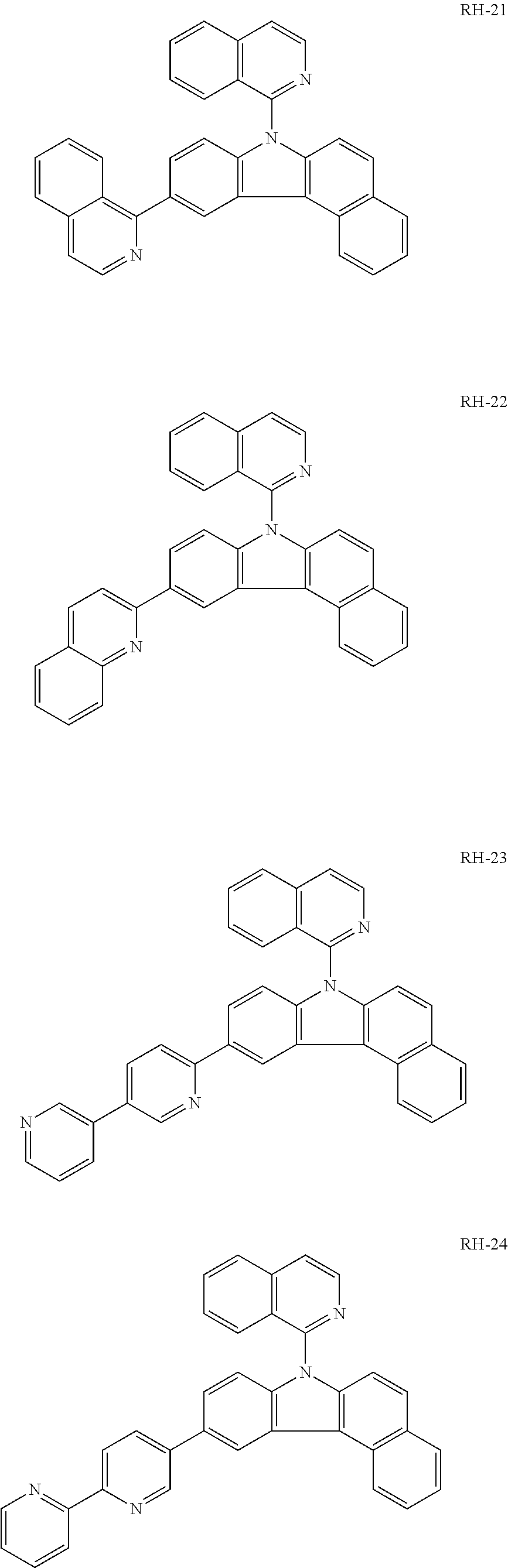


—Second Embodiment—


| TABLE 1 | ||||||||
| elec- | ||||||||
| tric | Current | Power | ||||||
| volt- | cur- | Bright- | effi- | effi- | CIE | CIE | ||
| age | rent | ness | ciency | ciency | IQE | (X) | (Y) | |
| Ex. 1 | 6.0 | 0.9 | 1170 | 11.7 | 6.1 | 15.8 | 0.648 | 0.339 |
| Ex. 2 | 5.5 | 0.9 | 1185 | 11.8 | 6.8 | 16.6 | 0.650 | 0.340 |
| Ex. 3 | 5.3 | 0.9 | 1250 | 12.5 | 7.4 | 17.1 | 0.649 | 0.336 |
| Ex. 4 | 5.4 | 0.9 | 1231 | 12.3 | 7.2 | 16.9 | 0.651 | 0.331 |
| Ex. 5 | 6.5 | 0.9 | 762 | 7.6 | 3.7 | 10.8 | 0.649 | 0.336 |
| Com. 1 | 7.5 | 0.9 | 780 | 7.8 | 3.3 | 10.4 | 0.659 | 0.329 |


| TABLE 2 | ||||||||
| elec- | ||||||||
| tric | Current | Power | ||||||
| volt- | cur- | Bright- | effi- | effi- | CIE | CIE | ||
| age | rent | ness | ciency | ciency | IQE | (X) | (Y) | |
| Ex. 6 | 5.9 | 0.9 | 1180 | 11.8 | 6.3 | 15.8 | 0.649 | 0.338 |
| Ex. 7 | 5.7 | 0.9 | 1195 | 11.9 | 6.6 | 16.6 | 0.650 | 0.340 |
| Ex. 8 | 5.6 | 0.9 | 1260 | 12.6 | 7.1 | 17.1 | 0.650 | 0.336 |
| Ex. 9 | 5.5 | 0.9 | 1241 | 12.4 | 7.1 | 16.9 | 0.651 | 0.330 |
| Ex. 10 | 6.5 | 0.9 | 772 | 7.7 | 3.7 | 10.8 | 0.650 | 0.336 |
| Com. 2 | 7.5 | 0.9 | 780 | 7.8 | 3.3 | 10.4 | 0.659 | 0.329 |
Claims (16)


Applications Claiming Priority (2)
| Application Number | Priority Date | Filing Date | Title |
|---|---|---|---|
| KR10-2012-0153125 | 2012-12-26 | ||
| KR1020120153125A KR102067415B1 (en) | 2012-12-26 | 2012-12-26 | Red Phosphorescent Host Material and Organic Electroluminescent Device Using the Same |
Publications (2)
| Publication Number | Publication Date |
|---|---|
| US20140175402A1 US20140175402A1 (en) | 2014-06-26 |
| US9543527B2 true US9543527B2 (en) | 2017-01-10 |
Family
ID=50973618
Family Applications (1)
| Application Number | Title | Priority Date | Filing Date |
|---|---|---|---|
| US14/087,277 Active 2035-03-11 US9543527B2 (en) | 2012-12-26 | 2013-11-22 | Red phosphorescent compound and organic light emitting diode device using the same |
Country Status (3)
| Country | Link |
|---|---|
| US (1) | US9543527B2 (en) |
| KR (1) | KR102067415B1 (en) |
| CN (1) | CN103896920B (en) |
Families Citing this family (6)
| Publication number | Priority date | Publication date | Assignee | Title |
|---|---|---|---|---|
| KR101463298B1 (en) * | 2011-04-01 | 2014-11-20 | 주식회사 엘지화학 | New organic light emitting device material and organic light emitting device using the same |
| CN104795507B (en) * | 2015-04-16 | 2017-03-22 | 京东方科技集团股份有限公司 | Organic light-emitting device, method for manufacturing same and electronic equipment |
| KR101789672B1 (en) | 2015-09-25 | 2017-10-25 | 한국생산기술연구원 | New organic light emitting compound having highly solubility, and process for the preparation organic electroluminescent device comprising the same compound |
| CN109912565A (en) * | 2017-12-13 | 2019-06-21 | 江苏三月光电科技有限公司 | A compound with cyanoazepine as the core and its application in organic electroluminescent devices |
| WO2019194617A1 (en) * | 2018-04-05 | 2019-10-10 | 주식회사 엘지화학 | Amine compound and organic light emitting diode comprising same |
| CN117720557A (en) * | 2023-12-04 | 2024-03-19 | 安徽省华显新材料科技有限公司 | An electron injection material and OLED organic electroluminescent device |
Citations (1)
| Publication number | Priority date | Publication date | Assignee | Title |
|---|---|---|---|---|
| WO2010114264A2 (en) | 2009-03-31 | 2010-10-07 | Dow Advanced Display Materials,Ltd. | Novel organic electroluminescent compounds and organic electroluminescent device using the same |
Family Cites Families (3)
| Publication number | Priority date | Publication date | Assignee | Title |
|---|---|---|---|---|
| KR20110013220A (en) * | 2009-07-31 | 2011-02-09 | 다우어드밴스드디스플레이머티리얼 유한회사 | Novel organic light emitting compound and organic electroluminescent device comprising same |
| KR101431644B1 (en) * | 2009-08-10 | 2014-08-21 | 롬엔드하스전자재료코리아유한회사 | Novel organic electroluminescent compounds and organic electroluminescent devices containing them |
| KR20120081539A (en) * | 2011-01-11 | 2012-07-19 | (주)씨에스엘쏠라 | Organic light compound and organic light device using the same |
-
2012
- 2012-12-26 KR KR1020120153125A patent/KR102067415B1/en active Active
-
2013
- 2013-11-22 US US14/087,277 patent/US9543527B2/en active Active
- 2013-11-29 CN CN201310627623.7A patent/CN103896920B/en active Active
Patent Citations (1)
| Publication number | Priority date | Publication date | Assignee | Title |
|---|---|---|---|---|
| WO2010114264A2 (en) | 2009-03-31 | 2010-10-07 | Dow Advanced Display Materials,Ltd. | Novel organic electroluminescent compounds and organic electroluminescent device using the same |
Non-Patent Citations (1)
| Title |
|---|
| Office Action issued in Chinese Patent Application No. 201310627623.7, mailed Apr. 23, 2015, 10 pages. |
Also Published As
| Publication number | Publication date |
|---|---|
| KR20140083412A (en) | 2014-07-04 |
| CN103896920A (en) | 2014-07-02 |
| KR102067415B1 (en) | 2020-01-17 |
| CN103896920B (en) | 2016-08-17 |
| US20140175402A1 (en) | 2014-06-26 |
Similar Documents
| Publication | Publication Date | Title |
|---|---|---|
| US10319922B2 (en) | Compound for organic electronic element, organic electronic element comprising the same and electronic device thereof | |
| US8962158B2 (en) | Material having indolocarbazole compound for phosphorescent light-emitting element and organic electroluminescent element using the same | |
| US8906521B2 (en) | Organic electroluminescent device having triptycene derivative material | |
| US9233923B2 (en) | Organic compounds for organic electronic devices and terminals | |
| US9461250B2 (en) | Organic electroluminescent device | |
| US8389131B2 (en) | Material for use in phosphorescent device and organic electroluminescent device using same | |
| CN102754237B (en) | Organic electroluminescent element | |
| US9985219B2 (en) | Organic electroluminescent element | |
| US9260433B2 (en) | Organic electroluminescent device | |
| US7737627B2 (en) | Fluorene-based compound and organic electroluminescent display device using the same | |
| US12016243B2 (en) | Condensed cyclic compound and organic light emitting device comprising same | |
| US20220352473A1 (en) | Polycyclic compound and organic light emitting diode comprising same | |
| US8722208B2 (en) | Organic electroluminescent device | |
| US20180339967A1 (en) | Compound for organic optoelectronic device, organic optoelectronic device and display apparatus | |
| US9543527B2 (en) | Red phosphorescent compound and organic light emitting diode device using the same | |
| KR20140015202A (en) | Organic electroluminescent compound comprising acridine derivative and organic electroluminescent device comprising same | |
| KR20150124911A (en) | Novel compound and organic electroluminescent device comprising same | |
| CN105745301B (en) | Novel light-emitting compound and organic light-emitting element including the same | |
| KR20150058082A (en) | Novel electroluminescent compound and organic electroluminescent device comprising same | |
| KR20150058080A (en) | Novel electroluminescent compound and organic electroluminescent device comprising same | |
| KR20170035344A (en) | New compound and organic light emitting device comprising the same | |
| CN105473594A (en) | Novel organic compound and organic light-emitting device comprising same | |
| US8987472B2 (en) | N-cycloalkylalkyl triscarbazoles | |
| KR20150095208A (en) | Novel hole injecting· hole-transporting compound and organic electroluminescent device comprising same | |
| KR20150065146A (en) | Novel compound and organic electroluminescent device comprising same |
Legal Events
| Date | Code | Title | Description |
|---|---|---|---|
| AS | Assignment |
Owner name: LG DISPLAY CO.,, KOREA, REPUBLIC OF Free format text: ASSIGNMENT OF ASSIGNORS INTEREST;ASSIGNOR:JEONG, HYUN-CHEOL;REEL/FRAME:031659/0676 Effective date: 20131029 |
|
| AS | Assignment |
Owner name: LG DISPLAY CO., LTD., KOREA, REPUBLIC OF Free format text: CORRECTIVE ASSIGNMENT TO CORRECT THE ASSIGNEE NAME PREVIOUSLY RECORDED AT REEL: 031659 FRAME: 0676. ASSIGNOR(S) HEREBY CONFIRMS THE ASSIGNMENT;ASSIGNOR:JEONG, HYUN-CHEOL;REEL/FRAME:039970/0723 Effective date: 20131029 |
|
| FEPP | Fee payment procedure |
Free format text: PAYOR NUMBER ASSIGNED (ORIGINAL EVENT CODE: ASPN); ENTITY STATUS OF PATENT OWNER: LARGE ENTITY |
|
| STCF | Information on status: patent grant |
Free format text: PATENTED CASE |
|
| MAFP | Maintenance fee payment |
Free format text: PAYMENT OF MAINTENANCE FEE, 4TH YEAR, LARGE ENTITY (ORIGINAL EVENT CODE: M1551); ENTITY STATUS OF PATENT OWNER: LARGE ENTITY Year of fee payment: 4 |
|
| MAFP | Maintenance fee payment |
Free format text: PAYMENT OF MAINTENANCE FEE, 8TH YEAR, LARGE ENTITY (ORIGINAL EVENT CODE: M1552); ENTITY STATUS OF PATENT OWNER: LARGE ENTITY Year of fee payment: 8 |