US9542731B2 - Apparatus for increasing sharpness - Google Patents
Apparatus for increasing sharpness Download PDFInfo
- Publication number
- US9542731B2 US9542731B2 US14/650,044 US201314650044A US9542731B2 US 9542731 B2 US9542731 B2 US 9542731B2 US 201314650044 A US201314650044 A US 201314650044A US 9542731 B2 US9542731 B2 US 9542731B2
- Authority
- US
- United States
- Prior art keywords
- image
- synthesize
- sharpness
- unit
- gain
- Prior art date
- Legal status (The legal status is an assumption and is not a legal conclusion. Google has not performed a legal analysis and makes no representation as to the accuracy of the status listed.)
- Active
Links
Images


Classifications
-
- G—PHYSICS
- G06—COMPUTING OR CALCULATING; COUNTING
- G06T—IMAGE DATA PROCESSING OR GENERATION, IN GENERAL
- G06T5/00—Image enhancement or restoration
- G06T5/73—Deblurring; Sharpening
-
- G06T5/003—
-
- G06K9/48—
-
- G—PHYSICS
- G06—COMPUTING OR CALCULATING; COUNTING
- G06T—IMAGE DATA PROCESSING OR GENERATION, IN GENERAL
- G06T5/00—Image enhancement or restoration
- G06T5/10—Image enhancement or restoration using non-spatial domain filtering
-
- G06T7/0085—
-
- G—PHYSICS
- G06—COMPUTING OR CALCULATING; COUNTING
- G06T—IMAGE DATA PROCESSING OR GENERATION, IN GENERAL
- G06T7/00—Image analysis
- G06T7/10—Segmentation; Edge detection
- G06T7/13—Edge detection
-
- H—ELECTRICITY
- H04—ELECTRIC COMMUNICATION TECHNIQUE
- H04N—PICTORIAL COMMUNICATION, e.g. TELEVISION
- H04N23/00—Cameras or camera modules comprising electronic image sensors; Control thereof
- H04N23/80—Camera processing pipelines; Components thereof
- H04N23/81—Camera processing pipelines; Components thereof for suppressing or minimising disturbance in the image signal generation
-
- H—ELECTRICITY
- H04—ELECTRIC COMMUNICATION TECHNIQUE
- H04N—PICTORIAL COMMUNICATION, e.g. TELEVISION
- H04N5/00—Details of television systems
- H04N5/14—Picture signal circuitry for video frequency region
- H04N5/20—Circuitry for controlling amplitude response
- H04N5/205—Circuitry for controlling amplitude response for correcting amplitude versus frequency characteristic
- H04N5/208—Circuitry for controlling amplitude response for correcting amplitude versus frequency characteristic for compensating for attenuation of high frequency components, e.g. crispening, aperture distortion correction
-
- G—PHYSICS
- G06—COMPUTING OR CALCULATING; COUNTING
- G06T—IMAGE DATA PROCESSING OR GENERATION, IN GENERAL
- G06T2207/00—Indexing scheme for image analysis or image enhancement
- G06T2207/20—Special algorithmic details
- G06T2207/20004—Adaptive image processing
- G06T2207/20012—Locally adaptive
-
- G—PHYSICS
- G06—COMPUTING OR CALCULATING; COUNTING
- G06T—IMAGE DATA PROCESSING OR GENERATION, IN GENERAL
- G06T2207/00—Indexing scheme for image analysis or image enhancement
- G06T2207/20—Special algorithmic details
- G06T2207/20172—Image enhancement details
- G06T2207/20192—Edge enhancement; Edge preservation
Definitions
- the teachings in accordance with the exemplary embodiments of this present disclosure generally relate to an apparatus for increasing sharpness of an image.
- an image process system goes through a process of correcting a distorted image because a distortion exists on an image obtained through an image sensor.
- an apparatus for increasing sharpness comprising: a sensor unit configured to obtain an image; a detection unit configured to detect an edge component of the image; and a synthesize unit configured to synthesize different sharpness gains according to a position of the image to an edge component detected by the detection unit.
- the apparatus may further comprise an output unit configured to output a final image using an edge component improved in sharpness by the synthesize unit.
- the synthesize unit may be configured to synthesize a smallest sharpness gain toward a center of the image.
- the synthesize unit may be configured to synthesize a larger sharpness gain toward a periphery of the image.
- the synthesize unit may be configured to synthesize a sharpness gain discretely increasing from a center of the image toward a periphery of the image.
- the synthesize unit may be configured to synthesize a sharpness gain continuously increasing from a center of the image toward a periphery of the image.
- the synthesize unit may be configured to synthesize a Laplacian type sharpness gain to the image.
- an apparatus for increasing sharpness comprising: a sensor unit configured to obtain an image; a detection unit configured to detect an edge component of the image; a filter unit configured to divide the edge component to a plurality of frequency bands; a plurality of first synthesize units configured to synthesize respectively different sharpness gains to the edge components extracted to the plurality of frequency bands; and a plurality of second synthesize units configured to synthesize the edge components outputted by the plurality of synthesizers.
- the apparatus may further comprise an output unit configured to output a final image using an edge component improved in sharpness by the synthesize unit.
- the filter unit may include a plurality of BPFs (Band Pass Filters) each passing a respectively different frequency band.
- BPFs Band Pass Filters
- the first synthesizer may be configured to synthesize a Laplacian type sharpness gain to the image.
- the apparatus for increasing sharpness can synthesize larger sharpness gains toward a periphery of an image compared to sharpness gains toward a center of an image to restrict generation of noise and to restrict an excessive increase in sharpness toward a center of an image as well.
- edge components of an image can be divided into each frequency band, and respective sharpness gains can be synthesized according to relevant frequency bands to reduce generation of noise, and to increase sharpness for each frequency band of edge components.
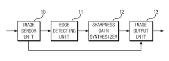
- FIG. 1 is a schematic block diagram illustrating an apparatus for increasing sharpness according to a first exemplary embodiment of the present invention.
- FIGS. 2 a to 2 c are schematic views illustrating an image outputted from each constituent element of FIG. 1 according to an exemplary embodiment of the present invention.
- FIG. 3 is a schematic view illustrating a method of synthesizing, by a sharpness gain synthesize unit, a sharpness gain relative to an edge according to an exemplary embodiment of the present invention.
- FIGS. 4 a and 4 b are schematic views illustrating sharpness gains discretely and continuously increasing from a center of an image.
- FIG. 5 is a schematic block diagram illustrating an apparatus for increasing sharpness according to a second exemplary embodiment of the present invention.
- FIG. 6 is a schematic view illustrating an edge component for each frequency band.
- FIG. 1 is a schematic block diagram illustrating an apparatus for increasing sharpness according to a first exemplary embodiment of the present invention
- FIGS. 2 a to 2 c are schematic views illustrating an image outputted from each constituent element of FIG. 1 according to an exemplary embodiment of the present invention.
- the apparatus for increasing sharpness (hereinafter referred to as “apparatus”) according to a first exemplary embodiment of the present invention comprises an image sensor ( 10 ), an edge detection unit ( 11 ), a sharpness gain synthesize unit ( 12 ) and an image output unit ( 13 ).
- the image sensor ( 10 ) obtains an image signal received from a camera (not shown) configured to photograph an image.
- the image sensor ( 10 ) may be a camera sensor of a CCD (Charge Coupled Device) type or a CMOS (Complementary Metal Oxide Semiconductor) type camera sensor, for example.
- CCD Charge Coupled Device
- CMOS Complementary Metal Oxide Semiconductor
- FIG. 2 a illustrates an image obtained by the image sensor ( 10 ).
- the edge detection unit ( 11 ) detects an edge component of the image obtained by the image sensor ( 10 ). For example, when the image sensor ( 10 ) outputs RGB (red, green, blue) images, the edge detection unit ( 11 ) may detect a brightness (luminance) component (Y) from the RGB images, where the brightness component may be an edge component.
- RGB red, green, blue
- Y brightness
- FIG. 2 b illustrates an edge detected from the image of FIG. 2 a by the edge detection unit ( 11 ).
- FIG. 3 is a schematic view illustrating a method of synthesizing, by the sharpness gain synthesize unit ( 12 ), a sharpness gain of an edge according to an exemplary embodiment of the present invention, where (a) expresses an edge detected by the edge detection unit ( 12 ), (b) illustrates a sharpness gain, and (c) illustrates a synthesized result of (a) and (b). It can be noted from FIG. 3 that edge of an image is further sharpened by synthesize of sharpness gains.
- the sharpness gain synthesize unit ( 12 ) may differently synthesize the sharpness gains in response to positions of the images. That is, the sharpness gain synthesize unit ( 12 ) may divide an image to a plurality of concentric circles (A), as shown in FIG. 2 c , and provide a separate sharpness gain to each edge of the image inside the concentric circles, whereby respectively different sharpness gains can be provided in response to positions of the image. To be more specific, smallest sharpness gains may be synthesized for a center of the image and largest sharpness gains may be synthesized for a periphery of the image.
- Sharpness gains which discretely increase from a center of an image or which continuously increase from a center of an image, can be synthesized using the sharpness gain synthesize unit ( 12 ) according to an exemplary embodiment of the present disclosure that provides a separate gain to each concentric circle to the image as shown in FIG. 2 c.
- FIGS. 4 a and 4 b are schematic views illustrating sharpness gains discretely and continuously increasing from a center of an image, where a gain set along a diagonal line (B) of FIG. 2 c is illustrated, for example.
- a gain set along a diagonal line (B) of FIG. 2 c is illustrated, for example.
- FIGS. 4 a and 4 b it can be noted that smallest sharpness gains are provided toward the center of the image for both FIGS. 4 a and 4 b , and largest sharpness gains are provided toward the periphery of the image.
- the image output unit ( 13 ) may output a final image using edge components improved in sharpness. That is, the sharpness-improved edge image is a brightness component, and RGB images can be outputted using the brightness component.
- the conversion of brightness image to RGB images is well known to the skilled in the art, such that no further explanation thereto is made.
- the sharpness gain synthesize unit ( 12 ) may use a Laplacian type sharpness gain.
- a Laplacian mask is used for detecting an edge of an image, which can be expressed by the following Equation 1.
- G 2 f [f ( x+ 1, y )+ f ( x ⁇ 1, y )+ f ( x,y+ 1)+ f ( x,y ⁇ 1)] [Math FIG. 1]
- a gain may be expressed by the following Equation when using a Laplacian mask.
- a center constant of the Laplacian mask is negative for an upper case of the above Equation 2, and positive for a lower case of the above Equation 2.
- the sharpness gain synthesize unit ( 12 ) has an original image at a center of an image and has a result as expressed in Equation 2 toward a periphery of an image.
- a gain using the Laplacian used by the sharpness gain synthesize unit ( 12 ) according to an exemplary embodiment of the present disclosure may be expressed by the following Equation 3.
- the apparatus for increasing sharpness can synthesize larger sharpness gains toward a periphery of an image compared to sharpness gains toward a center of an image to restrict generation of noise and to restrict an excessive increase in sharpness toward a center of an image as well.
- FIG. 5 is a schematic block diagram illustrating an apparatus for increasing sharpness according to a second exemplary embodiment of the present invention.
- the apparatus for increasing sharpness may include an image sensor unit ( 20 ), an edge detection unit ( 21 ), a BPF (Band Pass Filter, 22 ), first, second and third band gain synthesize units ( 23 , 24 , 25 ), a synthesize unit ( 26 ) and an image output unit ( 27 ).
- an image sensor unit 20
- an edge detection unit 21
- a BPF Band Pass Filter
- first, second and third band gain synthesize units 23 , 24 , 25
- a synthesize unit 26
- an image output unit 27
- the image sensor ( 20 ) obtains an image signal received from a camera (not shown) configured to photograph an image.
- the image sensor ( 20 ) may be a camera sensor of a CCD type or a CMOS type camera sensor, for example.
- the present disclosure is not limited thereto, and other devices capable of performing a function similar to the camera sensor may be also used.
- the edge detection unit ( 21 ) detects an edge component of the image obtained by the image sensor ( 20 ). For example, when the image sensor ( 20 ) outputs RGB (red, green, blue) images, the edge detection unit ( 21 ) may detect a brightness (luminance) component (Y) from the RGB images, where the brightness component may be an edge component.
- RGB red, green, blue
- Y brightness
- Methods converting RGB components to YCbCr components are well known in the technical field the present disclosure belongs to, such that no further detailed explanation is provided therein.
- the BPF unit ( 22 ) may extract a particular frequency band from an edge of an image detected by the edge detection unit ( 21 ). That is, the BPF unit ( 22 ) may separate from the edge of the image to a high band edge component, a middle band edge component and a low band edge component.
- the apparatus for increasing sharpness according to the second exemplary embodiment of the present invention illustrates using one BFP, it would be obvious that a plurality of BPFs may form a BPF unit.
- a high band, a middle band and a low band are determined by attributes of an image, which are a relative concept, such that the present disclosure is not restricted to particular bands.
- the first, second and third band gain synthesize units ( 23 , 24 , 25 ) synthesize edge images of particular band received from the BFP unit ( 22 ) by respectively providing a sharpness gain thereto.
- an edge detected by the edge detection unit ( 21 ) is classified to predetermined frequency bands, and separate sharpness gains are synthesized on edge components of particular frequency bands according to an exemplary embodiment of the present disclosure, whereby sharpness for each predetermined frequency band can be increased and noise can be reduced.
- FIG. 6 is a schematic view illustrating an edge component for each frequency band, where (a) is an edge component of an image detected by the edge detection unit ( 21 ), and (b) (c) and (d) are edge components separated by the BPF unit ( 22 ) for each band.
- the exemplary embodiment of the present disclosure can individually extract a frequency band for each image by checking a frequency band of an edge component in an image.
- a frequency band may be determined by an image.
- the synthesize unit ( 26 ) can synthesize edge components of an image in which sharpness gains are respectively synthesized for each band, and the image output unit ( 27 ) can output final RGB images by using a sharpness-increased edge component.
- the apparatus for increasing sharpness divides an edge component to each frequency band, and applies a separate sharpness gain to each band.
- a gain equation used by the first, second and third band gain synthesize units ( 23 , 24 , 25 ) may be expressed by the following Equation, when the apparatus for increasing sharpness according to the second exemplary embodiment of the present disclosure uses the Laplacian.
- G i G ( G i-1 , ⁇ i ) [Math FIG. 5]
- G 0 defines an original image ‘f’
- ⁇ ’ is a constant that affects division of band area
- Equation 4 may be expressed by the following equation if an edge is divided to three bands as in the second exemplary embodiment of the present disclosure.
- g ⁇ ( x , y ) G 2 ⁇ ( x , y ) + L 0 ⁇ ( x , y ) + L 1 ⁇ ( x , y ) - ⁇ ⁇ ⁇ G 2 ⁇ ( G 2 ⁇ ( x , y ) + ⁇ 0 ⁇ L 0 ⁇ ( x , y ) + ⁇ 1 ⁇ L 1 ⁇ ( x , y ) ) ⁇ x 2 + y 2 r [ Math ⁇ ⁇ Figure ⁇ ⁇ 6 ]
- ⁇ is an improved level of an entire sharpness, where, an image appears as if the image has not improved if ‘ ⁇ ’ is too small, and the high frequency components of edge components or noise components may be highlighted if ‘ ⁇ ’ is too large.
- ⁇ is a constant indicating a weight for each band.
- ⁇ 1 indicates a gain for a middle frequency band, if a gain of low band is defined as 1 according to the exemplary embodiment of the present disclosure
- ⁇ 2 is a gain of a high frequency band, if a gain of low band is defined as 1. If ⁇ 1, edge components or noise components in high frequency components are prevented from being highlighted, and if ⁇ >1, the edge components or noise components in high frequency components are rather amplified.
- appropriate selection of ⁇ and ⁇ is required depending on images.
- the above cases are limited to those using the Laplacian, and the apparatus for increasing sharpness according to an exemplary embodiment of the present disclosure may synthesize gains with edge components of an image using other methods than the Laplacian.
- the apparatus for increasing sharpness can divide edge components of an image to each frequency band, and synthesize each separate sharpness gain according to a relevant frequency band to reduce generation of noise and increase sharpness of each frequency band.
- the apparatus for increasing sharpness can synthesize larger sharpness gains toward a periphery of an image compared to sharpness gains toward a center of an image to restrict generation of noise and to restrict an excessive increase in sharpness toward a center of an image as well.
- edge components of an image can be divided into each frequency band, and respective sharpness gains can be synthesized according to relevant frequency bands to reduce generation of noise, and to increase sharpness for each frequency band of edge components.
Landscapes
- Engineering & Computer Science (AREA)
- Physics & Mathematics (AREA)
- General Physics & Mathematics (AREA)
- Theoretical Computer Science (AREA)
- Multimedia (AREA)
- Signal Processing (AREA)
- Computer Vision & Pattern Recognition (AREA)
- Image Processing (AREA)
- Studio Devices (AREA)
Abstract
Description
G 2 f=[f(x+1,y)+f(x−1,y)+f(x,y+1)+f(x,y−1)] [Math FIG. 1]
G i =G(G i-1,σi) [Math FIG. 5]
Claims (9)
Applications Claiming Priority (4)
| Application Number | Priority Date | Filing Date | Title |
|---|---|---|---|
| KR10-2012-0140880 | 2012-12-06 | ||
| KR10-2012-01408806 | 2012-12-06 | ||
| KR1020120140880A KR101986108B1 (en) | 2012-12-06 | 2012-12-06 | Apparatus for increasing sharpness |
| PCT/KR2013/011162 WO2014088314A1 (en) | 2012-12-06 | 2013-12-04 | Apparatus for increasing sharpness |
Publications (2)
| Publication Number | Publication Date |
|---|---|
| US20150302559A1 US20150302559A1 (en) | 2015-10-22 |
| US9542731B2 true US9542731B2 (en) | 2017-01-10 |
Family
ID=50883683
Family Applications (1)
| Application Number | Title | Priority Date | Filing Date |
|---|---|---|---|
| US14/650,044 Active US9542731B2 (en) | 2012-12-06 | 2013-12-04 | Apparatus for increasing sharpness |
Country Status (3)
| Country | Link |
|---|---|
| US (1) | US9542731B2 (en) |
| KR (1) | KR101986108B1 (en) |
| WO (1) | WO2014088314A1 (en) |
Families Citing this family (1)
| Publication number | Priority date | Publication date | Assignee | Title |
|---|---|---|---|---|
| WO2019180634A1 (en) * | 2018-03-23 | 2019-09-26 | Glaxosmithkline Intellectual Property Development Limited | Synthesis of oxazinone-containing bicyclic aromatic and heteroaromatic aldehydes |
Citations (18)
| Publication number | Priority date | Publication date | Assignee | Title |
|---|---|---|---|---|
| US20030218776A1 (en) * | 2002-03-20 | 2003-11-27 | Etsuo Morimoto | Image processor and image processing method |
| US20040057630A1 (en) * | 2002-09-24 | 2004-03-25 | Thomas Schuhrke | Image processing method for automated contrast modification of digital image data |
| US20050025383A1 (en) | 2003-07-02 | 2005-02-03 | Celartem Technology, Inc. | Image sharpening with region edge sharpness correction |
| US20050104974A1 (en) * | 2002-02-12 | 2005-05-19 | Tatsumi Watanabe | Image processing device and image processing method |
| US20060061690A1 (en) * | 2002-05-24 | 2006-03-23 | Gerard De Haan | Unit for and method of sharpness enchancement |
| US20070098295A1 (en) * | 2005-10-27 | 2007-05-03 | Jen-Shi Wu | Edge compensated feature detector and method thereof |
| US7230742B1 (en) * | 1998-10-13 | 2007-06-12 | Seiko Epson Corporation | Image data interpolating apparatus and medium on which data interpolating program is recorded |
| US20080238820A1 (en) * | 2007-03-29 | 2008-10-02 | Otsuka Electronics Co., Ltd | Motion picture image processing system and motion picture image processing method |
| US20090067710A1 (en) * | 2007-09-11 | 2009-03-12 | Samsung Electronics Co., Ltd. | Apparatus and method of restoring an image |
| US20090103831A1 (en) * | 2007-10-17 | 2009-04-23 | Yusuke Nakamura | Image processing apparatus, image processing method, and program therefor |
| US20090115858A1 (en) * | 2007-11-02 | 2009-05-07 | Young-Sin Lee | Apparatus and method for digital image stabilization using object tracking |
| US20090278989A1 (en) | 2008-05-11 | 2009-11-12 | Cheon-Ho Bae | Sharpness enhancing apparatus and method |
| US20090316024A1 (en) | 2006-08-25 | 2009-12-24 | Yo-Hwan Noh | Image edge detection apparatus and method, image sharpness emphasizing apparatus and method, recorded meduim recorded the program performing it |
| US20100182459A1 (en) * | 2009-01-20 | 2010-07-22 | Samsung Electronics Co., Ltd. | Apparatus and method of obtaining high-resolution image |
| US20120007942A1 (en) | 2010-07-06 | 2012-01-12 | Tessera Technologies Ireland Limited | Scene Background Blurring Including Determining A Depth Map |
| US20120033885A1 (en) | 2010-08-06 | 2012-02-09 | Dong-A University Research Foundation For Industry-Academy Cooperation | Apparatus for improving sharpness of image |
| US20120105612A1 (en) * | 2010-11-02 | 2012-05-03 | Olympus Corporation | Imaging apparatus, endoscope apparatus, and image generation method |
| US8228397B2 (en) * | 2006-01-31 | 2012-07-24 | Konica Minolta Holdings, Inc. | Image sensing apparatus and image processing method |
Family Cites Families (2)
| Publication number | Priority date | Publication date | Assignee | Title |
|---|---|---|---|---|
| KR101346084B1 (en) * | 2007-11-23 | 2013-12-31 | 엘지디스플레이 주식회사 | Circuit and method for emphasizing edges appearing in a video picture |
| KR100951254B1 (en) * | 2008-07-18 | 2010-04-02 | 삼성전기주식회사 | Image sharpening enhancer |
-
2012
- 2012-12-06 KR KR1020120140880A patent/KR101986108B1/en active Active
-
2013
- 2013-12-04 US US14/650,044 patent/US9542731B2/en active Active
- 2013-12-04 WO PCT/KR2013/011162 patent/WO2014088314A1/en not_active Ceased
Patent Citations (18)
| Publication number | Priority date | Publication date | Assignee | Title |
|---|---|---|---|---|
| US7230742B1 (en) * | 1998-10-13 | 2007-06-12 | Seiko Epson Corporation | Image data interpolating apparatus and medium on which data interpolating program is recorded |
| US20050104974A1 (en) * | 2002-02-12 | 2005-05-19 | Tatsumi Watanabe | Image processing device and image processing method |
| US20030218776A1 (en) * | 2002-03-20 | 2003-11-27 | Etsuo Morimoto | Image processor and image processing method |
| US20060061690A1 (en) * | 2002-05-24 | 2006-03-23 | Gerard De Haan | Unit for and method of sharpness enchancement |
| US20040057630A1 (en) * | 2002-09-24 | 2004-03-25 | Thomas Schuhrke | Image processing method for automated contrast modification of digital image data |
| US20050025383A1 (en) | 2003-07-02 | 2005-02-03 | Celartem Technology, Inc. | Image sharpening with region edge sharpness correction |
| US20070098295A1 (en) * | 2005-10-27 | 2007-05-03 | Jen-Shi Wu | Edge compensated feature detector and method thereof |
| US8228397B2 (en) * | 2006-01-31 | 2012-07-24 | Konica Minolta Holdings, Inc. | Image sensing apparatus and image processing method |
| US20090316024A1 (en) | 2006-08-25 | 2009-12-24 | Yo-Hwan Noh | Image edge detection apparatus and method, image sharpness emphasizing apparatus and method, recorded meduim recorded the program performing it |
| US20080238820A1 (en) * | 2007-03-29 | 2008-10-02 | Otsuka Electronics Co., Ltd | Motion picture image processing system and motion picture image processing method |
| US20090067710A1 (en) * | 2007-09-11 | 2009-03-12 | Samsung Electronics Co., Ltd. | Apparatus and method of restoring an image |
| US20090103831A1 (en) * | 2007-10-17 | 2009-04-23 | Yusuke Nakamura | Image processing apparatus, image processing method, and program therefor |
| US20090115858A1 (en) * | 2007-11-02 | 2009-05-07 | Young-Sin Lee | Apparatus and method for digital image stabilization using object tracking |
| US20090278989A1 (en) | 2008-05-11 | 2009-11-12 | Cheon-Ho Bae | Sharpness enhancing apparatus and method |
| US20100182459A1 (en) * | 2009-01-20 | 2010-07-22 | Samsung Electronics Co., Ltd. | Apparatus and method of obtaining high-resolution image |
| US20120007942A1 (en) | 2010-07-06 | 2012-01-12 | Tessera Technologies Ireland Limited | Scene Background Blurring Including Determining A Depth Map |
| US20120033885A1 (en) | 2010-08-06 | 2012-02-09 | Dong-A University Research Foundation For Industry-Academy Cooperation | Apparatus for improving sharpness of image |
| US20120105612A1 (en) * | 2010-11-02 | 2012-05-03 | Olympus Corporation | Imaging apparatus, endoscope apparatus, and image generation method |
Also Published As
| Publication number | Publication date |
|---|---|
| US20150302559A1 (en) | 2015-10-22 |
| KR20140073123A (en) | 2014-06-16 |
| WO2014088314A1 (en) | 2014-06-12 |
| KR101986108B1 (en) | 2019-06-05 |
Similar Documents
| Publication | Publication Date | Title |
|---|---|---|
| US10819947B2 (en) | Apparatus and method for processing image signal, imaging apparatus, and method for displaying image | |
| US10699395B2 (en) | Image processing device, image processing method, and image capturing device | |
| US10148926B2 (en) | Imaging apparatus and image processing method of thereof | |
| US8938121B2 (en) | Method and apparatus for processing image | |
| US8363123B2 (en) | Image pickup apparatus, color noise reduction method, and color noise reduction program | |
| US8274583B2 (en) | Radially-based chroma noise reduction for cameras | |
| US9324153B2 (en) | Depth measurement apparatus, image pickup apparatus, depth measurement method, and depth measurement program | |
| EP2523160A1 (en) | Image processing device, image processing method, and program | |
| EP1528797A2 (en) | Image processing apparatus, image-taking system and image processing method | |
| US9025903B2 (en) | Image processing device and image processing method | |
| US8774551B2 (en) | Image processing apparatus and image processing method for reducing noise | |
| JP2010525470A (en) | A technique for adjusting effects that apply a kernel to a signal to achieve the desired effect on the signal | |
| US8643743B2 (en) | Image processing apparatus and method | |
| US9083900B2 (en) | Lens shading correction system | |
| US20110085729A1 (en) | De-noising method and related apparatus for image sensor | |
| KR20130000827A (en) | A method for edge enhancement of image | |
| US8559745B2 (en) | Image signal processor and method for image enhancement | |
| US9542731B2 (en) | Apparatus for increasing sharpness | |
| US11593918B1 (en) | Gradient-based noise reduction | |
| US7710474B2 (en) | Luminance signal processing device | |
| US20130016905A1 (en) | Method and apparatus for correcting color distortion | |
| US20240354917A1 (en) | Method for detecting (recognizing) the fact of presenting a digital copy of a document in the form of a screen capture | |
| US20170206631A1 (en) | Image processing unit, imaging device, computer-readable medium, and image processing method | |
| US9183453B2 (en) | Banding noise detector for digital images | |
| JP2019004281A (en) | Image processing device |
Legal Events
| Date | Code | Title | Description |
|---|---|---|---|
| AS | Assignment |
Owner name: LG INNOTEK CO., LTD., KOREA, REPUBLIC OF Free format text: ASSIGNMENT OF ASSIGNORS INTEREST;ASSIGNOR:LEE, SANG YONG;REEL/FRAME:035793/0877 Effective date: 20150527 |
|
| FEPP | Fee payment procedure |
Free format text: PAYOR NUMBER ASSIGNED (ORIGINAL EVENT CODE: ASPN); ENTITY STATUS OF PATENT OWNER: LARGE ENTITY |
|
| STCF | Information on status: patent grant |
Free format text: PATENTED CASE |
|
| MAFP | Maintenance fee payment |
Free format text: PAYMENT OF MAINTENANCE FEE, 4TH YEAR, LARGE ENTITY (ORIGINAL EVENT CODE: M1551); ENTITY STATUS OF PATENT OWNER: LARGE ENTITY Year of fee payment: 4 |
|
| MAFP | Maintenance fee payment |
Free format text: PAYMENT OF MAINTENANCE FEE, 8TH YEAR, LARGE ENTITY (ORIGINAL EVENT CODE: M1552); ENTITY STATUS OF PATENT OWNER: LARGE ENTITY Year of fee payment: 8 |