US9537785B2 - Link aggregation group (LAG) link allocation - Google Patents
Link aggregation group (LAG) link allocation Download PDFInfo
- Publication number
- US9537785B2 US9537785B2 US14/460,340 US201414460340A US9537785B2 US 9537785 B2 US9537785 B2 US 9537785B2 US 201414460340 A US201414460340 A US 201414460340A US 9537785 B2 US9537785 B2 US 9537785B2
- Authority
- US
- United States
- Prior art keywords
- lag
- packets
- information
- network node
- path identifiers
- Prior art date
- Legal status (The legal status is an assumption and is not a legal conclusion. Google has not performed a legal analysis and makes no representation as to the accuracy of the status listed.)
- Active, expires
Links
- 230000002776 aggregation Effects 0.000 title claims abstract description 11
- 238000004220 aggregation Methods 0.000 title claims abstract description 11
- 238000000034 method Methods 0.000 claims abstract description 40
- 238000012423 maintenance Methods 0.000 claims description 7
- 238000012544 monitoring process Methods 0.000 claims description 5
- ORQBXQOJMQIAOY-UHFFFAOYSA-N nobelium Chemical compound [No] ORQBXQOJMQIAOY-UHFFFAOYSA-N 0.000 description 9
- 238000010586 diagram Methods 0.000 description 8
- 230000006870 function Effects 0.000 description 5
- 230000008569 process Effects 0.000 description 5
- 238000012545 processing Methods 0.000 description 2
- 230000004044 response Effects 0.000 description 2
- 230000003068 static effect Effects 0.000 description 2
- 230000008859 change Effects 0.000 description 1
- 238000005516 engineering process Methods 0.000 description 1
- 239000000835 fiber Substances 0.000 description 1
- 238000000786 liquid-assisted grinding Methods 0.000 description 1
- 230000007246 mechanism Effects 0.000 description 1
- 238000005457 optimization Methods 0.000 description 1
- 238000012546 transfer Methods 0.000 description 1
Images


Classifications
-
- H—ELECTRICITY
- H04—ELECTRIC COMMUNICATION TECHNIQUE
- H04L—TRANSMISSION OF DIGITAL INFORMATION, e.g. TELEGRAPHIC COMMUNICATION
- H04L47/00—Traffic control in data switching networks
- H04L47/10—Flow control; Congestion control
- H04L47/41—Flow control; Congestion control by acting on aggregated flows or links
-
- H—ELECTRICITY
- H04—ELECTRIC COMMUNICATION TECHNIQUE
- H04L—TRANSMISSION OF DIGITAL INFORMATION, e.g. TELEGRAPHIC COMMUNICATION
- H04L45/00—Routing or path finding of packets in data switching networks
- H04L45/24—Multipath
- H04L45/245—Link aggregation, e.g. trunking
-
- Y—GENERAL TAGGING OF NEW TECHNOLOGICAL DEVELOPMENTS; GENERAL TAGGING OF CROSS-SECTIONAL TECHNOLOGIES SPANNING OVER SEVERAL SECTIONS OF THE IPC; TECHNICAL SUBJECTS COVERED BY FORMER USPC CROSS-REFERENCE ART COLLECTIONS [XRACs] AND DIGESTS
- Y02—TECHNOLOGIES OR APPLICATIONS FOR MITIGATION OR ADAPTATION AGAINST CLIMATE CHANGE
- Y02D—CLIMATE CHANGE MITIGATION TECHNOLOGIES IN INFORMATION AND COMMUNICATION TECHNOLOGIES [ICT], I.E. INFORMATION AND COMMUNICATION TECHNOLOGIES AIMING AT THE REDUCTION OF THEIR OWN ENERGY USE
- Y02D30/00—Reducing energy consumption in communication networks
- Y02D30/50—Reducing energy consumption in communication networks in wire-line communication networks, e.g. low power modes or reduced link rate
Definitions
- the subject matter described herein relates to processing information. More specifically, the subject matter relates to methods, systems, and computer readable media for link aggregation group (LAG) link allocation.
- LAG link aggregation group
- Link aggregation generally refers to any technique that aggregates or combines multiple network connections (e.g., links or ports) into one virtual network connection or a link aggregation group (LAG).
- LAG link aggregation group
- a network switch may provide data to a server via two LAG links associated with a LAG, where the combined throughput of the LAG links is greater than either of the individual LAG links.
- a network element such as a network switch, may be configured to provide the packets via one or more LAG links.
- issues arise when attempting to use or allocate the LAG efficiently.
- conventional LAG link allocation is typically based on a flow tuple hash or other methods that fail to effectively load balance or load share flows (e.g., sessions or related packets) among LAG links.
- conventional LAG link allocation techniques fail to ensure that LAG links are not overutilized or underutilized.
- Another problem with conventional LAG implementations is that conventional LAG implementations typically require all links in a LAG be the same speed and have other similar characteristics, such as latency.
- the method includes status information associated with a LAG.
- the method also includes at a first network node, utilizing the status information to set path identifiers in packets for controlling LAG allocation.
- the method further includes at a second network node separate from the first network node, receiving the packets and allocating LAG links to the packets based on the path identifiers.
- the system includes a LAG controller configured to monitor status information associated with a LAG.
- the system also includes a first network node configured to utilize the status information to set path identifiers in packets for controlling LAG allocation and a second network node separate from the first network node.
- the second network node is configured to receive the packets and to allocate LAG links to the packets based on the path identifiers.
- the subject matter described herein may be implemented in software in combination with hardware and/or firmware.
- the subject matter described herein may be implemented in software executed by a processor.
- the subject matter described herein may be implemented using a computer readable medium having stored thereon computer executable instructions that when executed by the processor of a computer control the computer to perform steps.
- Exemplary computer readable media suitable for implementing the subject matter described herein include non-transitory devices, such as disk memory devices, chip memory devices, programmable logic devices, and application specific integrated circuits.
- a computer readable medium that implements the subject matter described herein may be located on a single device or computing platform or may be distributed across multiple devices or computing platforms.
- node refers to a physical computing platform including one or more processors and memory.
- the terms “function” or “module” refer to hardware, firmware, or software in combination with hardware and/or firmware for implementing features described herein.
- a link refers to any path, route, or type(s) of connection between devices.
- a link may include one or more communications nodes, networks, or media, such as a wire, cable, fiber optics, radio, or other medium.
- a link may also include a trunk and/or logical connection.
- link aggregation group refers to a group of links, a related link aggregation technique, and/or a multi-path technique for connecting multiple devices.
- a LAG may involve an equal-cost multi-path routing technique or other multi-path technology for providing communications between two or more network nodes.
- the two or more network nodes may be associated with different data centers, networks, and/or multiple network operators interconnecting them.
- FIG. 1 is a diagram illustrating an exemplary network for LAG link allocation according to an embodiment of the subject matter described herein;
- FIGS. 2A and 2B are diagrams illustrating exemplary data associated with LAG link allocation according to an embodiment of the subject matter described herein;
- FIG. 3 is a diagram illustrating exemplary data indicating associations between virtual local area network (VLAN) identifiers and LAG links according to an embodiment of the subject matter described herein; and
- VLAN virtual local area network
- FIG. 4 is a diagram illustrating an exemplary process for indirect LAG link allocation according to an embodiment of the subject matter described herein.
- LAG link allocation techniques use hashing functions that generate hash values based on packet header information, e.g., a source address, a destination address, a source port number, a destination port number, and/or an application protocol. For example, every packet in a flow may include packet header information that outputs to the same hash value. In this example, the hash value may be associated with a particular LAG link. While packets of a given flow may be related to the same hash value, other packets may also include packet header information that when used by a hashing function generates the same hash value and, therefore, multiple flows may be associated with the same link. Hence, conventional LAG link allocation techniques that use hashing functions do not prevent LAG links from being overutilized or underutilized.
- a computing platform e.g., a device or a node
- a module e.g., a field-programmable gateway array (FPGA), an application-specific integrated circuit (ASIC), or software executing on a processor
- a network element e.g., a network switch, a network router, or an endpoint
- may receive status information associated with a LAG e.g., link utilization information, error rate information, and/or maintenance or projected maintenance information
- a LAG controller or other entity such as a software defined network (SDN) controller or a network management system.
- SDN software defined network
- the network element may modify, using the status information, values (e.g., in a load balancing hash table) that determines path identifiers to include in packets, where each of the path identifiers (e.g., virtual local area network (VLAN) identifier or a multiprotocol label switching (MPLS) label) indicates a particular LAG link for sending a corresponding packet.
- values e.g., in a load balancing hash table
- MPLS multiprotocol label switching
- an exemplary computing platform or module may use current utilization rates of individual LAG links to effectively load balance (e.g., load share) packets among LAG links.
- load balance e.g., load share
- load balancing mechanisms or related lookup information at a network element associated with a LAG e.g., a network switch connected to LAG links
- the associations between path identifiers and LAG links may be substantially static and/or have a one to one ratio.
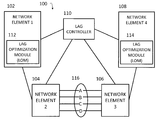
- FIG. 1 is a diagram illustrating an exemplary network 100 for LAG link allocation according to an embodiment of the subject matter described herein.
- Network 100 may represent any suitable entity or entities (e.g., one or more nodes or devices) associated with sending and/or receiving traffic (e.g., one or more packets).
- network 100 may include an access network, a core network, the Internet, and/or other networks.
- network 100 may include network elements 102 - 108 , a LAG controller 110 , and a LAG 116 .
- Network elements 102 - 108 may represent any suitable entity or entities (e.g., one or more nodes or devices) for receiving, processing, and/or sending traffic.
- Network elements 102 - 108 may include multiple communications interfaces and may communicate using a variety of protocols.
- network elements 102 - 108 may include functionality for communicating or facilitating communications with one or more nodes or modules in network 100 .
- network elements 102 - 108 may include a network switch, a network router, a network device, LAG controller 110 , an endpoint, and/or a server.
- Exemplary communications interfaces may include a software defined network (SDN) related interface, an Internet protocol (IP) interface, a graphical user interface (GUI), a command line interface (CLI), and/or an application programming interface (API).
- Exemplary protocols may include an extensible markup language (XML) protocol, a hypertext transfer protocol (HTTP), an IP protocol, a Diameter protocol, an OpenFlow protocol, and/or other protocols.
- network elements 102 and 108 may represent endpoints (e.g., computing platforms, devices, and/or nodes) or routers (e.g., near endpoints) associated with one or more flows (e.g., one or more related packets).
- network element 102 may be a server executing a hypervisor and one or more virtual machines (VM).
- the hypervisor and/or VMs may be configured to generate and/or modify packets and/or related header information associated with one or more flows.
- network element 108 may be a top of rack server associated with a server or endpoint.
- network element 108 may be configured to modify packets and/or related header information associated with one or more flows.
- network elements 102 and 108 may include routing or path related information stored in one or more data structures.
- Exemplary data structures for storing routing or path related information may include a hash table, an associative array, and/or a content-addressable memory (CAM).
- CAM content-addressable memory
- routing information may include a path assignment table, where each entry in the path assignment table may include an association between one or more assignment values and a path identifier (e.g., VLAN identifier, a MPLS label, or a path label) that affects which LAG link a packet traverses.
- path identifier e.g., VLAN identifier, a MPLS label, or a path label
- Exemplary assignment values may include a flow tuple or other identifier, a hash of a flow tuple or other identifier, and/or data in a key-value data structure.
- an assignment value may represent a value (e.g., a memory address) in a key-value data structure (e.g., a CAM) and a flow tuple or other identifier may represent a key in the key-value data structure.
- a key-value data structure e.g., a CAM
- a flow tuple or other identifier may represent a key in the key-value data structure.
- an assignment value may represent a unique or non-unique key in a key-value data structure and a path identifier may represent a value in the key-value data structure.
- assignment values may represent values within a given range (e.g., 0-15) and may be generated using one or more assignment procedures, such as a hashing function, a load sharing algorithm, a modulus operation, and/or packet header information.
- network elements 102 and 108 may modify packets to include path identifiers based on corresponding assignment values.
- the path identifiers in the packets may be used by one or more network elements (e.g., network element 104 ) to determine and/or indicate which paths (e.g., LAG links) the packets travel.
- network element 102 and/or network element 108 may include a LAG optimization module (LOM), such as LOM 112 or LOM 114 .
- LOMs 112 and 114 may be any suitable entity or entities (e.g., software executing on a processor, an ASIC, an FPGA, or a combination of software, an ASIC, or an FPGA) for performing one or more aspects associated with optimizing LAG utilization.
- LOM 112 may receive, from LAG controller 110 or another entity, information regarding link utilization associated with LAG 116 . In this example, LOM 112 may use this information for determining whether and/or how to (re)distribute load among LAG links associated with LAG 116 .
- each of LOMs 112 and 114 may include functionality for modifying and/or maintaining routing information and/or path related information.
- LOM 112 may be configured to modify associations between assignment values and path identifiers in a path assignment table. By modifying associations between assignment values and path identifiers, LOM 112 may affect utilization among LAG links associated with LAG 116 since the likelihood of packets being associated with a LAG link is related to the number of assignment values associated with a given path identifier.
- each of LOMs 112 and 114 may include functionality for determining how to assign or reassign associations between assignment values and path identifiers.
- each of LOMs 112 and 114 may use various algorithms, predetermined information, dynamic information, and/or historical information when determining whether and/or how to assign or reassign associations between assignment values and path identifiers. For example, LOM 112 may determine that certain “popular” assignment values are attributable to a large percentage of utilization among LAG links and, as such, LOM 112 may attempt to assign each of these “popular” assignment values to a separate LAG link.
- LOM 114 may increase a number of assignment values that are associated with a path identifier after determining that a corresponding LAG link (e.g., with regard to path identifier) is underutilized. In another example, LOM 114 may decrease a number of assignment values that are associated with a path identifier after determining that a corresponding LAG is overutilized.
- each of LOMs 112 and 114 may be configured to maintain routing information and/or path related information based on newly received utilization information which may be used for new flows and may also be configured to store routing information and/or path related information based on older received utilization information which may be used for pre-existing flows. For example, assuming an assignment value ‘2’ was reassigned to a path identifier ‘X’ from ‘Y’, if a flow associated with an assignment value ‘2’ was initiated (e.g., existing) prior to the reassignment, subsequent packets associated with the flow may still be modified to include path identifier ‘Y’, while packets from all new flows associated with an assignment value ‘2’ may be modified to include path related a path identifier ‘X’. In this example, by maintaining information for existing flows, an existing flow need not be reassigned to a path identifier and, as such, packets for the flow may continue to traverse the same LAG link.
- each of LOMs 112 and 114 may be configured to maintain routing information and/or path related information based on newly received utilization information which may be used for new flows and pre-existing flows.
- each of LOMs 112 and 114 may be configured to provide additional information when a flow is reassigned to another path identifier. For example, assuming an assignment value ‘2’ was reassigned to a path identifier ‘X’ from ‘Y’, if a flow associated with an assignment value ‘2’ was initiated (e.g., existing) prior to the reassignment, subsequent packets associated with the flow may be modified to include path identifier ‘Y’ regardless of a previous path identifier for the flow.
- one or more procedures e.g., a handover operation
- network elements 104 and 106 may represent nodes (e.g., routers, switches, or other devices) associated with LAG 116 .
- network element 104 and 106 may be routers connected via multiple network connections collectively known as LAG 116 .
- LAG ports ‘A’, ‘B’, ‘C’, and ‘D’ may each represent a LAG link or network connection associated with LAG 116 .
- network elements 104 and 106 may include functionality for allocating packets or flows among LAG links (e.g., LAG ports ‘A-D’).
- network element 104 may be configured to analyze or inspect a path identifier in a received packet and to determine, using the path identifier, which LAG port (e.g., LAG link) to utilize when sending the packet.
- the path identifier may indicate a particular LAG link associated with LAG 116 .
- network elements 104 and 106 may include routing information and/or path related information stored in one or more data structures.
- routing information and/or path related information may include a port forwarding table, where each entry in the port forwarding table may include an association between a path identifier and a port indicator that indicates which LAG link a packet traverses.
- network elements 104 and 106 may determine a LAG link to utilize for packets based on corresponding path identifiers included in the packets.
- LAG controller 110 may represent any suitable entity or entities (e.g., one or more nodes or devices) for monitoring and/or controlling LAG link utilization.
- LAG controller 110 may directly or indirectly monitor status information and/or aspects associated with LAG 116 or links therein.
- LAG controller 110 may directly monitor performance, including link utilization, of links in LAG 116 by receiving information from network elements 104 and/or 106 .
- LAG controller 110 may indirectly monitor performance, including link utilization, of links in LAG 116 by receiving information from network element 102 , LOM 112 , network element 108 , and/or LOM 114 .
- LAG controller 110 may not even need to communicate with network elements 104 and 106 , thereby allowing network elements 104 and 106 to forgo needing additional functionality for communicating with LAG controller 110 (e.g., an SDN interface or related functionality).
- LAG controller 110 may communicate with various entities (e.g., network elements 102 - 108 , network operators, or other sources) and may determine utilization rates or related information for LAG 116 , a LAG link therein, or a related entity (e.g., a node, a resource, or a network segment). In another example, LAG controller 110 may determine whether a LAG or a link therein is overloaded, underloaded, experiencing problems, or operating normally.
- entities e.g., network elements 102 - 108 , network operators, or other sources
- utilization rates or related information for LAG 116 e.g., a LAG link therein, or a related entity (e.g., a node, a resource, or a network segment).
- LAG controller 110 may determine whether a LAG or a link therein is overloaded, underloaded, experiencing problems, or operating normally.
- LAG controller 110 may be implemented as a distributed entity across multiple computing devices or platforms.
- LAG controller 100 may be implemented as a software module executing on processors associated with LOM 112 , LOM 114 and/or other entities, such as network elements 102 - 108 .
- LAG controller 110 may communicate with one or more of network elements 102 - 108 or modules using a software defined network (SDN) related interface or another interface.
- SDN software defined network
- Exemplary SDN related interfaces may include an OpenFlow protocol interface or a Diameter protocol interface.
- LAG controller 110 may use received or derived information to direct or trigger LAG link allocation and/or to modify routing or related information.
- LAG controller 110 may receive utilization rates from network elements 104 - 106 connected to LAG 116 . The utilization rates may indicate an amount that each LAG link is being utilized.
- LAG controller 110 may use this information to (re)distribute load among LAG links associated with LAG 116 , e.g., by modifying values in a path assignment table at network element 102 or LOM 112 .
- LAG controller 110 may receive and send LAG utilization related information to LOM 112 and LOM 112 may determine whether and/or how to (re)distribute load among LAG links associated with LAG 116 .
- FIG. 1 is for illustrative purposes and that various nodes and/or modules, locations, and/or functionality described above in relation to FIG. 1 may be changed, altered, added, or removed.
- FIGS. 2A and 2B are diagrams illustrating exemplary data 200 associated with LAG link allocation according to an embodiment of the subject matter described herein.
- data 200 may be accessed by network element 102 , network element 108 , LOM 112 , LOM 114 , LAG controller 110 , and/or another entity.
- data 200 may be stored using various data structures.
- data 200 may include any suitable information for allocating or assigning path identifiers.
- Exemplary information for allocating or assigning path identifiers may include status information associated with a LAG, e.g., link utilization information, error related information, maintenance information, performance information, priority information, operator preference information, or user preference information.
- data 200 may be depicted using a table representing associations between assignment values (e.g., a range of values between 0-15) and path identifiers (e.g., VLAN identifiers and/or MPLS labels).
- assignment values e.g., a range of values between 0-15
- path identifiers e.g., VLAN identifiers and/or MPLS labels.
- a VLAN identifier ‘1’ may be associated with assignment values ‘0-5’
- a VLAN identifier ‘2’ may be associated with assignment values ‘6-10’
- a VLAN identifier ‘3’ may be associated with assignment values ‘11-12’
- a VLAN identifier ‘4’ may be associated with assignment values ‘13-15’.
- data 200 may also include information regarding link utilization associated with LAG 116 , such as a current utilization rate associated with a LAG link that corresponds to a particular path identifier.
- link utilization associated with LAG 116 such as a current utilization rate associated with a LAG link that corresponds to a particular path identifier.
- VLAN identifier ‘1’ may be associated with a relative link utilization rate of ‘15%’ corresponding to LAG port ‘A’ illustrated in FIG. 1
- VLAN identifier ‘2’ may be associated with a relative link utilization rate of ‘30%’ corresponding to LAG port ‘B’ illustrated in FIG. 1
- VLAN identifier ‘3’ may be associated with a relative link utilization rate of ‘75%’ corresponding to LAG port ‘C’ illustrated in FIG.
- VLAN identifier ‘4’ may be associated with a relative link utilization rate of ‘55%’ corresponding to LAG port ‘D’ illustrated in FIG. 1 .
- data 200 may be modified, e.g., in response to obtaining and/or receiving utilization related information from LAG controller 110 .
- LAG controller 110 may obtain utilization rates associated with each LAG link periodically, e.g., every 30 seconds, and/or aperiodically (e.g., dynamically).
- LAG controller 110 may send this utilization information to LOM 112 and, in response, LOM 112 may modify data 200 in an effort to load balanced traffic among LAG links associated with LAG 116 .
- assignment procedures may be modified and/or changed such that some path identifiers are assigned to more or less traffic. For example, if a path identifier is associated with an underutilized LAG link, data 200 may be modified to associate more assignment values with the path identifier. In this example, by associating more assignment values with the path identifier, a higher percentage of new flows may be allocated to the underutilized LAG link. In another example, if a path identifier is associated with an overutilized LAG link, data 200 may be modified to associate less assignment values with the path identifier. In this example, by associating less assignment values with the path identifier, a lower percentage of new flows may be allocated to the overutilized LAG link.
- data 200 may be depicted after modifying associations between assignment values and path identifiers.
- VLAN identifier ‘1’ may be associated with assignment values ‘0-1’
- VLAN identifier ‘2’ may be associated with assignment values ‘2-6’
- VLAN identifier ‘3’ may be associated with assignment values ‘7-12’
- VLAN identifier ‘4’ may be associated with assignment values ‘13-15’.
- data 200 may also include updated information regarding link utilization associated with LAG 116 , such as current utilization rates.
- VLAN identifier ‘1’ may be associated with a relative link utilization rate of ‘80%’ corresponding to LAG port ‘A’ illustrated in FIG. 1
- VLAN identifier ‘2’ may be associated with a relative link utilization rate of ‘50%’ corresponding to LAG port ‘B’ illustrated in FIG. 1
- VLAN identifier ‘3’ may be associated with a relative link utilization rate of ‘30%’ corresponding to LAG port ‘C’ illustrated in FIG. 1
- VLAN identifier ‘4’ may be associated with a relative link utilization rate of ‘70%’ corresponding to LAG port ‘D’ illustrated in FIG. 1 .
- data 200 in FIGS. 2A and 2B is for illustrative purposes and that different and/or additional information may also be maintained for LAG link allocation.
- FIG. 3 is a diagram illustrating exemplary data 300 indicating associations between VLAN identifiers and LAG links according to an embodiment of the subject matter described herein.
- data 300 may be accessed by network element 104 , network element 106 , and/or another entity and may be stored using various data structures.
- data 300 may include any suitable information for allocating or assigning LAG links for one or more packets, such as VLAN identifiers, MPLS labels, path labels, and/or LAG ports associated with a LAG link.
- network element 104 may receive a packet that includes a path identifier and may determine, using the path identifier and data 300 , a corresponding LAG link or related LAG port associated with the path identifier.
- data 300 may be substantially static, thereby simplifying various data maintenance issues regarding such data. For example, in contrast to data 200 , associations between path identifiers and LAG links may rarely change and, as such, related network elements (e.g., network elements 104 - 106 ) may not need to constantly modify these associations in data 300 .
- related network elements e.g., network elements 104 - 106
- data 300 may be depicted using a table representing associations between path identifiers and LAG ports (e.g., LAG links).
- each path identifier may be associated with a particular LAG port or LAG link associated with LAG 116 .
- VLAN identifier ‘1’ may be associated with LAG port ‘A’ illustrated in FIG. 1
- VLAN identifier ‘2’ may be associated with LAG port ‘B’ illustrated in FIG. 1
- VLAN identifier ‘3’ may be associated with LAG port ‘C’ illustrated in FIG. 1
- VLAN identifier ‘4’ may be associated LAG port ‘D’ illustrated in FIG. 1 .
- each LAG port represents a different LAG link associated with LAG 116 .
- multiple path identifiers may be associated with a same LAG link.
- data 300 may include VLAN identifiers ‘1-10’, where at least two of the VLAN identifiers (e.g., VLAN identifiers ‘1-4’) are associated with a same LAG link (e.g., LAG port ‘A’).
- each path identifier may be associated with a unique LAG link.
- data 300 may include VLAN identifiers ‘1-4’ and LAG ports ‘A-D’ in a one to one ratio, e.g., where each VLAN identifier is associated with a unique LAG port.
- data 300 in FIG. 3 is for illustrative purposes and that different and/or additional information may also be maintained for LAG link allocation.
- data 300 may include multiple or different path identifiers, such as VLAN identifiers and MLPS labels.
- FIG. 4 is a diagram illustrating an exemplary process for LAG link allocation according to an embodiment of the subject matter described herein.
- exemplary process 400 may be performed by or at network element 102 , network element 104 , network element 106 , network element 108 , LAG controller 110 , LOM 112 , LOM 114 , and/or another node or module.
- exemplary process, or portions thereof may occur at a hypervisor or at a virtual machine associated with network 102 that sends traffic via network 100 .
- exemplary process, or portions thereof may occur at LAG controller 110 that sends traffic via network 100 .
- status information associated with LAG 116 may be monitored.
- link utilization information may be obtained by LAG controller 110 directly from network elements 104 and 106 .
- link utilization information may obtained indirectly by LAG controller, e.g., via various other network nodes.
- status information associated with LAG 116 may include link utilization information, error related information, maintenance information, performance information, priority information, operator preference information, or user preference information
- monitoring status information associated with LAG 116 may include receiving at least some of the status information using a SDN related protocol and/or interface, such as an OpenFlow protocol or a Diameter protocol.
- a SDN related protocol and/or interface such as an OpenFlow protocol or a Diameter protocol.
- LOM 112 may be implemented at a network switch, a network router, a network device, a LAG controller, an endpoint, a hypervisor, a VM, or a server.
- link utilization information may include a bandwidth consumption value associated with LAG 116 , a bandwidth availability value associated with LAG 116 , or a utilization percentage or rate associated with LAG 116 .
- a first network node may utilize the status information to set path identifiers in packets for controlling LAG allocation.
- LOM 112 at network element 102 may determine new assignment values for one or more path identifiers based on performance information (e.g., error rates associated with particular links of LAG 116 ), user preferences, and/or link utilization information.
- LOM 112 may update a related hash table or other path assignment data structure (e.g., an associative array or CAM) with the new assignment values.
- a first network node may include a network switch, a network router, a network device, an endpoint, a hypervisor, a VM, or a server.
- path identifiers may include a VLAN identifier, a path label, or an MPLS label.
- a second network node separate from the first network node may receive the packets and allocate LAG links to the packets based on the path identifiers.
- a second network node (e.g., network element 104 or network element 106 ) may be connected to LAG 116 .
- each LAG link associated with LAG 116 may correspond to one or more of the path identifiers.
- utilizing monitored link utilization to set path identifiers in packets for controlling LAG allocation may include selecting the path identifiers for the packets, including the path identifiers in the packets, and sending the packets.
- LOM 112 , network element 102 or a virtual element therein e.g., a hypervisor or a VM
- the packet may be modified to include the path identifier and sent to another node, e.g., network element 104 .
- allocating LAG links to packets based on path identifiers may include determining, using the path identifiers and forwarding information, corresponding LAG links, and sending, via the corresponding LAG links, the packets.
- network element 104 may receive a packet containing a VLAN identifier ‘2’.
- network element 104 may consult data 300 to determine that VLAN identifier ‘2’ is associated with LAG port ‘B’ and, as such, may send the packet via LAG port ‘B’.
- LAG controller 110 , LOM 112 , LOM 114 , and/or functionality described herein may constitute a special purpose computing device. Further, LAG controller 110 , LOM 112 , LOM 114 , and/or functionality described herein can improve the technological field of routing and/or loading balancing communications and can improve LAG utilization and related LAG allocation techniques.
- LAG link allocation improves the functionality of LAGs and networks in general by providing for more efficient resource (e.g., link) utilization.
- a computing platform that implements the subject matter described herein may comprise a special purpose computing device usable to monitor status information associated with a LAG and to use this information in adjusting LAG link allocations.
Landscapes
- Engineering & Computer Science (AREA)
- Computer Networks & Wireless Communication (AREA)
- Signal Processing (AREA)
- Data Exchanges In Wide-Area Networks (AREA)
Abstract
Description
Claims (17)
Priority Applications (1)
| Application Number | Priority Date | Filing Date | Title |
|---|---|---|---|
| US14/460,340 US9537785B2 (en) | 2014-08-14 | 2014-08-14 | Link aggregation group (LAG) link allocation |
Applications Claiming Priority (1)
| Application Number | Priority Date | Filing Date | Title |
|---|---|---|---|
| US14/460,340 US9537785B2 (en) | 2014-08-14 | 2014-08-14 | Link aggregation group (LAG) link allocation |
Publications (2)
| Publication Number | Publication Date |
|---|---|
| US20160050156A1 US20160050156A1 (en) | 2016-02-18 |
| US9537785B2 true US9537785B2 (en) | 2017-01-03 |
Family
ID=55302997
Family Applications (1)
| Application Number | Title | Priority Date | Filing Date |
|---|---|---|---|
| US14/460,340 Active 2035-01-20 US9537785B2 (en) | 2014-08-14 | 2014-08-14 | Link aggregation group (LAG) link allocation |
Country Status (1)
| Country | Link |
|---|---|
| US (1) | US9537785B2 (en) |
Cited By (3)
| Publication number | Priority date | Publication date | Assignee | Title |
|---|---|---|---|---|
| US10411742B2 (en) * | 2014-09-26 | 2019-09-10 | Hewlett Packard Enterprise Development Lp | Link aggregation configuration for a node in a software-defined network |
| US12021707B1 (en) | 2023-01-27 | 2024-06-25 | Keysight Techologies, Inc. | Methods, systems and computer readable media for testing link allocation (LA) implementations |
| US12101252B2 (en) | 2022-08-25 | 2024-09-24 | Keysight Technologies, Inc. | Methods, systems, and computer readable media for implementing routing path groups between emulated switches |
Families Citing this family (9)
| Publication number | Priority date | Publication date | Assignee | Title |
|---|---|---|---|---|
| US10129811B2 (en) * | 2015-01-20 | 2018-11-13 | Parallel Wireless, Inc. | Multi-RAT heterogenous carrier aggregation |
| US9860350B2 (en) | 2015-05-12 | 2018-01-02 | Huawei Technologies Co., Ltd. | Transport software defined networking (SDN)—logical to physical topology discovery |
| US10015053B2 (en) * | 2015-05-21 | 2018-07-03 | Huawei Technologies Co., Ltd. | Transport software defined networking (SDN)—logical link aggregation (LAG) member signaling |
| US10425319B2 (en) * | 2015-05-21 | 2019-09-24 | Huawei Technologies Co., Ltd. | Transport software defined networking (SDN)—zero configuration adjacency via packet snooping |
| CN108206781B (en) * | 2016-12-16 | 2021-02-26 | 华为技术有限公司 | Method and device for selecting forwarding path |
| US10666541B2 (en) | 2018-07-11 | 2020-05-26 | Keysight Technologies, Inc. | Methods, systems, and computer readable media for link aggregation group switchover in a network testing environment |
| CN110784402B (en) * | 2018-07-30 | 2023-07-04 | 中兴通讯股份有限公司 | Path identifier transmission method, path identifier transmission device and computer readable storage medium |
| CN113132249A (en) * | 2019-12-31 | 2021-07-16 | 华为技术有限公司 | Load balancing method and equipment |
| US20210250278A1 (en) * | 2020-02-10 | 2021-08-12 | Arris Enterprises Llc | Efficient flow distribution across link-aggregation group members |
Citations (4)
| Publication number | Priority date | Publication date | Assignee | Title |
|---|---|---|---|---|
| US20070195795A1 (en) * | 2006-02-17 | 2007-08-23 | Masaya Arai | Network apparatus and method for forwarding packet |
| US20080291826A1 (en) * | 2007-05-24 | 2008-11-27 | Harris Stratex Networks Operating Corporation | Dynamic Load Balancing for Layer-2 Link Aggregation |
| US20150023147A1 (en) * | 2013-07-17 | 2015-01-22 | Kt Corporation | Methods for managing transaction in software defined network |
| US20150156127A1 (en) * | 2013-12-03 | 2015-06-04 | International Business Machines Corporation | Autonomic Traffic Load Balancing in Link Aggregation Groups |
-
2014
- 2014-08-14 US US14/460,340 patent/US9537785B2/en active Active
Patent Citations (4)
| Publication number | Priority date | Publication date | Assignee | Title |
|---|---|---|---|---|
| US20070195795A1 (en) * | 2006-02-17 | 2007-08-23 | Masaya Arai | Network apparatus and method for forwarding packet |
| US20080291826A1 (en) * | 2007-05-24 | 2008-11-27 | Harris Stratex Networks Operating Corporation | Dynamic Load Balancing for Layer-2 Link Aggregation |
| US20150023147A1 (en) * | 2013-07-17 | 2015-01-22 | Kt Corporation | Methods for managing transaction in software defined network |
| US20150156127A1 (en) * | 2013-12-03 | 2015-06-04 | International Business Machines Corporation | Autonomic Traffic Load Balancing in Link Aggregation Groups |
Non-Patent Citations (1)
| Title |
|---|
| Krishnan, "Flow-aware Real-time SDN Analytics (FRSA)," http://blog.sflow.com/2014/02/flow-aware-real-time-sdn-analytics-frsa.html, pp. 1-12 (Feb. 5, 2014). |
Cited By (3)
| Publication number | Priority date | Publication date | Assignee | Title |
|---|---|---|---|---|
| US10411742B2 (en) * | 2014-09-26 | 2019-09-10 | Hewlett Packard Enterprise Development Lp | Link aggregation configuration for a node in a software-defined network |
| US12101252B2 (en) | 2022-08-25 | 2024-09-24 | Keysight Technologies, Inc. | Methods, systems, and computer readable media for implementing routing path groups between emulated switches |
| US12021707B1 (en) | 2023-01-27 | 2024-06-25 | Keysight Techologies, Inc. | Methods, systems and computer readable media for testing link allocation (LA) implementations |
Also Published As
| Publication number | Publication date |
|---|---|
| US20160050156A1 (en) | 2016-02-18 |
Similar Documents
| Publication | Publication Date | Title |
|---|---|---|
| US9537785B2 (en) | Link aggregation group (LAG) link allocation | |
| JP7417825B2 (en) | slice-based routing | |
| US9467382B2 (en) | Elastic service chains | |
| US10949233B2 (en) | Optimized virtual network function service chaining with hardware acceleration | |
| US11316738B2 (en) | Vendor agnostic profile-based modeling of service access endpoints in a multitenant environment | |
| US10148492B2 (en) | Data center bridging network configuration and management | |
| US9674088B1 (en) | Receive packet steering for virtual networks | |
| US10523598B2 (en) | Multi-path virtual switching | |
| US9450874B2 (en) | Method for internet traffic management using a central traffic controller | |
| US8077613B2 (en) | Pinning and protection on link aggregation groups | |
| US20170118108A1 (en) | Real Time Priority Selection Engine for Improved Burst Tolerance | |
| US11632288B2 (en) | Determining the impact of network events on network applications | |
| US20190140937A1 (en) | Weighted multipath routing configuration in software-defined network (sdn) environments | |
| CN108476175B (en) | Transfer SDN traffic engineering method and system using dual variables | |
| US20240015108A1 (en) | Method and system for efficient input/output transfer in network devices | |
| US9590823B2 (en) | Flow to port affinity management for link aggregation in a fabric switch | |
| US20250094350A1 (en) | System and method for cache pooling and efficient usage and i/o transfer in disaggregated and multi-processor architectures via processor interconnect | |
| US11477274B2 (en) | Capability-aware service request distribution to load balancers | |
| US12341678B2 (en) | Method and system for efficient input/output transfer in network devices | |
| CN107171953B (en) | A kind of virtual router implementation method | |
| JP2018117300A (en) | Control device, control program, and control method | |
| US20210051093A1 (en) | System and method for lag performance improvements |
Legal Events
| Date | Code | Title | Description |
|---|---|---|---|
| AS | Assignment |
Owner name: IXIA, CALIFORNIA Free format text: ASSIGNMENT OF ASSIGNORS INTEREST;ASSIGNOR:BERGERON, MATTHEW R.;REEL/FRAME:033700/0621 Effective date: 20140821 |
|
| AS | Assignment |
Owner name: SILICON VALLEY BANK, AS ADMINISTRATIVE AGENT, CALIFORNIA Free format text: SECURITY INTEREST;ASSIGNORS:IXIA;ANUE SYSTEMS, INC.;BREAKINGPOINT SYSTEMS, INC.;REEL/FRAME:035121/0860 Effective date: 20121221 Owner name: SILICON VALLEY BANK, AS ADMINISTRATIVE AGENT, CALI Free format text: SECURITY INTEREST;ASSIGNORS:IXIA;ANUE SYSTEMS, INC.;BREAKINGPOINT SYSTEMS, INC.;REEL/FRAME:035121/0860 Effective date: 20121221 |
|
| STCF | Information on status: patent grant |
Free format text: PATENTED CASE |
|
| AS | Assignment |
Owner name: IXIA, CALIFORNIA Free format text: RELEASE BY SECURED PARTY;ASSIGNOR:SILICON VALLEY BANK, AS SUCCESSOR ADMINISTRATIVE AGENT;REEL/FRAME:042335/0465 Effective date: 20170417 |
|
| AS | Assignment |
Owner name: KEYSIGHT TECHNOLOGIES SINGAPORE (HOLDINGS) PTE. LTD., SINGAPORE Free format text: ASSIGNMENT OF ASSIGNORS INTEREST;ASSIGNOR:IXIA;REEL/FRAME:044222/0695 Effective date: 20170930 Owner name: KEYSIGHT TECHNOLOGIES SINGAPORE (HOLDINGS) PTE. LT Free format text: ASSIGNMENT OF ASSIGNORS INTEREST;ASSIGNOR:IXIA;REEL/FRAME:044222/0695 Effective date: 20170930 |
|
| AS | Assignment |
Owner name: KEYSIGHT TECHNOLOGIES SINGAPORE (SALES) PTE. LTD., Free format text: ASSIGNMENT OF ASSIGNORS INTEREST;ASSIGNOR:KEYSIGHT TECHNOLOGIES SINGAPORE (HOLDINGS) PTE. LTD.;REEL/FRAME:048225/0065 Effective date: 20181001 Owner name: KEYSIGHT TECHNOLOGIES SINGAPORE (SALES) PTE. LTD., SINGAPORE Free format text: ASSIGNMENT OF ASSIGNORS INTEREST;ASSIGNOR:KEYSIGHT TECHNOLOGIES SINGAPORE (HOLDINGS) PTE. LTD.;REEL/FRAME:048225/0065 Effective date: 20181001 |
|
| FEPP | Fee payment procedure |
Free format text: SURCHARGE FOR LATE PAYMENT, LARGE ENTITY (ORIGINAL EVENT CODE: M1554); ENTITY STATUS OF PATENT OWNER: LARGE ENTITY |
|
| MAFP | Maintenance fee payment |
Free format text: PAYMENT OF MAINTENANCE FEE, 4TH YEAR, LARGE ENTITY (ORIGINAL EVENT CODE: M1551); ENTITY STATUS OF PATENT OWNER: LARGE ENTITY Year of fee payment: 4 |
|
| MAFP | Maintenance fee payment |
Free format text: PAYMENT OF MAINTENANCE FEE, 8TH YEAR, LARGE ENTITY (ORIGINAL EVENT CODE: M1552); ENTITY STATUS OF PATENT OWNER: LARGE ENTITY Year of fee payment: 8 |