US953728A - Paper-coating machine. - Google Patents
Paper-coating machine. Download PDFInfo
- Publication number
- US953728A US953728A US37648207A US1907376482A US953728A US 953728 A US953728 A US 953728A US 37648207 A US37648207 A US 37648207A US 1907376482 A US1907376482 A US 1907376482A US 953728 A US953728 A US 953728A
- Authority
- US
- United States
- Prior art keywords
- sheaves
- brush
- carriage
- paper
- secured
- Prior art date
- Legal status (The legal status is an assumption and is not a legal conclusion. Google has not performed a legal analysis and makes no representation as to the accuracy of the status listed.)
- Expired - Lifetime
Links
- 239000011248 coating agent Substances 0.000 title description 21
- 238000000576 coating method Methods 0.000 title description 21
- 210000003128 head Anatomy 0.000 description 6
- 238000010276 construction Methods 0.000 description 5
- 235000011449 Rosa Nutrition 0.000 description 1
- 229940000425 combination drug Drugs 0.000 description 1
- 244000221110 common millet Species 0.000 description 1
- 230000007547 defect Effects 0.000 description 1
- 239000012530 fluid Substances 0.000 description 1
- 239000007788 liquid Substances 0.000 description 1
- 239000000463 material Substances 0.000 description 1
- 239000002184 metal Substances 0.000 description 1
- 230000003534 oscillatory effect Effects 0.000 description 1
- 239000003973 paint Substances 0.000 description 1
- 238000010422 painting Methods 0.000 description 1
- 239000000049 pigment Substances 0.000 description 1
Images
Classifications
-
- B—PERFORMING OPERATIONS; TRANSPORTING
- B05—SPRAYING OR ATOMISING IN GENERAL; APPLYING FLUENT MATERIALS TO SURFACES, IN GENERAL
- B05C—APPARATUS FOR APPLYING FLUENT MATERIALS TO SURFACES, IN GENERAL
- B05C1/00—Apparatus in which liquid or other fluent material is applied to the surface of the work by contact with a member carrying the liquid or other fluent material, e.g. a porous member loaded with a liquid to be applied as a coating
- B05C1/04—Apparatus in which liquid or other fluent material is applied to the surface of the work by contact with a member carrying the liquid or other fluent material, e.g. a porous member loaded with a liquid to be applied as a coating for applying liquid or other fluent material to work of indefinite length
- B05C1/16—Apparatus in which liquid or other fluent material is applied to the surface of the work by contact with a member carrying the liquid or other fluent material, e.g. a porous member loaded with a liquid to be applied as a coating for applying liquid or other fluent material to work of indefinite length only at particular parts of the work
- B05C1/165—Apparatus in which liquid or other fluent material is applied to the surface of the work by contact with a member carrying the liquid or other fluent material, e.g. a porous member loaded with a liquid to be applied as a coating for applying liquid or other fluent material to work of indefinite length only at particular parts of the work using a roller or other rotating member which contacts the work along a generating line
Definitions
- rlhis invention relates to a coating apparatus for coating or painting sheets of paper or analogous material, and in general construction is similar to that set forth in my prior patent, Nlo. 773840.
- the salient objects of my invention are to provide a construction whereby the pigment or natural coloring ⁇ matter may be universally and evenly applied to the paper; to provide a construction which permits the paper to be evenly coated with a minimum and definite number of sweeps of the brush; to provide a construction which prevents binding of the brush wheels upon their respective rails and at the saine time maintains and insures a movement of the brush at right angles with the sides of the table; and in general to provide simple and efficient construction of the character referred to.
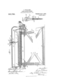
- whiehlligure 1 is a side elevation of my device, parts being broken away to reduce the size of the drawing and to show the interior of the color tank.
- Fig. 2 is an enlarged crosssectional detail, showing the manner of supporting the brush and hangers on the trolley head.
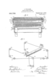
- Fig. 3 is a transverse sectional view taken through lines of Fig. 2 and .looking in the direction of the arrows. it is a perspective vie-w of the brush, showing diagrainmatieally the manner of arranging the guiding belt.
- FIG. 1 designates the table having a horizontal top 2, upon which the paper 2 to be coated is placed. ln order to give the table sufficient stability, it is provided at either side with cross snpports 3 3 and side rails Lll, suitably secured to the table legs 5 5. The bottom rails 5 further add to its stability.
- ay fountain or color tank 7 for the paint or coating fluid, into which the brush end is adapted to he immersed.
- the top of the table at the opposite end is secured a metal strip 3 and bent .inwardly at its top to forni a stop plate against which the paper lies flush while it is being coated.
- rEhe brush 9 is secured to the traveling carriage which is supported above the table and is adapted to travel across the track rails 10-10 which extend along either side of the table. it one end, the rails 10 are bent downwardly7 and secured to the plate 7 which serves also to support the fountain 7. rt their other ends, the rails are supported by standards 11 secured to the table.
- brush carriage proper7 designates a trolley head which extends transversely7 of the tableand has side plates which form depending jaws 13, between which the brush head is clamped by suitable through bolts 14.
- a triangular truck plate 15 To each end of the trolley head is pivotally secured a triangular truck plate 15 by means of the supporting rod 15 extending through space plates 1S" secured in the head 12 seen clearly in ll
- nl lower wheel 17 is journaled upon the stud 1T which is mounted to niove vertically in a slide way (not shown) formed in its respective truck plate 15.
- each stud 1? is provided with a spring 19 secured at one end of the stud and at the other to an extension of the rod 1G. lt will thus be seen tnat the wheels can freely travel upon the track rails but at the saine time the ends of the trolley head are kept in firm bearing with the rails.
- inventioin l provide an endless belt fastened to either end of the brush and trained over a series of belt sheave l/lescribing this ciuistrnetion in detail7 vertieally-disposeil sheaves Q3-23 are ln order that the lower sheaves may be approximately beneath their respective upper sheaves, they are journaled to brackets 2S secured to the legs .5, as seen clearly in Fig. l.
- a paper coating machine the combination with a table, orn a pair of laterally separated track rails, a traveling carriage upon said rails, a coating brush supported by said carriage, a means for maintaining uniformity or movement of the two ends of said carriage comprising parallel rows of guides supported by the table, an endless belt secured to the opposite ends or said travelingl carriage and trained around said guides, said belt being crossed beneath the table by being ⁇ trained around diagonally opposite members of said guides.
- a paper coating machine the combination with a table, of a pair of track rails, a traveling ⁇ carriage upon said rails provided at either end with journal extensions, a coating ⁇ brush pivotally mounted on said carriage and means for maintainingl uniformity ot .movement of the two ends of said carriage., comprising a series of belt sheaves arr; lged partly above and partly below the plane ot the table, and an endless belt trained around said sheaves, crossed helow the table and secured to the respective ends of said carriage.
- a paper coating ⁇ machine in a paper coating ⁇ machine, the com bination with a table, of a pair ot' track rails arranged at opposite sides of the table, a traveling carriage upon said rails, a coating brush secured to said carriage and means maintaining uniformity of movement of the carriage, comprising ⁇ two series of sheaves arranged in vertical parallel planes at the respective sides of the table, a third series arranged in a horizontally-disposed plane below the table, and an endless belt trained around all of said sheaves, crossed below the table by being trained around diagonally opposite members of said sheaves and secured to the respective ends of the carriage.
- a. In a paper coating machine, the combination with a table, of a pair of track rails arranged at opposite sides of the table and bent downwardly at one end, a traveling carriage upon said rails, a coating brush pivotally secured to said carriage, a coating fountain at one end of said table into which said brush is adapted to be immersed, means for maintaining uniformity of movement of the carriage comprising two series or' vertical sheaves arranged in parallel planes at the respective sides of the table, a pair of sheaves rotatably journaled in a plane at right angles to said other sheaves, and an endless belt trained around all of said sheaves crossed below the table by being trained around diagonally opposite members of said sheaves and secured at opposite ends or' said traveling carriage.
- a paper coating machine the com-l bination with a table, of a coating fountain upon one end of said table, a pair oi track rails arranged at opposite sides orp the table and bent downwardly at one end toward said fountain, a traveling carriage upon said rails, a coating brush pivotally secured t0 said carriage, and means maintaining ⁇ uniformity ot' movement of the carriage comprising an endless belt trained around suitable guides and secured at opposite ends of said carriage, said guides being so arranged that the belt descends downward at points adjacent to 'the fountain whereby the brush said table, and means for maintaining unimay be immersed in the latter.
- a paper coating machine the combination with a table, of a coating brush adapted to lit across the upper face of said table, and means for maintaining uniformity of movement of the two ends of said brush comprising parallel rows of guides supported by the table, an endless belt connected to the opposite ends of said brush and trained around said guides, said belt being crossed beneath the table by being trained around diagonally opposite members of said guides.
- a coating brush adapted to move across the upper face of formity of movement of the tivo ends or said brush comprising two series of sheaves arranged in vertical parallel planes at the respective sides of the table above and below the latter, a third series arranged in a. horizontally disposed plane below the table and journaled at right angles to said lirst sheaves, and an endess belt trained around all oi said sheaves, crossed below the table by being trained around diagonally opposite members of said horizontally disposed sheaves, and secured to said brush,
Landscapes
- Coating Apparatus (AREA)
Description
E. WILLIAMS. PAPER GOATING MAGHINE. APPLIOATION FILED Mu s1. 1907.
Patented Apr. 5, 19.1;6. I
2 SHEETS-'SHEET 1.
/L ja/@mmf lAsmNsmN. n C
E. WILLAMS.
PAPER UOATING MACHINE.
APPLICATION HLED MAY 31, 1907.
Patented A111125, 1910.
Z SHEETS-SHEET 2,
Application filed lray 33., 19e?.
To all whom it may concer-a:
Be it known that l, EUGENE lllinrnmis, a citizen of the United States, and a resident of Chicago7 in the county of Coeli and State of illinois, have invented certain new and useful Improvements in laper-Coating Mw chines, of which the following is a specification.
rlhis invention relates to a coating apparatus for coating or painting sheets of paper or analogous material, and in general construction is similar to that set forth in my prior patent, Nlo. 773840.
Among the salient objects of my invention are to provide a construction whereby the pigment or natural coloring` matter may be universally and evenly applied to the paper; to provide a construction which permits the paper to be evenly coated with a minimum and definite number of sweeps of the brush; to provide a construction which prevents binding of the brush wheels upon their respective rails and at the saine time maintains and insures a movement of the brush at right angles with the sides of the table; and in general to provide simple and efficient construction of the character referred to.
The invention will be readily understood from the following description, reference being had to the accompanying drawings in whiehlligure 1 is a side elevation of my device, parts being broken away to reduce the size of the drawing and to show the interior of the color tank. Fig. 2 is an enlarged crosssectional detail, showing the manner of supporting the brush and hangers on the trolley head. Fig. 3 is a transverse sectional view taken through lines of Fig. 2 and .looking in the direction of the arrows. it is a perspective vie-w of the brush, showing diagrainmatieally the manner of arranging the guiding belt.
Referring to the drawingsy 1 designates the table having a horizontal top 2, upon which the paper 2 to be coated is placed. ln order to give the table sufficient stability, it is provided at either side with cross snpports 3 3 and side rails Lll, suitably secured to the table legs 5 5. The bottom rails 5 further add to its stability. it one end of the table is provided ay fountain or color tank 7 for the paint or coating fluid, into which the brush end is adapted to he immersed. @n the top of the table at the opposite end is secured a metal strip 3 and bent .inwardly at its top to forni a stop plate against which the paper lies flush while it is being coated. rEhe brush 9 .is secured to the traveling carriage which is supported above the table and is adapted to travel across the track rails 10-10 which extend along either side of the table. it one end, the rails 10 are bent downwardly7 and secured to the plate 7 which serves also to support the fountain 7. rt their other ends, the rails are supported by standards 11 secured to the table.
llescribing new the. brush carriage proper7 designates a trolley head which extends transversely7 of the tableand has side plates which form depending jaws 13, between which the brush head is clamped by suitable through bolts 14. To each end of the trolley head is pivotally secured a triangular truck plate 15 by means of the supporting rod 15 extending through space plates 1S" secured in the head 12 seen clearly in ll Upon each plate 15 are journaled two upper wheels 16 adapted to ride in the upper sides of tneir respect-ive traer rails. nl lower wheel 17 is journaled upon the stud 1T which is mounted to niove vertically in a slide way (not shown) formed in its respective truck plate 15. ln order to keep the lower wheels in constant bearing with their respective track rails, each stud 1? is provided with a spring 19 secured at one end of the stud and at the other to an extension of the rod 1G. lt will thus be seen tnat the wheels can freely travel upon the track rails but at the saine time the ends of the trolley head are kept in firm bearing with the rails.
t the sides of the coating table, are secured gutters for receiving any drip or overiiow of the coating iiuid during the operation of the apparatus.
Heretolore in a device of this character difliculty has been experienced in preventing binding of the truelr wheels upon the rails and also in securing a traveling of the brush at exact right angles to the sides of the table. To overcome these defects and as an important feature of inf; inventioin l provide an endless belt fastened to either end of the brush and trained over a series of belt sheave l/lescribing this ciuistrnetion in detail7 vertieally-disposeil sheaves Q3-23 are ln order that the lower sheaves may be approximately beneath their respective upper sheaves, they are journaled to brackets 2S secured to the legs .5, as seen clearly in Fig. l. ln a horizontal plane approximately coincident with the lower peripheries of the sets of lower sheaves and at right angles thereto, are journaled, on brackets 32, four sheaves Q-30 and 31-31, two at each side of the table, as seen clearly in Fig. il. The outer part of the periphery of each of the horizontal sheaves coincides with the lower part oit the periphery of each ot their respective vertical sheaves.
lescribing` now the manner in which the endless belt is trained over the sheaves and starting for example with pulley 23, the belt is trained from the latter over sheaves 2l and 2G to horizontal sheave 31, thence across to sheave 30, and around sheaves 25 and to sheaves 24, thence downwardly to sheave 2G over sheave 31 across to sheave 30 and up over sheave Q5 back to sheave 23. r'he upper laps of the belt are integrally connected to the truck plates 15 by suitable eyes 553-33 which are so arranged that the eyes may easily ride by the upper sheaves 23-23 when the brush is being immersed in the liquid. From the arrangement of the belt described it will be seen that as the brush moves across the paper it will at all times be at exact right angles to the sides o1L the table but will have oscillatory movement inasmuch as the truck plates l5 are pivotally connected to the trolley head 1Q. frs hereinbefore stated this arrangement of the belt also prevents binding of the 7heels upon thei respective rails.
lllhile l have shown and described a preferred embodiment ot the invention, yet it will be understood that the details may be somewhat modified without departing from the spirit of the invention;
l claim as my invention:
1. ln a paper coating machine, the combination with a table, orn a pair of laterally separated track rails, a traveling carriage upon said rails, a coating brush supported by said carriage, a means for maintaining uniformity or movement of the two ends of said carriage comprising parallel rows of guides supported by the table, an endless belt secured to the opposite ends or said travelingl carriage and trained around said guides, said belt being crossed beneath the table by being` trained around diagonally opposite members of said guides.
ln a paper coating machine, the combination with a table, of a pair of track rails, a traveling` carriage upon said rails provided at either end with journal extensions, a coating` brush pivotally mounted on said carriage and means for maintainingl uniformity ot .movement of the two ends of said carriage., comprising a series of belt sheaves arr; lged partly above and partly below the plane ot the table, and an endless belt trained around said sheaves, crossed helow the table and secured to the respective ends of said carriage.
3. in a paper coating` machine, the com bination with a table, of a pair ot' track rails arranged at opposite sides of the table, a traveling carriage upon said rails, a coating brush secured to said carriage and means maintaining uniformity of movement of the carriage, comprising` two series of sheaves arranged in vertical parallel planes at the respective sides of the table, a third series arranged in a horizontally-disposed plane below the table, and an endless belt trained around all of said sheaves, crossed below the table by being trained around diagonally opposite members of said sheaves and secured to the respective ends of the carriage.
a. In a paper coating machine, the combination with a table, of a pair of track rails arranged at opposite sides of the table and bent downwardly at one end, a traveling carriage upon said rails, a coating brush pivotally secured to said carriage, a coating fountain at one end of said table into which said brush is adapted to be immersed, means for maintaining uniformity of movement of the carriage comprising two series or' vertical sheaves arranged in parallel planes at the respective sides of the table, a pair of sheaves rotatably journaled in a plane at right angles to said other sheaves, and an endless belt trained around all of said sheaves crossed below the table by being trained around diagonally opposite members of said sheaves and secured at opposite ends or' said traveling carriage.
5. ln a paper coating machine, the com-l bination with a table, of a coating fountain upon one end of said table, a pair oi track rails arranged at opposite sides orp the table and bent downwardly at one end toward said fountain, a traveling carriage upon said rails, a coating brush pivotally secured t0 said carriage, and means maintaining` uniformity ot' movement of the carriage comprising an endless belt trained around suitable guides and secured at opposite ends of said carriage, said guides being so arranged that the belt descends downward at points adjacent to 'the fountain whereby the brush said table, and means for maintaining unimay be immersed in the latter.
6. ln a paper coating machine, the combination with a table, of a coating brush adapted to lit across the upper face of said table, and means for maintaining uniformity of movement of the two ends of said brush comprising parallel rows of guides supported by the table, an endless belt connected to the opposite ends of said brush and trained around said guides, said belt being crossed beneath the table by being trained around diagonally opposite members of said guides.
7. In a paper coating machine, the combination With a table, of a coating brush adapted to move across the upper face of formity of movement of the tivo ends or said brush comprising two series of sheaves arranged in vertical parallel planes at the respective sides of the table above and below the latter, a third series arranged in a. horizontally disposed plane below the table and journaled at right angles to said lirst sheaves, and an endess belt trained around all oi said sheaves, crossed below the table by being trained around diagonally opposite members of said horizontally disposed sheaves, and secured to said brush,
EUGENE YVI'LLIAB/IS. litnesses FRANK G. Eliminar, EMILIE Rosa.
Priority Applications (1)
| Application Number | Priority Date | Filing Date | Title |
|---|---|---|---|
| US37648207A US953728A (en) | 1907-05-31 | 1907-05-31 | Paper-coating machine. |
Applications Claiming Priority (1)
| Application Number | Priority Date | Filing Date | Title |
|---|---|---|---|
| US37648207A US953728A (en) | 1907-05-31 | 1907-05-31 | Paper-coating machine. |
Publications (1)
| Publication Number | Publication Date |
|---|---|
| US953728A true US953728A (en) | 1910-04-05 |
Family
ID=3022135
Family Applications (1)
| Application Number | Title | Priority Date | Filing Date |
|---|---|---|---|
| US37648207A Expired - Lifetime US953728A (en) | 1907-05-31 | 1907-05-31 | Paper-coating machine. |
Country Status (1)
| Country | Link |
|---|---|
| US (1) | US953728A (en) |
-
1907
- 1907-05-31 US US37648207A patent/US953728A/en not_active Expired - Lifetime
Similar Documents
| Publication | Publication Date | Title |
|---|---|---|
| US1879513A (en) | Plate glass transporting truck | |
| US2211082A (en) | Slide stand for cloth cutting machines and the like | |
| US3533118A (en) | Loading bridge | |
| US710561A (en) | Type-writing-machine support. | |
| US1524705A (en) | Cloth-laying machine | |
| US689563A (en) | Dip painting apparatus. | |
| US1852488A (en) | Aligning and supporting means for loading apparatus pans | |
| US622513A (en) | Apparatus for manufacturing mirrors | |
| US375319A (en) | ferausson | |
| DE433686C (en) | Device for testing suspension springs and spring groups | |
| DE363153C (en) | Photographic drying rack | |
| US249762A (en) | hayerstigk | |
| US284684A (en) | Apparatus for painting fence-pickets by dipping | |
| US671588A (en) | Pickling-machine for sheet metal. | |
| US957525A (en) | Cloth-piling machine. | |
| US1025671A (en) | Holder for liquid-coating machines. | |
| US1006987A (en) | Hand printing-machine. | |
| US629267A (en) | Device for hanging tobacco. | |
| US846123A (en) | Paper-folding machine. | |
| US765278A (en) | Suspended wheel-jack. | |
| US545753A (en) | Starch ing-machine | |
| US856641A (en) | Fountain glue-brush. | |
| DE1029542B (en) | Device for covering the edges of glass parts | |
| US235002A (en) | Herman miller | |
| US763682A (en) | Machine for forming rubber articles. |