US953726A - Car-fender. - Google Patents
Car-fender. Download PDFInfo
- Publication number
- US953726A US953726A US51862009A US1909518620A US953726A US 953726 A US953726 A US 953726A US 51862009 A US51862009 A US 51862009A US 1909518620 A US1909518620 A US 1909518620A US 953726 A US953726 A US 953726A
- Authority
- US
- United States
- Prior art keywords
- fender
- arms
- car
- arm
- bolt
- Prior art date
- Legal status (The legal status is an assumption and is not a legal conclusion. Google has not performed a legal analysis and makes no representation as to the accuracy of the status listed.)
- Expired - Lifetime
Links
- 238000010276 construction Methods 0.000 description 2
- 230000002708 enhancing effect Effects 0.000 description 1
- 238000003780 insertion Methods 0.000 description 1
- 230000037431 insertion Effects 0.000 description 1
- 238000004519 manufacturing process Methods 0.000 description 1
- 239000000463 material Substances 0.000 description 1
- 239000002184 metal Substances 0.000 description 1
- 238000000034 method Methods 0.000 description 1
- 230000003534 oscillatory effect Effects 0.000 description 1
- 230000000284 resting effect Effects 0.000 description 1
- 238000005096 rolling process Methods 0.000 description 1
Images
Classifications
-
- B—PERFORMING OPERATIONS; TRANSPORTING
- B60—VEHICLES IN GENERAL
- B60R—VEHICLES, VEHICLE FITTINGS, OR VEHICLE PARTS, NOT OTHERWISE PROVIDED FOR
- B60R21/00—Arrangements or fittings on vehicles for protecting or preventing injuries to occupants or pedestrians in case of accidents or other traffic risks
- B60R21/34—Protecting non-occupants of a vehicle, e.g. pedestrians
Definitions
- My invention relates to car fenders, and has for its object the provision of a simple, improved and highly etlicient apparatus of this class, which is inexpensive of manufacture, easy of operation, and light, strong and durable in its construction, thus enhancing the practicability and commercial value thereof.
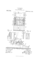
- Figure l. is a plan view of my fender in operative association with a car.
- Fig. 2 is a side view thereof, and Figs. 3 and at are details of the hanger bracket for the fender.
- 1 designates the front end portion of a car to the bottom of which adjacent each side thereof are secured the pendent brackets 2, which are shown as constituting U-shaped loops, the le terminals of which are bent outwardly to form feet through which securing bolts or screws pass.
- the vertical portions of the bracket legs are provided near their front and rear edges with series of bolt holes 3 which register with those of the opposite leg for the purpose hereinafter described.
- each bracket 2 Projecting rearwardly through each bracket 2 is a bearing arm 4., which is held in properly adjusted position in the bracket by resting on a bolt passing through the proper ones of the forward sets of holes 3 and bearing upwardly against a bolt 6 passing through the proper ones of the rear sets of holes 3, as indicated in Fig. 2, thus holding the forward end of the arm sup- Specification of Letters Patent.
- Each arm 4 is provided on its lower edge with a series of spaced notches 7 for receiving the lower bolt at whatever position of longitudinal adjustment it is desired to place an arm relative to its carrying bracket.
- each arm Projecting forwaii'dly from each arm at to which its rear end is pivotally attached, as at 8, is a second arm 9, which is provided at its rear end beneath the plane of its pivot with asegmental slot- 10 through which a bolt 11 adjust-ably projects, said bolt being adapted to coact with the lower edge of the arm -11: to serve as a stop for limiting the lowering of the forward end of the arm 9.
- each arm 9 is angled upwardly and provided at its terminal with a bearing 12, which is prefer; bly circular in form and provided with an opening 13 at its upper side.
- the forward ends of the arms 5) are also preferably forked or verti cally slotted longitudinally thereof as indicated in Fig. 1.
- 1 1 designates the main fender of the device, which is longitudinally curved as is customary and comprises a plurality of longitudinally extending fender bars 15, which have their ends pierced by forward and rear transverse shafts or rods 16, 16 and spaced apart by sleeves 17 on said rods, but may be of any other suitable construction, if desired.
- the fender let has two of the outer ones of its bars projecting through the forked ends of the arms 9 and pivotedto the furcations thereof as at 18'.
- the rear end of the fender 14L is weighted in any suitable manner as by enlarging the sleeves 17 at such end and making the same of a heavy material, and the pivots 18 are disposed sufficiently forward to adapt such weighted end to serve as a counterpoise for normally maintaining the forward end of the fender elevated a suitable distance above the rails 19 of a track.
- the fender-bars through which the pivots 18 project are provided with a series of pivot holes 20 to permit an adjustment of the fender pivots as it may be desired to increase or decrease the power of the weighted end. of the fender, as is apparent.
- the fender 22 designates a guard fender, which is provided adjacent its lower edge with a set of bearing hooks 2", adapted for fitting into the bearings 12 at the ends of the arms 9.
- the hooks 28 are preferably otl' set rearwardly from the face of the fender 22 and fashioned to permit their insertion into or removal from the bearings 12 when the fender 22 is in one position only of its pivotal movement.
- the fender may be fern ed of strap-metal, as indicated, or in any other suitable manner, and has its upper end curving rearwardly over the rear end of the fender and extending to adjacent the car body, as shown.
- the pivot 18 is so adjusted relative to the main fender 14: that the weight of the rear end of the fender will be sulficient to maintain the fender nose elevated, say four or five inches, above the track. Should any object which is of sutlicient weight to overcome the weight 1' of the rear end of the fender, strike the forward endof the same, such end would instantly lower to prevent the object from rolling under the fender. lVhen the fender has been relieved of the weight of such object the weighted rear end of the same will immediately act to raise the forward end of the fender to its normal position.
- the apparatus can be easily and quickly disconthe motor-man to lower the fender to nected from or attached to a car; that there 3 are few parts to get out of order, and that it 5 is not necessary to remove the fender to couple up to any other car, as the case Q with many of the fenders now on the marl ket, but simply to turn the guard fender 22 arrangei'nent of the parts, except in so far as such limitations are specified in the claims.
- the combination with fender-supporting arms. of a fender adjustably pivoted to the arms and adapted to normally stand in one position. and means cooperating with the arms to limit the pivotal movements of the fender.
Landscapes
- Engineering & Computer Science (AREA)
- Mechanical Engineering (AREA)
- Body Structure For Vehicles (AREA)
Description
J. WEAVER. GAR FENDER. APPLICATION FILED SEPT. 20, 1909.
Patented Apr. 5, 1916.
TAX/7x7 11 JOHN \V. \FKIEAVFR, OF TOLEDO, OHIO.
CAR- FENDER.
To all whom it may concern:
Be it known that l, JOHN lV. WEAVER, a citizen of the United States, and a resident of Toledo, in the county of Lu *as and State of Ohio, have invented a certain new and useful Car-Fender; and I do hereby declare the following to be a full, clear, and exact description of the invention, such as will enable others skilled .in the art to which it appertains to make and use the same, reference being had to the accompanying drawings, and to the figures of reference marked thereon, which form a part of this specification.
My invention relates to car fenders, and has for its object the provision of a simple, improved and highly etlicient apparatus of this class, which is inexpensive of manufacture, easy of operation, and light, strong and durable in its construction, thus enhancing the practicability and commercial value thereof.
Further objects of my invention as well as the operation, COIlStl'LlCt-iOll and arrangement of the parts thereof will be fully described in the following specification, and a preferred cmbmliment of the same is illustrated in the accompanying drawings, in which,
Figure l. is a plan view of my fender in operative association with a car. Fig. 2 is a side view thereof, and Figs. 3 and at are details of the hanger bracket for the fender.
Referring to the drawings, 1 designates the front end portion of a car to the bottom of which adjacent each side thereof are secured the pendent brackets 2, which are shown as constituting U-shaped loops, the le terminals of which are bent outwardly to form feet through which securing bolts or screws pass. The vertical portions of the bracket legs are provided near their front and rear edges with series of bolt holes 3 which register with those of the opposite leg for the purpose hereinafter described.
Projecting rearwardly through each bracket 2 is a bearing arm 4., which is held in properly adjusted position in the bracket by resting on a bolt passing through the proper ones of the forward sets of holes 3 and bearing upwardly against a bolt 6 passing through the proper ones of the rear sets of holes 3, as indicated in Fig. 2, thus holding the forward end of the arm sup- Specification of Letters Patent.
Application filed September 20, 1909.
fcatented Apr. 5, 1910.
Serial No. 518,620.
ported at the desired elevation. Each arm 4 is provided on its lower edge with a series of spaced notches 7 for receiving the lower bolt at whatever position of longitudinal adjustment it is desired to place an arm relative to its carrying bracket. To remove the arms a from the brackets it is only neces sary to raise the forward ends of the same sufficient to disengage a notch T from the bolt and then to draw the arms forward from the brackets on a slight incline.
Projecting forwaii'dly from each arm at to which its rear end is pivotally attached, as at 8, is a second arm 9, which is provided at its rear end beneath the plane of its pivot with asegmental slot- 10 through which a bolt 11 adjust-ably projects, said bolt being adapted to coact with the lower edge of the arm -11: to serve as a stop for limiting the lowering of the forward end of the arm 9.
The forward end of each arm 9 is angled upwardly and provided at its terminal with a bearing 12, which is prefer; bly circular in form and provided with an opening 13 at its upper side. The forward ends of the arms 5) are also preferably forked or verti cally slotted longitudinally thereof as indicated in Fig. 1.
1 1 designates the main fender of the device, which is longitudinally curved as is customary and comprises a plurality of longitudinally extending fender bars 15, which have their ends pierced by forward and rear transverse shafts or rods 16, 16 and spaced apart by sleeves 17 on said rods, but may be of any other suitable construction, if desired. The fender let has two of the outer ones of its bars projecting through the forked ends of the arms 9 and pivotedto the furcations thereof as at 18'. The rear end of the fender 14L is weighted in any suitable manner as by enlarging the sleeves 17 at such end and making the same of a heavy material, and the pivots 18 are disposed sufficiently forward to adapt such weighted end to serve as a counterpoise for normally maintaining the forward end of the fender elevated a suitable distance above the rails 19 of a track. The fender-bars through which the pivots 18 project are provided with a series of pivot holes 20 to permit an adjustment of the fender pivots as it may be desired to increase or decrease the power of the weighted end. of the fender, as is apparent.
The lowering movement of the rear end of the fender is limited by the sleeves 17 striking against the arms 9, and the raising thereof relative to such arms is limited by el-evises 21, which are carried by the pivotbars 15 to the rear of their pivots and loop under such arms, asshown.
22 designates a guard fender, which is provided adjacent its lower edge with a set of bearing hooks 2", adapted for fitting into the bearings 12 at the ends of the arms 9. The hooks 28 are preferably otl' set rearwardly from the face of the fender 22 and fashioned to permit their insertion into or removal from the bearings 12 when the fender 22 is in one position only of its pivotal movement. The fender may be fern ed of strap-metal, as indicated, or in any other suitable manner, and has its upper end curving rearwardly over the rear end of the fender and extending to adjacent the car body, as shown.
In the use of my improved fender, the pivot 18 is so adjusted relative to the main fender 14: that the weight of the rear end of the fender will be sulficient to maintain the fender nose elevated, say four or five inches, above the track. Should any object which is of sutlicient weight to overcome the weight 1' of the rear end of the fender, strike the forward endof the same, such end would instantly lower to prevent the object from rolling under the fender. lVhen the fender has been relieved of the weight of such object the weighted rear end of the same will immediately act to raise the forward end of the fender to its normal position.
I l l l l Should it be desired to fold the fender up against the end of the car for any reason, the same may f be easily accomplished by first turmng the fender forwardly upon the main fender l 1 1 and then folding the two fenders and the arms 9 up against. the car on the pivots 8 of such arms.
l l v I It is thus ap aarent that I have provided a fender which automatically lowers to pick up an article or ob ect on the track with whiclrit may come in contact, thereby obviating the dangerous method of dependmgj upon catch an ob ect. it is also apparent that the apparatus can be easily and quickly disconthe motor-man to lower the fender to nected from or attached to a car; that there 3 are few parts to get out of order, and that it 5 is not necessary to remove the fender to couple up to any other car, as the case Q with many of the fenders now on the marl ket, but simply to turn the guard fender 22 arrangei'nent of the parts, except in so far as such limitations are specified in the claims.
Having thus described my invention what I claim as new and desire to secure by Letters Patent, is,
1. In an apparatus of the class described, the combination with" fender-supporting arms, of a fender pivotally carried thereby and being influenced to normally stand in one position, said arms limiting the movements of the fender in one direction, and means cooperating with said arms to limit the movements of the tender in the other direction.
2. In an apparatus of the class described, the combination with fender-supporting arms. of a fender adjustably pivoted to the arms and adapted to normally stand in one position. and means cooperating with the arms to limit the pivotal movements of the fender.
3. In an apparatus of the class described the combination with fender supporting arms, of a fender pivotally carried by such arms and vieldingly held in one position. and a clevis member carried by the fender and cooperating with one of such arms to limit the oscillatory movements of the fender relative to said arms.
at. In an apparatus of the class described, the combination of pivoted fender supporting arms having their free ends angled upwardly, a main fender pivotally carried by such arms, and a guard fender pivotally supported by the angled ends of the arms and superposing the rear portion of the main fender.
5. in an apparatus of the class described. the combination of pivoted fender supporting arms having their free ends angled, a main fender pivot-ally carried by such arms, and a guard fender pivotally and removably carried by the angled ends of such arms.
signed my name to this specification in the presence of two subscribing witnesses.
JOHN 1V. WEAVER. Witnesses C. W. OWEN,
CORNELL SCH REIBER.
Priority Applications (1)
| Application Number | Priority Date | Filing Date | Title |
|---|---|---|---|
| US51862009A US953726A (en) | 1909-09-20 | 1909-09-20 | Car-fender. |
Applications Claiming Priority (1)
| Application Number | Priority Date | Filing Date | Title |
|---|---|---|---|
| US51862009A US953726A (en) | 1909-09-20 | 1909-09-20 | Car-fender. |
Publications (1)
| Publication Number | Publication Date |
|---|---|
| US953726A true US953726A (en) | 1910-04-05 |
Family
ID=3022133
Family Applications (1)
| Application Number | Title | Priority Date | Filing Date |
|---|---|---|---|
| US51862009A Expired - Lifetime US953726A (en) | 1909-09-20 | 1909-09-20 | Car-fender. |
Country Status (1)
| Country | Link |
|---|---|
| US (1) | US953726A (en) |
-
1909
- 1909-09-20 US US51862009A patent/US953726A/en not_active Expired - Lifetime
Similar Documents
| Publication | Publication Date | Title |
|---|---|---|
| US1019811A (en) | Flanger for railways. | |
| US786519A (en) | Pouch-transferring means. | |
| US547166A (en) | Car-fender | |
| US552655A (en) | Car-fender | |
| US956483A (en) | Car-fender. | |
| US930970A (en) | Automatic car-fender. | |
| US538982A (en) | Oar fender | |
| US757845A (en) | Car-fender. | |
| US1170307A (en) | Fender for automobiles, &c. | |
| US871521A (en) | Car-fender. | |
| US906047A (en) | Self-acting fender. | |
| US552286A (en) | Street-car fender | |
| US621476A (en) | Car-fender | |
| US985541A (en) | Life-guard for railway-cars. | |
| US1010367A (en) | Street-car fender. | |
| US610779A (en) | William thomas watson | |
| US580119A (en) | Island | |
| US599470A (en) | Car-fender | |
| US547218A (en) | Andrew b | |
| US544692A (en) | John f | |
| US583017A (en) | Car-fender | |
| US585729A (en) | Car-fender | |
| US557334A (en) | holler | |
| US560270A (en) | Joseph i-i | |
| US650491A (en) | Car-fender. |