US9536388B2 - Gaming chip having capacitive coupling and related methods - Google Patents
Gaming chip having capacitive coupling and related methods Download PDFInfo
- Publication number
- US9536388B2 US9536388B2 US14/499,018 US201414499018A US9536388B2 US 9536388 B2 US9536388 B2 US 9536388B2 US 201414499018 A US201414499018 A US 201414499018A US 9536388 B2 US9536388 B2 US 9536388B2
- Authority
- US
- United States
- Prior art keywords
- gaming
- chip
- token
- tokens
- transceiver
- Prior art date
- Legal status (The legal status is an assumption and is not a legal conclusion. Google has not performed a legal analysis and makes no representation as to the accuracy of the status listed.)
- Expired - Fee Related, expires
Links
Images


Classifications
-
- G—PHYSICS
- G07—CHECKING-DEVICES
- G07F—COIN-FREED OR LIKE APPARATUS
- G07F17/00—Coin-freed apparatus for hiring articles; Coin-freed facilities or services
- G07F17/32—Coin-freed apparatus for hiring articles; Coin-freed facilities or services for games, toys, sports, or amusements
- G07F17/3244—Payment aspects of a gaming system, e.g. payment schemes, setting payout ratio, bonus or consolation prizes
- G07F17/3248—Payment aspects of a gaming system, e.g. payment schemes, setting payout ratio, bonus or consolation prizes involving non-monetary media of fixed value, e.g. casino chips of fixed value
-
- G—PHYSICS
- G06—COMPUTING OR CALCULATING; COUNTING
- G06K—GRAPHICAL DATA READING; PRESENTATION OF DATA; RECORD CARRIERS; HANDLING RECORD CARRIERS
- G06K19/00—Record carriers for use with machines and with at least a part designed to carry digital markings
- G06K19/04—Record carriers for use with machines and with at least a part designed to carry digital markings characterised by the shape
- G06K19/041—Constructional details
- G06K19/047—Constructional details the record carrier being shaped as a coin or a gambling token
-
- G—PHYSICS
- G07—CHECKING-DEVICES
- G07F—COIN-FREED OR LIKE APPARATUS
- G07F17/00—Coin-freed apparatus for hiring articles; Coin-freed facilities or services
- G07F17/32—Coin-freed apparatus for hiring articles; Coin-freed facilities or services for games, toys, sports, or amusements
-
- G—PHYSICS
- G07—CHECKING-DEVICES
- G07F—COIN-FREED OR LIKE APPARATUS
- G07F17/00—Coin-freed apparatus for hiring articles; Coin-freed facilities or services
- G07F17/32—Coin-freed apparatus for hiring articles; Coin-freed facilities or services for games, toys, sports, or amusements
- G07F17/3202—Hardware aspects of a gaming system, e.g. components, construction, architecture thereof
- G07F17/3216—Construction aspects of a gaming system, e.g. housing, seats, ergonomic aspects
- G07F17/322—Casino tables, e.g. tables having integrated screens, chip detection means
-
- G—PHYSICS
- G07—CHECKING-DEVICES
- G07F—COIN-FREED OR LIKE APPARATUS
- G07F17/00—Coin-freed apparatus for hiring articles; Coin-freed facilities or services
- G07F17/32—Coin-freed apparatus for hiring articles; Coin-freed facilities or services for games, toys, sports, or amusements
- G07F17/3241—Security aspects of a gaming system, e.g. detecting cheating, device integrity, surveillance
-
- G—PHYSICS
- G07—CHECKING-DEVICES
- G07F—COIN-FREED OR LIKE APPARATUS
- G07F17/00—Coin-freed apparatus for hiring articles; Coin-freed facilities or services
- G07F17/32—Coin-freed apparatus for hiring articles; Coin-freed facilities or services for games, toys, sports, or amusements
- G07F17/3244—Payment aspects of a gaming system, e.g. payment schemes, setting payout ratio, bonus or consolation prizes
- G07F17/3251—Payment aspects of a gaming system, e.g. payment schemes, setting payout ratio, bonus or consolation prizes involving media of variable value, e.g. programmable cards, programmable tokens
Definitions
- This disclosure relates to systems and methods which can determine at least the denomination of a token resting on a surface and, more specifically, systems and methods which can determine properties of a gaming token resting on a gaming table.
- Gaming tokens are well known. Tokens are used in gaming in lieu of cash and usually represent different token denominations. Typically, tokens appear as molded plastic cylindrical discs (or plastic cylindrical discs) with metallic cores or are rectangular tiles and have different color combinations to distinguish denomination value.
- the disc shaped tokens are often referred to as chips or checks. In many casinos, these chips are of solid colors but in others establishments, these chips are of different basic colors and have radial bands of a distinguishing color which can be seen when viewing the circular face of the chip as well as when viewing the perimeter of the chip. Thus, when the chips are stacked on a playing table surface or in a chip tray, the different denominations of the chips can be visually distinguished. Distinguishing between the denominations of the chips is important since each chip represents its stated value and can be exchanged for currency. In casinos in the United States, these chips typically have distinguishing colors representing at least the following denominations: $1, $5, $25, $100, and $500.
- a drawback to using such molded tokens is that manual counting is required, which can introduce a human error element into the count. Routinely, floor personnel walk to each gaming table to count the chips in the chip trays. They must, through observation of the number of stacks of a known number of chips of the same denomination, make this determination without significantly interrupting play. It would be useful to obtain accurate chip counts without relying upon the expertise of floor personnel to assemble and count the chip stacks.
- the chip amounts in circulation were able to be accurately determined. By determining how many chip are on hand and how many chip are in play, the number of the chips that have been lost or kept by players as souvenirs may be calculated.
- the system includes: a plurality of gaming tokens; a playing surface including a network of conductors disposed to make electrical contact with the conductive rims of the gaming tokens; one or more transceivers disposed under the playing surface and associated with areas where the gaming tokens are placed on the playing surface; and an identification processor in communication with the transceiver to determine the denomination of the token from the data.
- Each transceiver is configured to transmit an electromagnetic interrogation signal to the conductive layer of a gaming token resting on the playing surface.
- the grounded circuit in response to the interrogation signal, responds with data to identify the chip denomination through capacitive coupling between the conductive layer and a transceiver.
- each electronic gaming token includes: a substrate having a first face, a second face, and a perimeter; a circuit including a power source, token processor, and token memory disposed in the substrate, the memory configured to store data that identifies at least a denomination of the gaming token; first and second conductive layers disposed on the first and second faces respectively, and a conductive rim at the perimeter.
- a method for tracking gaming tokens used by a player for the play of a game having a playing surface includes: providing a set of gaming tokens each including, (i) a substrate having a first face, a second face, and a perimeter; (ii) a circuit including a power source, a token processor, and a token memory disposed in the substrate, the memory configured to store data that identifies at least a denomination of the gaming token, (iii) first and second conductive layers disposed on the first and second faces, respectively, and (iv) a conductive rim at the perimeter; configuring the playing surface to include conductors that create a capacitive coupling with a token face conductive layer resting on the playing surface; and equipping the playing surface with a transceiver for issuing an interrogation signal to the playing surface conductors, the interrogation signal passing through capacitive coupling to the token face conductive layer resting on the playing surface and the token processor, the processor responding with a data
- the disclosed embodiments further relates to machine readable media on which are stored embodiments of the disclosed invention described in herein. It is contemplated that any media suitable for retrieving instructions is within the scope of the disclosed embodiments. By way of example, such media may take the form of magnetic, optical, or semiconductor media.
- the invention also relates to data structures that contain embodiments of the disclosed invention, and to the transmission of data structures containing embodiments of the disclosed invention.
- FIG. 1A illustrates a top view of the basic components of the E-Chip.
- FIG. 1B illustrates a cross-sectional side view of the basic components of the E-Chip.
- FIG. 2 illustrates a Parallel Plate Capacitor
- FIG. 3 illustrates a Capacitive Coupling in E-chip.
- FIG. 4 illustrates E-Chip circuitry
- FIG. 5 illustrates the Communication between E-chips.
- FIG. 6A illustrates a top view of the E-Chip.
- FIG. 6B illustrates a cross-sectional side view of the E-Chip.
- FIG. 7A illustrates a bottom view of an E-Chip Fabrication: Layer-1.
- FIG. 7B illustrates a top view of an E-Chip Fabrication: Layer-1.
- FIG. 8A illustrates a bottom view of an E-Chip Fabrication: Layer-2 and Layer-3.
- FIG. 8B illustrates a top view of an E-Chip Fabrication: Layer-2 and Layer-3.
- FIG. 9A illustrates a bottom view of an E-Chip Fabrication: Layer-4.
- FIG. 9B illustrates a top view of an E-Chip Fabrication: Layer-4.
- FIG. 10 illustrates an E-Chip Fabrication and thickness of each layer.
- FIG. 11 illustrates a longitudinal view of the table cloth.
- FIG. 12 illustrates a top view of the table cloth.
- FIG. 13 illustrates a side view of the table cloth with the Transparent Conductive Polymer.
- FIG. 14 illustrates a side view of the table cloth with the Transparent Conductive Polymer, as well as the Table E-Chip Transceiver.
- FIG. 15 illustrates a perspective view of the table cloth with a first player area and a second player area of the conductive polymer layer grid.
- FIG. 16 illustrates a side view of the table cloth with the Transparent Conductive Polymer, as well as the Table E-Chip Transceiver and Central Table System.
- FIG. 17 illustrates a layout view of the E-Chip stack, the tables, the table area transceiver, the table system, the Central Chip tracking system, and the casino floor.
- FIG. 18 illustrates a side view of two squarely stacked E-Chips; E-Chip 1 and E-Chip 2.
- FIG. 19 illustrates a circuit diagram of E-Chip 1 and E-Chip 2, as shown in FIG. 18 .
- FIG. 20 illustrates a side view of two off-center stacked E-Chips; E-Chip 1 and E-Chip 2.
- FIG. 21 illustrates a circuit diagram of E-Chip 1 and E-Chip 2, as shown in FIG. 20 .
- FIG. 22 illustrates a side view of two partially stacked E-Chips; E-Chip 1 and E-Chip 2.
- FIG. 23 illustrates a circuit diagram of E-Chip 1 and E-Chip 2, as shown in FIG. 22 .
- FIG. 24 illustrates a stack of chips, T-1 to T-N, placed on the table cloth, as well as the table E-Chip Transceiver, the table system, and the Central Chip Tracking System.
- FIG. 25 illustrates a stack of chips being moved from a Dealer area to a first player area on the table cloth, which is mapped to a Baccarat table.
- FIG. 26 illustrates a stack of chips being moved from a first player area to a player betting area on the table cloth, which is mapped to a Baccarat table.
- FIG. 27A illustrates a top view of a two light sensor that is embedded into an E-Chip with a slit on top surface of the both sides of the E-Chip covered with small glass for light.
- FIG. 27B illustrates a longitudinal view of a two light sensor that is embedded into an E-Chip with a slit on top surface of the both sides of the E-Chip covered with small glass for light.
- FIG. 28 illustrates longitudinal view of a bad E-Chip.
- FIG. 29 illustrates an E-Chip with a small aberration introduced to ensure that the inner ring gets shorted to the outer ground ring when stacked E-Chips overlap perfectly.
- FIG. 30 illustrates a perspective view of a gaming machine in accordance with one or more embodiments.
- FIG. 31A illustrates a block diagram of the physical and logical components of the gaming machine of FIG. 1 in accordance with one or more embodiments.
- FIG. 31B illustrates a block diagram of the physical and logical components of the gaming machine of FIG. 1 in accordance with one or more embodiments.
- FIG. 32 illustrates a block diagram of the logical components of a gaming kernel in accordance with one or more embodiments.
- FIG. 33A illustrates a schematic block diagram showing the hardware elements of a networked gaming system in accordance with one or more embodiments.
- FIG. 33B illustrates a schematic block diagram showing the hardware elements of a networked gaming system in accordance with one or more embodiments.
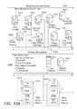
- FIG. 34 illustrates a diagram showing an example of architecture for tying a casino enterprise network to an external provider of games and content to Internet or broadband communication capable devices.
- the present application also relates to an apparatus for performing the operations herein.
- This apparatus may be specially constructed for the required purposes, or it may comprise a general purpose computer selectively activated or reconfigured by a computer program stored in the computer.
- a computer program may be stored in a computer readable storage medium, such as, but not limited to, any type of disk, including floppy disks, optical disks, CD-ROMs, and magnetic-optical disks, read-only memories (ROMs), random access memories (RAMs), EPROMs, EEPROMs, magnetic or optical cards, or any type of media suitable for storing electronic instructions, and each coupled to a computer system bus.
- FIGS. 1A-29 illustrate various embodiments of the disclosed systems and methods which can determine at least the denomination of a token (e.g., electronic chip or E-chip) resting on a surface using capacitive coupling. Also disclosed are systems and methods for systems and methods that may determine additional properties of an E-chip resting on a surface of a gaming table using capacitive coupling.
- a token e.g., electronic chip or E-chip
- an RFID chip contains an RFID tag embedded inside the chip.
- the RFID tag usually contains the ID of the chip and may include other pertinent data.
- passive RFID tags containing a radio device that broadcast the serial number when brought close to a RFID reader.
- the E-chip capacitive coupling system and method communicates to the reader using capacitive coupling to enable peer-to-peer communication between E-chips and to the gaming table.
- the E-chip capacitive coupling system and method enables the use of E-Chips that have IDs, follow definite communication protocol, and implement physical design that are very difficult to duplicated.
- E-Chips are associated with a particular player or players.
- the E-chip capacitive coupling system and method greatly enhances inventory management of the E-Chips.
- the E-chip capacitive coupling system and method may increase the game speed, since chips do not need to be manual counted, which can be a time consuming and cumbersome process.
- the E-chip capacitive coupling system and method can detect various kinds of fraud from players.
- the components of the E-Chip system include: (1) the E-Chips themselves, which contain internal electronic circuitry; (2) the clothing on the gaming table (e.g., a layered clothing is using with the E-Chip system); (3) a transceiver at the bottom of the table which communicates with the chip stack; a table system that receives information from the transceivers; (4) a central chip tracking and inventory system; and (5) integrated with peripheral systems such as sorters, dispensers, faulty chip detectors etc.
- the basic components of the E-Chip include an embedded microcontroller with data and program memory, as well as a lightweight ultra-thin battery that supplies power to the microcontroller.
- the top and bottom portions of the chip include: (1) a flat circular conductive layers made of copper or any other conductive material, (2) a flat circular insulating layer on top of the conductive layer, and (3) a flat ring shaped conductive layer that runs around the periphery of the chip.
- the embedded microcontroller may be an 8-bit microcontroller, such as ATMEL's ATtiny85.
- This microcontroller has the following components: (1) an 8K Bytes of In-System programmable flash memory which can contain program and constant data (which are used for storing program memory, casino specific data, and chip specific data, which are typically one time programmed or re-programmed in a secure manner), and (2) a 512 Bytes of Internal RAM (which are used for storing Player ID).
- the E-Chip is programmed with casino related information such as a Casino ID, Casino Code, and Secret Encryption code. This information may be one-time programmable or optionally re-programmable in a secure manner.
- the E-Chip is programmed with chip related information such as Chip ID and Chip Denomination. This information may also be one-time programmable or optionally or re-programmable in a secure manner.
- the E-chip capacitive coupling system and method includes chip duplication prevention security measures for re-programmability.
- the E-chip stores information related to a specific player (Player ID) to whom chips has been issued by casino.
- the E-chip may communicate with other chips (Inter-chip communication) in the chip stack using capacitive coupling.
- the E-chip may communicate with the gaming table (table to chip communication and vice versa) using capacitive coupling.
- capacitive coupling occurs between two parallel conductive plates separated by a dielectric medium.
- energy is transferred to second plate.
- the energy transferred depends on (1) the frequency of the signal applied to the first plate, (2) the distance between the two plates, (3) the area of overlap of the plates, and the permittivity of the dielectric medium (dielectric constant).
- E-Chips Three E-Chips are placed as a stack, where the E-Chips are called T(top), M(Middle), and B(Bottom).
- Each E-Chip has two conductive layers, one on top and the other one at the bottom.
- a parallel plate capacitor is formed between the top layer of the M chip and the bottom layer of the T chip.
- a high frequency signal is applied to the bottom plate (i.e., the top layer of Chip M) energy gets transferred to the top plate (i.e., the bottom layer of T chip).
- a parallel plate capacitor is formed between the bottom layer of the M chip and the top layer of the B chip.
- a high frequency signal is applied to the bottom plate (top layer of Chip B) energy gets transferred to the top plate (bottom layer of M chip).
- Data communication may be achieved between the chips by applying high frequency signal to the top or the bottom layers of the chips.
- the microcontroller has two I/O pins connected to the top and bottom circular conductive layers. These I/O pins carry high frequency signals (containing communication data) necessary for capacitive coupling (which are highlighted by green colored lines in FIG. 4 ).
- an ultra-thin battery supplies power to the microcontroller (which is highlighted by a red colored line in FIG. 4 ).
- a battery is used with minimum leakage current. Grounding is provided to the battery and the microcontroller by the flat conductive ring at the periphery of the chip. The ground pins highlighted by Black colored line in FIG. 4 .
- the microcontroller (marked as “Controller” in FIG. 4 ) is an embedded microcontroller, typically an 8-bit ultra-low power microcontroller.
- a microcontroller is selected that consumes ultra-low power in sleep mode (typically 0.1 UA) and has small wake-up time on receiving an interrupt.
- the controller uses its internal clock as this avoids the use of external oscillator which adds to the size and cost.
- the controller is driven at its lowest clock speeds to keep the power consumption in active mode least.
- the controller mainly performs I/O operation during its active mode. It also performs data processing tasks when necessary.
- a lightweight ultra-thin battery is included in the system that supplies power to the microcontroller.
- this battery is a button cell of 3.3 v and 100 mAh capacity. Ultra-thin batteries are also available in markets which are much thinner than those button cell batteries. In another embodiment, this battery may be embedded into the PCB board.
- the E-chip contains flat circular conductive layers made of copper or any other conductive material (marked as “A2” in FIGS. 6A and 6B ).
- this conductive layer is a thin layer of copper laid over dielectric substrate. Thickness of this copper layer is in order of few microns.
- This copper layer is coated with a layer of insulating material which is in order of few microns.
- This flat circular conductive layer forms one of the parallel plates of the capacitor. In one such embodiment, there are two layers in each chip, one on top and one at the bottom.
- the E-chip contains a flat circular insulating layer on top of the conductive layer that is marked as “A1” in FIGS. 6A and 6B .
- this insulating layer is coated over flat circular conductive layers. This layer prevents the circular conductive layer being touched by ground ring when another chip is placed above or below. Thus, the circular insulating layer protects the circular conductive layer from being shorted to ground.
- the E-chip contains a flat ring-shaped conductive layer that runs around the periphery of the chip that is marked as “B” in FIGS. 6A and 6B .
- this is a thin nickel plated layer using Electro-less nickel plating.
- Nickel is selected as the material for this layer since it is a very good conductor of electricity, as well as being highly resistant to tarnish and wear.
- Electro-less nickel plating enables the surface to be very smooth and flat, thereby enabling a firm contact between chips when placed on top of each other. This smooth flat ring surface is used for grounding purpose between two chips.
- the ring-shaped conductive layer makes the circuit complete for communication between two chips.
- the chips are named T(op) and B(ottom).
- chip T's controller sends high frequency signals (containing data) to chip T's bottom conductive layer. This signal is then sent by capacitive coupling to the top layer of chip B. The top layer in chip B sends the signal to chip B's controller. In this manner, chip B receives the data from T. If chip B wants to send information to chip T, chip B's controller sends high frequency signal (containing data) to chip B's top conductive layer. The signal is then sent by capacitive coupling to the bottom layer of chip T. The bottom layer in chip T then sends the signal to chip T's controller. In this manner, chip T receives the data from chip B.
- the same logic may be extended if the chip stack has multiple chips.
- Each of the chips communicates with the chip above or below in the same manner as explained above.
- the bottom most chip on a chip stack communicates to the table transceiver in the same manner.
- FIG. 24 in another embodiment of the E-chip capacitive coupling system and method, a stack of chips T-N to T-1 are placed on the table. Chip T-1 is at the bottom of the table and Chip T-N is at the top.
- FIG. 24 illustrates how the data is communicated to the table transceiver from chip T-N to chip T-4, chip T-4 to chip T-3, and the like, and finally from chip T-1 to the table transceiver.
- Chip T-N sends information to chip T-4.
- chip T-N's controller sends high frequency signal (containing data) to chip T-N's bottom conductive layer. The signal is then sent by capacitive coupling to the top layer of chip T-4.
- the top layer in chip T-4 then sends the signal to chip T-4's controller. In this manner, chip T-4 receives the data from chip T-N. Continuing, chip T-4 sends information to chip T-3. Next, chip T-3's controller sends high frequency signal (containing data) to chip T-3's bottom conductive layer. The signal is then sent by capacitive coupling to the top layer of chip T-2. The top layer in chip T-2 then sends the signal to chip T-2's controller. In this manner, T-2 receives the data from chip T-3. Accordingly, data gets progressively communicated to chip T-1. Chip T-1 sends information to table transceiver. Here T-1's controller sends high frequency signal (containing data) to chip T-1's bottom conductive layer.
- the signal is then sent by capacitive coupling to the top layer the table transceiver.
- the top layer in the table transceiver then sends the signal to the transceiver's controller. In this manner, the table transceiver receives the data from chip T-1.
- an E-Chip has four PCB (Printed Circuit Board) layers.
- Layer-1 is the top most layer of the PCB.
- Layer-1 contains a flat conductive layer of copper, a layer of insulating material lay over circular conductive copper layer, and a flat conductive ring layer plated with nickel.
- Layer-2 is the middle layer of the PCB.
- Layer-2 contains an embedded battery for the electronics (which are in Layer-3).
- Layer-2 also contains electrical routing needed to connect Layer-1 and Layer-4.
- Layer-2 is the thickest of all layers and provides mechanical strength to the chip.
- Layer-3 contains the electronics (e.g., controller) used by the E-Chip to perform its operation.
- Layer-3 is the thinnest layer and is embedded into Layer 2.
- Layer-4 is the bottom most layer.
- Layer-4 is a replica of the top layer in terms of dimension and functionality.
- Layer-4 contains a flat conductive layer of copper, a layer of Insulating material lay over circular conductive copper layer, and a flat conductive ring layer plated with nickel.
- these layers contain very tiny lead balls at their contacts points. When these layers are properly aligned, pressed together, and exposed to hot air, the lead balls in each layer melt and fuse the layers together, strongly holding each of these layers, and making the entire set of layers look like a single monolithic layer.
- the thickness of the E-Chip is 3 mm, which is the same as an existing casino tournament chips. In other embodiments, the E-Chips may be thinner or thicker by using thinner or thicker PCBs, respectively.
- painting of conductive ink or color may be done on the flat conductive ring.
- the painting may be performed using screen printing technology or any other technology for printing conductive ink smoothly over the surface.
- the table transceivers receive information from the E-chip stack placed on the table betting areas. To enable communication between the E-chip stack and the table transceivers, the cloth on the table is appropriately constructed and configured.
- the longitudinal section of the table cloth is shown in FIG. 11 .
- the clothing on the table has three layers.
- the top layer (which includes conductive polymer lines on the top) serves for grounding purpose.
- the top layer of the table is normally made of wool or polyester.
- the conductive polymer lines are printed on this layer.
- the thickness of the conductive polymer is on the order of few microns. This conductive polymer is transparent and is not be visible to the naked eye. Application of conductive polymer on the cloth does not cause any change in the cloth's look and feel.
- the distance between two conductive polymer lines is less than the diameter of the E-Chip.
- the middle (B) layer shown in FIG. 11 is the insulating textile layer.
- this layer is water resistant so that any liquid spilled on it may be cleaned away.
- this layer is on the order of less than 1 mm.
- the bottom (C) layer is also a conductive polymer layer.
- This bottom layer carries capacitive coupled high frequency signals to the transceiver.
- the thickness of conductive polymer layer at the bottom of the table cloth is on the order of microns.
- the table transceiver circuitry is placed below the conductive polymer layer at several betting points.
- the conductive ring in the bottom side of the bottom most chip touches the polymer lines on the top layer of the cloth.
- the polymer lines form the electrical ground, making the circuit complete.
- the bottom conductive layer of the E-chip and the conductive polymer at the bottom of the table clothing form the parallel plate capacitor.
- the insulating cloth layer acts as the dielectric medium between the parallel plates.
- table transceivers are placed below the betting areas of the gaming table cloth.
- the transceiver is a small embedded system with a microcontroller.
- the table transceivers poll for the presence of E-chip stacks. There can be multiple E-chip stacks on a given betting area.
- the table transceivers send the data obtained from the chip stack to the table system.
- FIG. 15 shows an example of a table layout.
- the E-chip stack communicates with the table transceiver using capacitive coupling.
- the conductive ring of bottom chip (A) in the stack touches the polymer lines on top surface of the cloth (T). This makes the conductive ring electrically grounded and hence completes the circuit.
- a parallel plate capacitor is formed between the bottom conductive layer of the bottom most chip (A) on the table and the conductive polymer layer of the table cloth (B).
- the bottom conductive polymer of the table cloth is connected as an input to the controller of the table transceiver (C).
- the bottom most E-chips sends high frequency signal to the table transceiver through the capacitive coupling between the E-chip stack and table transceiver.
- the table transceiver controller is connected to the table system (D).
- the table system polls each table transceiver at a fixed frequency. If there is an E-chip stack on a betting area, the transceiver polls the E-chip stack, starting the communication with the bottommost E-chip of the stack, and progressively communicating up to the topmost chip of the stack. The response of the topmost E-chip is progressively communicated to the bottom most chip and then to the table transceiver.
- the central table system is a PC based system connected to the table transceivers through a custom multiplexer or wireless medium like Bluetooth, Wi-Fi, and the like.
- the multiplexer/Bluetooth/Wi-Fi receives the input from the table transceivers and sends the input to the central table system through a communications port such as serial port or USB.
- the central table system polls each of the transceivers periodically. As such, when an E-chip stack is kept on the table, it is immediately recognized by the table system.
- the table system monitors the E-chip stack placements in betting areas, generates alerts on fraudulent chips, and reports the association of player and chips to the central chip tracking system.
- the central chip tracking system is a server based system that is connected to the table system on each table. Continuing, the central chip tracking system receives input from the table systems periodically and keeps track of chips issued to players. Additionally, the central chip tracking system is configured to: (1) track E-chip inventory, such as the number of E-chips issued and available; (2) track the mapping between player ID and chip IDs; (3) Keep track of mapping between table id and chips; (4) track the mapping between dealer ID and E-chips; and (5) generate reports on the E-chip data.
- E-chip inventory such as the number of E-chips issued and available
- An E-chip stack may be placed in multiple ways by a patron or a dealer on a gaming table.
- the E-chips are completely lined up with each other, with each E-chip completely overlapping the E-chip below it.
- the E-chips partially overlap, with part of the E-chip's top and bottom surfaces overlapping the E-chip above or below it.
- the E-chips do not overlap, but have a tilted/sliding contact.
- FIG. 18 shows an electrically modeling of a stack of perfectly overlapping E-Chips. Since the E-Chips are perfectly overlapping each other effective capacitance is at a maximum, making inter-chip capacitive communication possible.
- FIG. 21 shows an electrically modeling of a partially overlapping stack of E-Chips. Since E-Chips are partially overlapping, the effective capacitance decreases. However, this decreased capacitance has been found sufficient enough for inter chip capacitive communication.
- FIG. 23 shows an electrically modeling of a tilted/sliding stack of E-Chips. Since the E-Chips are not overlapping in this third example, the effective capacitance is zero. Due to the effective capacitance being zero, it is not possible to have inter-chip capacitive communication when the chips are configured in this manner.
- E-Chip T1 is placed at the bottom of the stack touching the table while E-Chip Tn is at the top of the stack.
- E-Chip Tn is at the top of the stack.
- This example begins with the issuance of E-Chips to a player.
- the player provides his player card to the dealer.
- the dealer swipes the player card.
- the player attempts to purchase a certain value of E-Chips.
- the dealer picks up the E-Chips from the dealer E-Chip stack.
- the E-Chips are placed on the “chip issue” area on the dealer side of the table. If player is issued a stack of E-Chips, named T1, T2, . . . Tn, E-Chip T1 is placed at the bottom of the stack touching the gaming table, while E-Chip Tn is at the top of the stack.
- the table transceiver sends a periodic poll with casino ID to check if an E-Chip stack has been placed. If there is no stack placed, the table transceiver does not receive a response.
- the E-Chip T1 touches the table, it receives the poll from the transceiver.
- the E-Chip T1 validates the casino ID of the table transceiver and forwards the poll to E-Chip T2, which in turn validates the E-Chip T1 casino ID and forwards the poll to E-Chip T3.
- the poll reaches E-Chip Tn at the top of the stack.
- E-Chip Tn attempts to forward the poll, it does not receive a response, since E-Chip Tn is the top of the stack.
- E-Chip Tn determines that it is the top of the stack.
- the player ID in the E-Chip is null (i.e., the E-Chip belongs to dealer).
- the chip contains other details such as casino ID, Chip ID, Chip denomination, and the like.
- the E-Chip Tn sends the casino data and chip data to E-Chip T(n ⁇ 1) (as well as the player ID which is null).
- the E-Chip T(n ⁇ 1) compares the casino data of E-Chip Tn to validate E-Chip Tn. If there is a match, E-Chip T(n ⁇ 1) sends its casino data along with E-Chip Tn and E-Chip T(n ⁇ 1) chip data to T(n ⁇ 2).
- the E-Chip T(n ⁇ 2) compares the casino data of T(n ⁇ 1) to validate the Tn. If there is a match, E-Chip T(n ⁇ 2) sends its casino data along with Tn, T(n ⁇ 1), and T(n ⁇ 2) chip data to T(n ⁇ 3). This process continues until the E-Chip T1 is reached.
- the E-Chip T1 sends the accumulated chip data from the E-Chip Tn through the E-Chip T1 to the table transceiver.
- the table transceiver sends the E-Chip Tn through the E-Chip T1 chip data, transceiver ID, and the player ID to the table system.
- the table system records the chip data against the player ID which is null.
- the table system sends the player ID of player whose player card has been swiped to the table transceiver.
- the table transceiver sends poll with the player ID of player whose player card has been swiped along with casino ID to E-Chip T1, which validates casino ID and writes the player ID on the controller memory. It then sends the player ID and casino ID to E-Chip T2.
- E-Chip T2 receives the player ID from E-Chip T1 which writes the player ID on the controller memory. It then sends the player ID to E-Chip T3. This process continues until E-Chip Tn is reached.
- E-Chip Tn When the E-Chip Tn realizes that it is the top chip, it sends back a player ID, along with chip data and casino data to E-Chip T(n ⁇ 1), which is forward successively to E-Chip T1, then the table transceiver, and finally to the table system. At this point, the E-Chip stack has been associated with the particular player ID. Accordingly, the player may take the E-Chip stack and begin wagering.
- E-Chips may store player position at a gaming table instead of using player card identification.
- this system may be used for uncarded players, as well.
- the following example is a functional description of E-Chip stack communication flow on a Baccarat table in one embodiment of the E-chip capacitive coupling system and method, as shown in FIG. 25 .
- the player buys $50 worth of E-chips.
- the dealer issues five E-chips worth $10 each.
- the dealer places the E-chip stack (five $10 chips) in the dealer area.
- the player ID is entered into the table system (e.g., the player swipes his player card).
- the table system sends message containing the Player ID to the table transceiver connected to dealer area.
- the table transceiver sends message containing Player ID and casino ID to the bottommost E-chip in the E-chip stack.
- the bottommost E-chip validates the casino ID sent by the transceiver and then writes the player ID into the RAM. Player ID is written only if the player ID is previously null. If the player ID is already present, then an alert message is sent to the table system.
- the bottommost chip propagates the message containing the player ID and casino ID to the E-chip above it.
- the E-chip above sends the message containing player ID and casino ID to the next E-chip. This process continues until the topmost E-chip receives the message.
- the topmost E-chip attempts to send the message containing the player ID and casino ID from the E-chip above it. However, since there is no E-chip above, top-most E-chip does not receive an ACK (acknowledgement) response within a set time period and then “times out.” Accordingly, since the topmost E-chip does not receive any response, it determines itself to be the topmost E-chip.
- the top-most chip E-chip its message containing player ID, casino ID, and aggregated denomination to the E-chip below it. Upon receiving the message from topmost E-chip, the E-chip below it validates casino ID sent and aggregates its denomination.
- the E-chip below the topmost E-chip sends its message which contains the aggregated denomination (i.e., the sum of all the denomination values starting from the topmost E-chip to the current E-chip), player ID, and casino ID. This process continues until the bottommost E-chip is reached.
- the bottom E-chip sends the total denomination values of the E-chip stack, casino ID, and player ID to the table transceiver.
- the table transceiver sends the data to the table system.
- the table system records player ID, and the value of chips. This value is sent to central chip tracking server.
- the central server updates player chip relation.
- the central server communicates back to table manager and to the table transceiver. Hence, any information from central server may be sent to individual E-chip stack placed on the table.
- the dealer gives the E-chip stack to the player with his player ID stored in RAM of each E-chip.
- the following example is a functional description of E-Chip stack communication flow for a player placing a bet at a gaming table, according to one embodiment of the E-chip capacitive coupling system and method, as shown in FIG. 24 .
- the player chooses a betting area.
- the player places part of the stack of chips or the complete stack of chips that he has purchased in the betting area.
- the player places a stack of chips named E-Chip T1, E-Chip T2, . . . E-Chip Tn on the betting area.
- the E-Chip T1 is placed at the bottom of the stack touching the table while the E-Chip Tn is at the top of the stack of E-Chips.
- the table transceiver below the betting area sends a periodic poll to check if an E-Chip stack has been placed. If no E-Chip stack has been placed, the table transceiver does not receive a response. If the E-Chip T1 is touching the table, it receives the poll from the table transceiver. The E-Chip T1 then forwards the poll, which contains the casino ID, to the E-Chip T2 which in turn forwards the poll to the E-Chip T-3. Finally, the poll reaches the E-Chip Tn at the top of the stack.
- the E-Chip Tn attempts to send the poll to an E-Chip above it; however, since the E-Chip Tn is the top of the stack, the E-Chip Tn does not receive a response. Accordingly, the E-Chip Tn concludes that it is the top of the stack.
- the E-Chip Tn sends the casino data, player ID, and chip data to the E-Chip T(n ⁇ 1).
- the E-Chip T(n ⁇ 1) validates the E-Chip Tn casino ID. If there is a match, E-Chip T(n ⁇ 1) sends its casino data, player ID, and accumulated chip data (along with Tn's chip data and player ID) to the E-Chip T(n ⁇ 2).
- the E-Chip T(n ⁇ 2) validates the E-Chip Tn-1 casino ID. If there is a match, E-Chip T(n ⁇ 2) sends its casino data, player ID and chip data along with accumulated chip data and player ID for E-Chip Tn and E-Chip T(n ⁇ 1).
- E-Chip T(n ⁇ 3) This information is sent to E-Chip T(n ⁇ 3). This process continues until the E-Chip T1 is reached. At this point of time the E-Chip T1 has: (1) Player ID in chips from E-Chip T2, E-Chip T3, . . . to E-Chip Tn; and (2) accumulated chip data of E-Chips from E-Chip T2, E-Chip T3, . . . to E-Chip Tn.
- the E-Chip T1 sends the accumulated chip data from the E-Chip T-1 through E-Chip Tn to the table transceiver.
- the table transceiver sends the E-Chip T-1 through E-Chip Tn chip data, transceiver ID, and the player IDs to the table system.
- the table system records the chip data against the player IDs. There can be multiple player IDs on the given stack of chips. This procedure records information on player ID/bet amount/bet area information.
- each bet area can be sending information on various chip stacks kept on the table at the same time. All of this is data is accumulated by the table system and the chip tracking system. The accumulated data can be as follows:
- Player ID Chip Ids Value 1 1001 C-121, C-237 30 2 1015 C-175, C-289 40 3 1077 C-189, C182, 100 C333 4 9299 C-888, C891, C- 200 234 5 9298, 1001 C-111, C122 100
- the system may enable multiple players to keep their chips on the same stack. For example, in Roulette, many patrons may keep their chips in same stack.
- the transceiver accepts multiple player IDs, along with chip data, for the same chip stack.
- the table transceiver will not accept multiple player IDs along with chip data for the same chip stack. Instead, the table transceiver will flag an error.
- the following example is a functional description of E-Chip stack communication flow on a Baccarat table in one embodiment of the E-chip capacitive coupling system and method, as shown in FIG. 26 .
- the player bets three E-Chips worth $10 each by placing an E-Chip stack in player betting area.
- the table system sends the CalculateAmt message with casino ID to the table transceiver connected to betting area.
- the table transceiver sends message CalculateAmt and casino ID to the bottommost E-Chip in the E-Chip stack.
- the bottommost E-Chip validates the transceiver and propagates the CalculateAmt message to the E-Chip above it.
- the E-Chip above sends the CalculateAmt message to the next chip.
- the topmost E-Chip receives the message from the bottommost E-Chip.
- the topmost E-Chip attempts to sends the message containing Casino ID and Calculate amount message to the E-Chip above it.
- the topmost E-Chip does not receive any ACK (acknowledgement) response within a preset time period, and thus, “times out.” Since the topmost E-Chip does not receive any response, it determines itself to be the topmost E-Chip.
- the topmost E-Chip sends its SendDenom message, which contains its denomination, Player ID and casino ID.
- the E-Chip below the topmost E-Chip sends SendDenom message, which contains the aggregated denomination (sum of all the denomination values starting from the topmost chip up to the current chip), player ID, and casino ID.
- This process continues until the bottommost E-Chip is reached.
- the bottommost E-Chip sends the total denomination values of the chip stack, player ID, and casino ID to the table transceiver.
- the table transceiver validates the bottommost E-Chip and sends the data to the table system.
- the table system records player ID and the value of chips. This information is sent to central table server.
- the central server then communicates back to the Table Manager and to the table transceiver. Hence, any information from the central server can be sent to individual E-Chip stacks placed on the table.
- E-Chip stack communication flow for a player placing a bet at a Baccarat table, according to one embodiment of the E-chip capacitive coupling system and method.
- the patrons either win or lose.
- E-Chips the patron is issued newer E-Chips.
- patron 1 has placed bets on Player area of Baccarat Table. This begins with the patron occupying betting area 1.
- the patron places a $100 bet on “the player.” After the deal, “the player” wins.
- Dealer places $100 worth of E-Chips in betting area 1 on the player box.
- the table transceiver reads the player ID as null. Since the table transceiver knows the status of the deal, the table transceiver writes the player ID into all of the E-Chips in the E-Chip stack. Finally, the information on chip data is entered into the table system and communicated to the chip tracking system.
- the following additional example is also a functional description of E-Chip stack communication flow for a player placing a bet at a Baccarat table, according to one embodiment of the E-chip capacitive coupling system and method; however in this example, but the patron has lost.
- the patron has occupied betting area 1.
- the patron has placed $100 bet on “the player.”
- the player loses.
- the patron wants to get back the $100 he has bet and lost.
- the dealer takes the E-Chip stack from betting area 1 on the player box.
- the dealer places the E-Chip stack in the dealer area, and marks a return on the system.
- the dealer transceiver then reads the player ID and the chip data and dissociates the chips from the player ID.
- the dealer transceiver writes the player ID as null on all the E-Chips in the E-Chip stack. These E-Chips may be issued to another patron.
- the above solution works for games like Baccarat, Blackjack, poker, and the like, where each patron has a specific bet area. For games like Sic Bo and Roulette, the above approach is different.
- E-chip capacitive coupling system and method is directed towards E-Chip accounting.
- a dealer is given a set of E-chips.
- the E-chips may be dispensed to the dealer in the following ways: (1) using an automated dispenser that dispenses the E-chips with information such as dealer ID and all player IDs to Null, and (2) entering chip data against the dealer in the E-Chip accounting database.
- the dealer returns the E-chips.
- An automated sorting machine sorts and counts the E-chips. Additionally, the dealer IDs are read. There can be E-chips with different dealer IDs as patrons can keep moving around tables. The dealer ID/chip ID return details are accounted for in the database.
- system has information such as E-Chip IDs associated with the dealer, E-Chip IDs associated with players, E-Chips not issued (inventory), and casino liability (chips still with players).
- fake/bad E-chips may be identified without using special equipment.
- one of the E-chips in the E-chip stack is bad/corrupted or counterfeit.
- a bad E-chip chip is a genuine E-Chip with the dead battery (or with another component(s) that has become corrupt).
- the microcontroller it is also possible for the microcontroller to become corrupt.
- one of the E-Chips in the stack may be a fake (i.e., counterfeit) E-Chip.
- Such a fake E-Chip looks like a genuine E-Chip, but does not have the same circuitry inside of the E-Chip.
- table transceiver receives data up to the E-Chip below the bad/fake E-Chip. For example, in a stack of E-Chip T1 to E-Chip Tn, if E-Chip Tk is faulty, the transceiver receives data from E-Chip T1 to E-Chip T(k ⁇ 1). The E-Chip Tk does not respond since it is not a functional/genuine E-Chip. Since the expected value and the actual value of the E-Chip stack do not tally, it can be determined that E-Chip Tk is the faulty E-Chip.
- fake/bad E-chips may be identified using special equipment that supplies current to the controller of an E-Chip to find out if it is a genuine E-Chip.
- the fake/bad E-chip identification equipment has a transceiver similar to one on the gaming table.
- the fake/bad E-chip identification equipment may include a tool to pierce through the top layer of a suspect E-chip and provide power to the microcontroller. If the microcontroller of the suspect E-chip is functional, the microcontroller communicates its chip data to the transceiver. In this manner, the fake/bad E-chip identification equipment assists in identifying bad/corrupted E-chips. If the fake/bad E-chip identification equipment is used on a fake (i.e., counterfeit) E-Chip, the transceiver does not receive any data from the E-chip, enabling the determination of a fake chip.
- fake/bad E-chips may be identified using other approaches.
- One such alternative approach is a sensor based approach. Referring now to FIG. 27 , in this approach a two light sensor is embedded into the E-Chip with a slit on the top and bottom surfaces of the E-Chip. The slits are covered with glass so that light may pass through the slits. This sensor is placed at the center of the E-Chip to avoid a false trigger due to the partial overlapping of other E-Chips. In this manner, the central chip tracker system is informed that a bad chip is detected on a particular chip stack at a particular position. Alternatively, chip may contain an error LED to indicate that the top E-Chip cannot be contacted.
- the bad E-Chip is in the middle of the stack.
- FIG. 28 there are three E-chips: T(op), M(iddle), and B(ottom).
- the light slits in the B(ottom) E-chip are covered by the M(iddle) E-chip and the table.
- the light slits of M(iddle) E-chip are covered by M(iddle) and T(op) E-chip.
- One light slit of the T(op) E-chip is covered by the M(iddle) E-chip and the other light slit is open allowing light to pass through.
- the T(op) E-chip in the stack is able to sense light. Refer truth table 1 stated above.
- the table transceiver sends a poll to the B(ottom) E-chip.
- the B(ottom) E-chip sends an acknowledge message to table transceiver and forwards the poll to the M(iddle) E-chip.
- the M(iddle) E-chip is a fake/bad E-chip, so it does not respond to the poll sent by the B(ottom) E-chip.
- the B(ottom) E-chip then checks its light sensor reading.
- the B(ottom) E-chip Since both the slits are closed (i.e., the light is blocked by the M(iddle) E-chip and the table), the B(ottom) E-chip cannot sense light and, thus, the B(ottom) E-chip knows that it is not the T(op) E-chip. Since there no response from the chip above (i.e., the bad E-chip), the B(ottom) E-chip sends an error message to the table transceiver. The table transceiver in turn sends this message to table manager and central chip tracking system.
- fake/bad E-chips may be identified using an input ring embodiment.
- a flat thin conductive ring is circumscribed very near to the outer ground ring on both top and bottom side of E-Chip.
- a small aberration is introduced to ensure inner ring is shorted to the outer ground ring when E-Chips overlap perfectly.
- the inner ring is connected to the input port of the microcontroller. Accordingly, it stays in a logic high state.
- the outer ground ring touches the inner ring causing the input port pin to be shorted to the electrical ground. This transition is recognized by the E-Chip as identifying the presence of an E-Chip on the top surface.
- an E-Chip is characterized as “bad” when it does not respond to any communication request.
- the presence of a non-responsive E-Chip is identified by the E-Chip below it, and is reported to the table server.
- fake/bad E-chips may be identified using a sensor embodiment.
- sensor is used to identify a fake/bad E-chip in the center of a stack.
- FIG. 28 there are three E-chips: the T(op) E-chip, the M(iddle) E-chip, and the B(ottom) E-chip.
- the B(ottom) E-chip has one side placed on table with transparent conductive polymer lines, and has the other side touching the M(iddle) E-chip, which is placed on top of the B(ottom) E-chip.
- both the input port pins are shorted to ground.
- the M(iddle) E-chip is placed between B(ottom) E-chip and T(op) E-chip. Accordingly, both of the input port pins are shorted to ground.
- the T(op) E-chip is placed above M(iddle) E-chip, and there is no E-chip on top of it. Thus, for T(op) E-chip only one side of the input port pins are shorted to ground and input port pin on the other side is open. Please see the Truth Table 2 above.
- the table transceiver sends a poll to the B(ottom) E-chip.
- the B(ottom) E-chip then sends an acknowledge message to table transceiver and forwards the poll to the M(iddle) E-chip. Since the M(iddle) E-chip is a fake/bad chip in this example, the M(iddle) E-chip does not respond to the poll sent by the B(ottom) E-chip.
- the B(ottom) E-chip checks its input port pin reading.
- the B(ottom) E-chip input port pin cannot sense a logic high state. Accordingly, the B(ottom) E-chip knows that it is not the T(op) E-chip. Since there is no response from the chip above, B(ottom) E-chip sends error message to the table transceiver, which then sends this error message (confirming that the M(iddle) E-chip is a fake/bad chip) to table manager and central chip tracking system.
- the life of the battery for an E-chip may be determined.
- the microcontroller unit (MCU) will run as long as battery is alive.
- Battery life may be determined using the parameters of a 2% self-discharge per year; a capacity 100 mAh; 10% of the day, the chip is in betting area on the table, communicating with the table transceiver; and the CPU being active for 30 milliseconds per second. According to the above parameters, the life of the battery of the E-Chip is expected to be approximately 9.74 years.
- E-chip capacitive coupling system and method enables chip duplication prevention security measures for re-programmable chips.
- chip duplication prevention security measures for re-programmable chips.
- a blow JTAG Joint Test Action Group
- NV-RAM Non Volatile RAM
- E-Chip associates player with chip by storing the player ID in the E-Chip, as well as associating the player to chip in the casino systems.
- the E-Chip performs processing such as calculating the total amount of money in a stack, thereby improving game speed for table games.
- the E-Chips enable inter chip communication (i.e., a first E-chip can communicate with other E-chips in the stack).
- the E-Chip uses very near field capacitive coupling communication making the chip very insensitive to ambient interferences, thereby creating more reliable and faster communication.
- the E-Chip opens up future table innovation such as a fully automated casino table, which can pay back players based on game results (e.g., faster and better chip dispensers, sorters, and the like).
- E-chips improve inventory management by providing greater granularity of information, as well as faster inventory management.
- E-Chips provide player statistics at more granular form enabling improving player analysis.
- E-Chips provide a high level of security since E-Chips are very difficult to duplicate E-Chip. Additionally, E-Chips are trackable.
- E-Chips are able to detect any fraud or malpractice such as post betting, chip stealing, and the like, thereby improving the casino operations. For example, if the bet is changed during a game by removing or adding a chip, table system can indicate a place where chip stack value is changed.
- gaming machine 3000 is capable of supporting various, including cabinet housing 3020 , primary game display 3040 upon which a primary game and feature game may be displayed, top box 3050 which may display multiple progressives that may be won during play of the feature game, player-activated buttons 3060 , player tracking panel 3036 , bill/voucher acceptor 3080 and one or more speakers 3090 .
- Cabinet housing 3020 may be a self-standing unit that is generally rectangular in shape and may be manufactured with reinforced steel or other rigid materials which are resistant to tampering and vandalism.
- Cabinet housing 3020 may alternatively be a handheld device including the gaming functionality as discussed herein and including various of the described components herein.
- a handheld device may be a cell phone, personal data assistant, or laptop or tablet computer, each of which may include a display, a processor, and memory sufficient to support either stand-alone capability such as gaming machine 3000 or thin client capability such as that incorporating some of the capability of a remote server.
- cabinet housing 3020 houses a processor, circuitry, and software (not shown) for receiving signals from the player-activated buttons 3060 , operating the games, and transmitting signals to the respective displays and speakers.
- Any shaped cabinet may be implemented with any embodiment of gaming machine 3000 so long as it provides access to a player for playing a game.
- cabinet 3020 may comprise a slant-top, bar-top, or table-top style cabinet, including a Bally CinevisionTM or CineReelsTM cabinet. The operation of gaming machine 3000 is described more fully below.
- buttons 3060 may be used for various functions such as, but not limited to, selecting a wager denomination, selecting a game to be played, selecting a wager amount per game, initiating a game, or cashing out money from gaming machine 3000 .
- Buttons 3060 may be operable as input mechanisms and may include mechanical buttons, electromechanical buttons or touch screen buttons.
- a handle 3085 may be rotated by a player to initiate a game.
- buttons 3060 may be replaced with various other input mechanisms known in the art such as, but not limited to, a touch screen system, touch pad, track ball, mouse, switches, toggle switches, or other input means used to accept player input such as a Bally iDeckTM.
- One other example input means is a universal button module as disclosed in U.S. Patent Publication No. 20060247047, entitled “Universal Button Module,” filed on Apr. 14, 2005, which is hereby incorporated by reference.
- the universal button module provides a dynamic button system adaptable for use with various games and capable of adjusting to gaming systems having frequent game changes. More particularly, the universal button module may be used in connection with playing a game on a gaming machine and may be used for such functions as selecting the number of credits to bet per hand.
- Cabinet housing 3020 may optionally include top box 3050 which contains “top glass” 3052 comprising advertising or payout information related to the game or games available on gaming machine 3000 .
- Player tracking panel 3036 includes player tracking card reader 3034 and player tracking display 3032 .
- Voucher printer 3030 may be integrated into player tracking panel 3036 or installed elsewhere in cabinet housing 3020 or top box 3050 .
- Game display 3040 may present a game of chance wherein a player receives one or more outcomes from a set of potential outcomes.
- a game of chance is a video slot machine game.
- gaming machine 3000 may present a video or mechanical reel slot machine, a video keno game, a lottery game, a bingo game, a Class II bingo game, a roulette game, a craps game, a blackjack game, a mechanical or video representation of a wheel game or the like.
- Game display 3040 may include game displays such as mechanical reels, wheels, or dice as required to present the game to the player.
- game display 3040 is, typically, a CRT or a flat-panel display in the form of, but not limited to, liquid crystal, plasma, electroluminescent, vacuum fluorescent, field emission, or any other type of panel display known or developed in the art.
- Game display 3040 may be mounted in either a “portrait” or “landscape” orientation and be of standard or “widescreen” dimensions (i.e., a ratio of one dimension to another of at least 16 ⁇ 9).
- a widescreen display may be 32 inches wide by 18 inches tall.
- a widescreen display in a “portrait” orientation may be 32 inches tall by 18 inches wide.
- game display 3040 preferably includes a touch screen or touch glass system (not shown) and presents player interfaces such as, but not limited to, credit meter (not shown), win meter (not shown) and touch screen buttons (not shown).
- touch screen or touch glass system presents player interfaces such as, but not limited to, credit meter (not shown), win meter (not shown) and touch screen buttons (not shown).
- An example of a touch glass system is disclosed in U.S. Pat. No. 6,942,571, entitled “Gaming Device with Direction and Speed Control of Mechanical Reels Using Touch Screen,” which is hereby incorporated by reference in its entirety for all purposes.
- Game display 3040 may also present information such as, but not limited to, player information, advertisements and casino promotions, graphic displays, news and sports updates, or even offer an alternate game. This information may be generated through a host computer networked with gaming machine 3000 on its own initiative or it may be obtained by request of the player using either one or more of the plurality of player-activated buttons 3060 ; the game display itself, if game display 3040 comprises a touch screen or similar technology; buttons (not shown) mounted about game display 3040 which may permit selections such as those found on an ATM machine, where legends on the screen are associated with respective selecting buttons; or any player input device that offers the required functionality.
- Cabinet housing 3020 incorporates a single game display 3040 .
- cabinet housing 3020 or top box 3050 may house one or more additional displays 3053 or components used for various purposes including additional game play screens, animated “top glass,” progressive meters or mechanical or electromechanical devices (not shown) such as, but not limited to, wheels, pointers or reels.
- the additional displays may or may not include a touch screen or touch glass system.
- Electronic gaming machine 3101 includes base game integrated circuit board 3103 (EGM Processor Board) connected through serial bus line 3105 to game monitoring unit (GMU) 3107 (such as a Bally MC300 or ACSC NT), and player interface integrated circuit board (PIB) 3109 connected to player interface devices 3111 over bus lines 3113 , 3115 , 3117 , 3119 , 3121 , 3123 .
- GMU game monitoring unit
- PIB player interface integrated circuit board
- Printer 3125 is connected to PIB 3109 and GMU 3107 over bus lines 3127 , 3129 .
- Base game integrated circuit board 3103 , PIB 3109 , and GMU 3107 connect to Ethernet switch 3131 over bus lines 3133 , 3135 , 3137 .
- Ethernet switch 3131 connects to a slot management system (SMS) and a casino management system (CMS) network over bus line 3139 .
- GMU 3107 also may connect to the SMS and CMS network over bus line 3141 .
- Speakers 3143 connect through audio mixer 3145 and bus lines 3147 , 3149 to base game integrated circuit board 3103 and PIB 3109 .
- the proximity and biometric devices and circuitry may be installed by upgrading a commercially available PIB 3109 , such as a Bally iViewTM unit. Coding executed on base game integrated circuit board 3103 , PIB 3109 , and/or GMU 3107 may be upgraded to integrate a game in accordance with one or more embodiments of the invention described herein, as is more fully described below.
- Peripherals 3151 connect through I/O board 3153 to base game integrated circuit board 3103 .
- a bill/ticket acceptor is typically connected to a game input-output board 3153 which is, in turn, connected to a conventional central processing unit (“CPU”) base game integrated circuit board 3103 , such as an Intel Pentium microprocessor mounted on a gaming motherboard.
- I/O board 3153 may be connected to base game integrated circuit board 3103 by a serial connection such as RS-232 or USB or may be attached to the processor by a bus such as, but not limited to, an ISA bus.
- the gaming motherboard may be mounted with other conventional components, such as are found on conventional personal computer motherboards, and loaded with a game program which may include a gaming machine operating system (OS), such as a Bally Alpha OS.
- a game program which may include a gaming machine operating system (OS), such as a Bally Alpha OS.
- OS gaming machine operating system
- Base game integrated circuit board 3103 executes a game program that causes base game integrated circuit board 3103 to play a game.
- the game program provides a slot machine game having adjustable multi-part indicia.
- the various components and included devices may be installed with conventionally and/or commercially available components, devices, and circuitry into a conventional and/or commercially available gaming machine cabinet, examples of which are described above.
- a signal is sent by way of I/O board 3153 to base game integrated circuit board 3103 which, in turn, assigns an appropriate number of credits for play in accordance with the game program.
- the player may further control the operation of the gaming machine by way of other peripherals 3151 , for example, to select the amount to wager via electromechanical or touch screen buttons.
- the game starts in response to the player operating a start mechanism such as a handle or touch screen icon.
- the game program includes a random number generator to provide a display of randomly selected indicia on one or more displays.
- the random generator may be physically separate from gaming machine 3100 ; for example, it may be part of a central determination host system which provides random game outcomes to the game program. Thereafter, the player may or may not interact with the game through electromechanical or touch screen buttons to change the displayed indicia.
- base game integrated circuit board 3103 under control of the game program and OS compares the final display of indicia to a pay table.
- the set of possible game outcomes may include a subset of outcomes related to the triggering of a feature game. In the event the displayed outcome is a member of this subset, base game integrated circuit board 3103 , under control of the game program and by way of I/O Board 3153 , may cause feature game play to be presented on a feature display.
- Predetermined payout amounts for certain outcomes, including feature game outcomes, are stored as part of the game program. Such payout amounts are, in response to instructions from base game integrated circuit board 3103 , provided to the player in the form of coins, credits or currency via I/O board 3153 and a pay mechanism, which may be one or more of a credit meter, a coin hopper, a voucher printer, an electronic funds transfer protocol or any other payout means known or developed in the art.
- the game program is stored in a memory device (not shown) connected to or mounted on the gaming motherboard.
- memory devices include external memory devices, hard drives, CD-ROMs, DVDs, and flash memory cards.
- the game programs are stored in a remote storage device.
- the remote storage device is housed in a remote server.
- the gaming machine may access the remote storage device via a network connection, including but not limited to, a local area network connection, a TCP/IP connection, a wireless connection, or any other means for operatively networking components together.
- other data including graphics, sound files and other media data for use with the EGM are stored in the same or a separate memory device (not shown).
- Some or all of the game program and its associated data may be loaded from one memory device into another, for example, from flash memory to random access memory (RAM).
- peripherals may be connected to the system over Ethernet connections directly to the appropriate server or tied to the system controller inside the EGM using USB, serial or Ethernet connections.
- Each of the respective devices may have upgrades to their firmware utilizing these connections.
- GMU 3107 includes an integrated circuit board and GMU processor and memory including coding for network communications, such as the G2S (game-to-system) protocol from the Gaming Standards Association, Las Vegas, Nev., used for system communications over the network. As shown, GMU 3107 may connect to card reader 3155 through bus 3157 and may thereby obtain player card information and transmit the information over the network through bus 3141 . Gaming activity information may be transferred by the base game integrated circuit board 3103 to GMU 3107 where the information may be translated into a network protocol, such as S2S, for transmission to a server, such as a player tracking server, where information about a player's playing activity may be stored in a designated server database.
- G2S game-to-system protocol from the Gaming Standards Association, Las Vegas, Nev.
- PIB 3109 includes an integrated circuit board, PID processor, and memory which includes an operating system, such as Windows CE, a player interface program which may be executable by the PID processor together with various input/output (I/O) drivers for respective devices which connect to PIB 3109 , such as player interface devices 3111 , and which may further include various games or game components playable on PIB 3109 or playable on a connected network server and PIB 3109 is operable as the player interface.
- PIB 3109 connects to card reader 3155 through bus 3123 , display 3159 through video decoder 3161 and bus 3121 , such as an LVDS or VGA bus.
- the PID processor executes coding to drive display 3159 and provide messages and information to a player.
- Touch screen circuitry interactively connects display 3159 and video decoder 3161 to PIB 3109 , such that a player may input information and cause the information to be transmitted to PIB 3109 either on the player's initiative or responsive to a query by PIB 3109 .
- soft keys 3165 connect through bus 3117 to PIB 3109 and operate together with display 3159 to provide information or queries to a player and receive responses or queries from the player.
- PIB 3109 communicates over the CMS/SMS network through Ethernet switch 3131 and busses 3135 , 3139 and with respective servers, such as a player tracking server.
- Player interface devices 3111 are linked into the virtual private network of the system components in gaming machine 3101 .
- the system components include the iView processing board and game monitoring unit (GMU) processing board. These system components may connect over a network to the slot management system (such as a commercially available Bally SDS/SMS) and/or casino management system (such as a commercially available Bally CMP/CMS).
- GMU game monitoring unit
- the GMU system component has a connection to the base game through a serial SAS connection and is connected to various servers using, for example, HTTPs over Ethernet. Through this connection, firmware, media, operating system software, gaming machine configurations can be downloaded to the system components from the servers. This data is authenticated prior to install on the system components.
- the system components include the iViewTM processing board and game monitoring unit (GMU) processing board.
- the GMU and iViewTM can be combined into one like the commercially available Bally GTM iView device.
- This device may have a video mixing technology to mix the EGM processor's video signals with the iView display onto the top box monitor or any monitor on the gaming device.
- FIG. 32 is a functional block diagram of a gaming kernel 3200 of a game program under control of base game integrated circuit board 3203 .
- the game program uses gaming kernel 3200 by calling into application programming interface (API) 3202 , which is part of game manager 3203 .
- API application programming interface
- the components of game kernel 3200 as shown in FIG. 32 are only illustrative, and should not be considered limiting. For example, the number of managers may be changed, additional managers may be added or some managers may be removed without deviating from the scope and spirit of the invention.
- a hardware layer 3205 there are three layers: a hardware layer 3205 ; an operating system layer 3210 , such as, but not limited to, Linux; and a game kernel layer 3200 having game manager 3203 therein.
- an operating system layer 3210 such as, but not limited to, Linux
- a game kernel layer 3200 having game manager 3203 therein.
- a standard operating system 3210 such as a UNIX-based or Windows-based operating system, allows game developers interfacing to the gaming kernel to use any of a number of standard development tools and environments available for the operating systems. This is in contrast to the use of proprietary, low level interfaces which may require significant time and engineering investments for each game upgrade, hardware upgrade, or feature upgrade.
- the game kernel layer 3200 executes at the user level of the operating system 3210 , and itself contains a major component called the I/O Board Server 3215 .
- all game applications interact with gaming kernel 3200 using a single API 3202 in game manager 3203 .
- This enables game applications to make use of a well-defined, consistent interface, as well as making access points to gaming kernel 3200 controlled, where overall access is controlled using separate processes.
- game manager 3203 parses an incoming command stream and, when a command dealing with I/O comes in (arrow 3204 ), the command is sent to an applicable library routine 3212 .
- Library routine 3212 decides what it needs from a device, and sends commands to I/O Board Server 3215 (see arrow 3208 ).
- a few specific drivers remain in operating system 3210 's kernel, shown as those below line 3206 . These are built-in, primitive, or privileged drivers that are (i) general (ii) kept to a minimum and (iii) are easier to leave than extract. In such cases, the low-level communications is handled within operating system 3210 and the contents passed to library routines 3212 .
- library routines may interact with drivers inside operating system 3210 , which is why arrow 3208 is shown as having three directions (between library utilities 3212 and I/O Board Server 3215 , or between library utilities 3212 and certain drivers in operating system 3210 ).
- arrow 3208 is shown as having three directions (between library utilities 3212 and I/O Board Server 3215 , or between library utilities 3212 and certain drivers in operating system 3210 ).
- the logic needed to work with each device is coded into modules in the user layer of the diagram.
- Operating system 3210 is kept as simple, stripped down, and common across as many hardware platforms as possible.
- the library utilities and user-level drivers change as dictated by the game cabinet or game machine in which it will run.
- each game cabinet or game machine may have an base game integrated circuit board 3203 connected to a unique, relatively dumb, and as inexpensive as possible I/O adapter board 3240 , plus a gaming kernel 3200 which will have the game-machine-unique library routines and I/O Board Server 3215 components needed to enable game applications to interact with the gaming machine cabinet.
- a gaming kernel 3200 which will have the game-machine-unique library routines and I/O Board Server 3215 components needed to enable game applications to interact with the gaming machine cabinet.
- these differences are invisible to the game application software with the exception of certain functional differences (i.e., if a gaming cabinet has stereo sound, the game application will be able make use of API 3202 to use the capability over that of a cabinet having traditional monaural sound).
- Game manager 3203 provides an interface into game kernel 3200 , providing consistent, predictable, and backwards compatible calling methods, syntax, and capabilities by way of game application API 3202 . This enables the game developer to be free of dealing directly with the hardware, including the freedom to not have to deal with low-level drivers as well as the freedom to not have to program lower level managers 3230 , although lower level managers 3230 may be accessible through game manager 3203 's interface 3202 if a programmer has the need.
- game manager 3203 provides access to a set of upper level managers 3220 also having the advantages of consistent callable, object-oriented interfaces, and further providing the types and kinds of base functionality required in casino-type games.
- Game manager 3203 providing all the advantages of its consistent and richly functional interface 3202 as supported by the rest of game kernel 3200 , thus provides a game developer with a multitude of advantages.
- Game manager 3203 may have several objects within itself, including an initialization object (not shown).
- the initialization object performs the initialization of the entire game machine, including other objects, after game manager 3203 has started its internal objects and servers in appropriate order.
- the kernel's configuration manager 3221 is among the first objects to be started; configuration manager 3221 has data needed to initialize and correctly configure other objects or servers.
- the upper level managers 3220 of game kernel 3200 may include game event log manager 3222 which provides, at the least, a logging or logger base class, enabling other logging objects to be derived from this base object.
- the logger object is a generic logger; that is, it is not aware of the contents of logged messages and events.
- the log manager's ( 3222 ) job is to log events in non-volatile event log space. The size of the space may be fixed, although the size of the logged event is typically not. When the event space or log space fills up, one embodiment will delete the oldest logged event (each logged event will have a time/date stamp, as well as other needed information such as length), providing space to record the new event. In this embodiment, the most recent events will thus be found in the log space, regardless of their relative importance. Further provided is the capability to read the stored logs for event review.
- meter manager 3223 manages the various meters embodied in the game kernel 3200 . This includes the accounting information for the game machine and game play. There are hard meters (counters) and soft meters; the soft meters may be stored in non-volatile storage such as non-volatile battery-backed RAM to prevent loss. Further, a backup copy of the soft meters may be stored in a separate non-volatile storage such as EEPROM.
- meter manager 3223 receives its initialization data for the meters, during start-up, from configuration manager 3221 . While running, the cash in ( 3224 ) and cash out ( 3225 ) managers call the meter manager's ( 3223 ) update functions to update the meters. Meter manager 3223 will, on occasion, create backup copies of the soft meters by storing the soft meters' readings in EEPROM. This is accomplished by calling and using EEPROM manager 3231 .
- progressive manager 3226 manages progressive games playable from the game machine.
- Event manager 3227 is generic, like log manager 3222 , and is used to manage various gaming machine events.
- Focus manager 3228 correlates which process has control of various focus items.
- Tilt manager 3232 is an object that receives a list of errors (if any) from configuration manager 3221 at initialization, and during game play from processes, managers, drivers, etc. that may generate errors.
- Random number generator manager 3229 is provided to allow easy programming access to a random number generator (RNG), as a RNG is required in virtually all casino-style (gambling) games.
- RNG manager 3229 includes the capability of using multiple seeds.
- a credit manager object (not shown) manages the current state of credits (cash value or cash equivalent) in the game machine, including any available winnings, and further provides denomination conversion services.
- Cash out manager 3225 has the responsibility of configuring and managing monetary output devices. During initialization, cash out manager 3225 , using data from configuration manager 3221 , sets the cash out devices correctly and selects any selectable cash out denominations.
- a game application may post a cash out event through the event manager 3227 (the same way all events are handled), and using a call-back posted by cash out manager 3225 , cash out manager 3225 is informed of the event.
- Cash out manager 3225 updates the credit object, updates its state in non-volatile memory, and sends an appropriate control message to the device manager that corresponds to the dispensing device. As the device dispenses dispensable media, there will typically be event messages being sent back and forth between the device and cash out manager 3225 until the dispensing finishes, after which cash out manager 3225 , having updated the credit manager and any other game state (such as some associated with meter manager 3223 ) that needs to be updated for this set of actions, sends a cash out completion event to event manager 3227 and to the game application thereby.
- Cash in manager 3224 functions similarly to cash out manager 3225 , only controlling, interfacing with, and taking care of actions associated with cashing in events, cash in devices, and associated meters and crediting.
- I/O server 3215 may write data to the gaming machine EEPROM memory, which is located in the gaming machine cabinet and holds meter storage that must be kept even in the event of power failure.
- Game manager 3203 calls the I/O library functions to write data to the EEPROM.
- the I/O server 3215 receives the request and starts a low priority EEPROM thread 3216 within I/O server 3215 to write the data. This thread uses a sequence of 8 bit command and data writes to the EEPROM device to write the appropriate data in the proper location within the device. Any errors detected will be sent as IPC messages to game manager 3203 . All of this processing is asynchronous.
- button module 3217 within I/O server 3215 polls (or is sent) the state of buttons every 2 ms. These inputs are debounced by keeping a history of input samples. Certain sequences of samples are required to detect a button was pressed, in which case the I/O server 3215 sends an inter-process communication event to game manager 3203 that a button was pressed or released.
- the gaming machine may have intelligent distributed I/O which debounces the buttons, in which case button module 3217 may be able to communicate with the remote intelligent button processor to get the button events and simply relay them to game manager 3203 via IPC messages.
- the I/O library may be used for pay out requests from the game application. For example, hopper module 3218 must start the hopper motor, constantly monitor the coin sensing lines of the hopper, debounce them, and send an IPC message to the game manager 3203 when each coin is paid.
- Enterprise gaming system 3301 may include one casino or multiple locations and generally includes a network of gaming machines 3303 , floor management system (SMS) 3305 , and casino management system (CMS) 3307 .
- SMS 3305 may include load balancer 3311 , network services servers 3313 , player interface (iView) content servers 3315 , certificate services server 3317 , floor radio dispatch receiver/transmitters (RDC) 3319 , floor transaction servers 3321 and game engines 3323 , each of which may connect over network bus 3325 to gaming machines 3303 .
- SMS floor management system
- CMS casino management system
- SMS 3305 may include load balancer 3311 , network services servers 3313 , player interface (iView) content servers 3315 , certificate services server 3317 , floor radio dispatch receiver/transmitters (RDC) 3319 , floor transaction servers 3321 and game engines 3323 , each of which may connect over network bus 3325 to gaming machines 3303 .
- iView player interface
- RRC floor radio dispatch receiver/transmitters
- CMS 3307 may include location tracking server 3331 , WRG RTCEM server 3333 , data warehouse server 3335 , player tracking server 3337 , biometric server 3339 , analysis services server 3341 , third party interface server 3343 , slot accounting server 3345 , floor accounting server 3347 , progressives server 3349 , promo control server 3351 , feature game (such as Bally Live Rewards) server 3353 , download control server 3355 , player history database 3357 , configuration management server 3359 , browser manager 3391 , tournament engine server 3363 connecting through bus 3365 to server host 3367 and gaming machines 3303 .
- the various servers and gaming machines 3303 may connect to the network with various conventional network connections (such as, for example, USB, serial, parallel, RS485, Ethernet).
- Additional servers which may be incorporated with CMS 3307 include a responsible gaming limit server (not shown), advertisement server (not shown), and a control station server (not shown) where an operator or authorized personnel may select options and input new programming to adjust each of the respective servers and gaming machines 3303 .
- SMS 3305 may also have additional servers including a control station (not shown) through which authorized personnel may select options, modify programming, and obtain reports of the connected servers and devices, and obtain reports.
- the various CMS and SMS servers are descriptively entitled to reflect the functional executable programming stored thereon and the nature of databases maintained and utilized in performing their respective functions.
- Gaming machines 3303 include various peripheral components that may be connected with USB, serial, parallel, RS-485 or Ethernet devices/architectures to the system components within the respective gaming machine.
- the GMU has a connection to the base game through a serial SAS connection.
- the system components in the gaming cabinet may be connected to the servers using HTTPs or G2S over Ethernet.
- CMS 3307 and/or SMS 3305 servers and devices firmware, media, operating systems, and configurations may be downloaded to the system components of respective gaming machines for upgrading or managing floor content and offerings in accordance with operator selections or automatically depending upon CMS 3307 and SMS 3305 master programming.
- the data and programming updates to gaming machines 3303 are authenticated using conventional techniques prior to install on the system components.
- any of the gaming machines 3303 may be a mechanical reel spinning slot machine or a video slot machine or a gaming machine offering one or more of the above described games including a group play game.
- gaming machines 3303 may provide a game with a simulated musical instrument interface as a primary or base game or as one of a set of multiple primary games selected for play by a random number generator.
- a gaming system of the type described above also allows a plurality of games in accordance with the various embodiments of the invention to be linked under the control of a group game server (not shown) for cooperative or competitive play in a particular area, carousel, casino or between casinos located in geographically separate areas.
- All or portions of the present invention may also be implemented or promoted by or through a system as suggested in FIG. 34 .
- the gaming system of FIGS. 33A and 33B which may be hosted at a casino property enterprise, across several casino enterprises or by a third party host.
- the gaming system 3301 has a network communication bus 3365 providing for communication between the gaming terminals 3303 and various servers.
- a bonusing server 3400 such as a Bally Elite Bonusing Server is connected to the network communication bus 3365 ( FIGS. 33A and 33B ) for communication to the gaming system 3301 , the gaming terminals 3303 and the various servers and other devices as described above.
- the bonusing server 3400 is in communication with a cloud computing/storage service 3404 which may be hosted by the casino enterprise, a licensed third party or if permitted by gaming regulators an unlicensed provider.
- a cloud computing/storage service 3404 may be hosted by the casino enterprise, a licensed third party or if permitted by gaming regulators an unlicensed provider.
- the cloud service 3404 may be as provided by Microsoft® Private Cloud Solutions offered by Microsoft Corp. of Redmond, Wash., USA.
- the cloud service 3404 provides various applications which can be accessed and delivered to, for example, personal computers 3406 , portable computing devices such as computer tablets 3408 , personal digital assistants (PDAs) 3410 and cellular devices 3412 such as telephones and smart phones.
- PDAs personal digital assistants
- the cloud service 3404 may store and host an eWallet application, casino or player-centric applications such as downloadable or accessible applications including games, promotional material or applications directed to and/or affecting a casino customers interaction with a casino enterprise (such as accessing the players casino account, establishing casino credit or the like), providing bonuses to players through system wide bonusing (SMB) or specific bonusing or comps to players, or other applications.
- the cloud service 3404 includes security provide for secure communication with the cloud service 3404 between the player/users and the cloud service 3404 and between the cloud service 3404 and the gaming system 3301 . Security applications may be through encryption, the use of personal identification numbers (PINS) or other devices and systems.
- PINS personal identification numbers
- the cloud service 3414 stores player/user data retrieved from players/users and from the gaming system 3301 .
- the players/users may access the cloud service 3404 and the applications and data provided thereby through the Internet or through broadband wireless cellular communication systems and any intervening sort range wireless communication such as WiFi.
- the players/users may access the applications and data through various social media offerings such as Facebook, Twitter, Yelp, MySpace, LinkedIn or the like.
- a player/user may have a player account with a casino enterprise Z. That account may include data such as the player's credit level, their rating and their available comps. The account may further track any certificates, and the present value thereof, the player may have won as a result of the playing a game according to the present invention.
- the player/user sends a request to the clout service 3404 (perhaps through a previously downloaded application) to request the status of their available comps such as how many comp points they have and what may be available through redemption of those points (e.g. lodging, cash back, meals or merchandise).
- the application for the request may present casino promotions, graphics or other advertising to the player/user.
- the application to support such a request, would typically require the player/user to enter a PIN.
- the cloud service 3404 forwards the inquiry to the bonusing servicer 3400 which, in turn, confirms the PIN and retrieves the requested information from the data warehouse 3335 ( FIGS. 33A & 33B ) or player tracking CMS/CMP server 3337 ( FIGS. 33A & 33B ).
- the data may be stored in the cloud service 3404 and routinely updated from the data warehouse 3335 or player tracking CMS/CMP server 3337 .
- the request would be responded to from data residing with the cloud service 3404 .
- the information is formatted by the cloud server 3404 application and delivered to the player/user. The delivery may be formatted based upon the player/user's device operating system (OS), display size or the like.
- OS device operating system
- the cloud service 3400 may also host game applications to provide virtual instances of games for free, promotional, or where permitted, P2P (Pay to Play) supported gaming.
- Third party developers may also have access to placing applications with the cloud service 3404 through, for example a national operations center (Bally NOC 3414 ).
- a game software manufacturer such as Bally Gaming, Inc. may also provide game applications on its own or on behalf of the casino enterprise.
- Other media such as advertising, notices (such as an upcoming tournament) may also be provided to the cloud service 3404 .
- certain media may be delivered to the player/user in a manner formatted for their application and device.
- a slot machine either electro-mechanical or video may operate one or more virtual games in the background and routinely report an outcome history to the player playing the primary, displayed, version of the game. The player may then compare the histories to the primary game and choose to instead play one of the one or more virtual background versions of the game.
- Each game version may operate from a differently seeded random number generator so the results (and histories may differ).
- histories displays may be displayed at a window to either side, above or below the primary game version being wagered upon and played by the player or in a scrolling, ticker display again above or below or to either side of the primary game display.
- the player may view the histories and select a version of the game which the player may feel is “hotter” and is having better outcomes.
Landscapes
- Physics & Mathematics (AREA)
- General Physics & Mathematics (AREA)
- Engineering & Computer Science (AREA)
- Computer Security & Cryptography (AREA)
- General Engineering & Computer Science (AREA)
- Theoretical Computer Science (AREA)
- Credit Cards Or The Like (AREA)
Abstract
Description
| Area(Transceiver | Total | ||||
| ID) | Player ID | | Value | ||
| 1 | 1001 | C-121, C-237 | 30 | ||
| 2 | 1015 | C-175, C-289 | 40 | ||
| 3 | 1077 | C-189, C182, | 100 | ||
| |
|||||
| 4 | 9299 | C-888, C891, C- | 200 | ||
| 234 | |||||
| 5 | 9298, 1001 | C-111, |
100 | ||
| Truth TABLE 1 | ||||
| Sensor Input (Side-A) | Sensor Input (Side-B) | |
||
| 1 | Light received | No | Top chip | |
| 2 | No Light | Light received | |
|
| 3 | No Light | No Light | Bottom Or |
|
| 4 | Light received | Light received | Invalid case | |
| Truth TABLE 2 | |||
| Input Port Pin state | Input Port Pin state | ||
| (Side-A) | (Side-B) | |
|
| 1 | High (Inner ring not | Low (Inner ring shorted | Top chip |
| shorted to ground ring) | to ground Ring) | ||
| 2 | Low (Inner ring shorted | High (Inner ring not | Top chip |
| to ground Ring) | shorted to ground ring) | ||
| 3 | Low (Inner ring shorted | Low (Inner ring shorted | Bottom Or Middle chip |
| to ground Ring) | to ground Ring) | ||
| 4 | High (Inner ring not | High (Inner ring not | Invalid case |
| shorted to ground ring) | shorted to ground ring) | ||
Claims (15)
Priority Applications (1)
| Application Number | Priority Date | Filing Date | Title |
|---|---|---|---|
| US14/499,018 US9536388B2 (en) | 2014-09-26 | 2014-09-26 | Gaming chip having capacitive coupling and related methods |
Applications Claiming Priority (1)
| Application Number | Priority Date | Filing Date | Title |
|---|---|---|---|
| US14/499,018 US9536388B2 (en) | 2014-09-26 | 2014-09-26 | Gaming chip having capacitive coupling and related methods |
Publications (2)
| Publication Number | Publication Date |
|---|---|
| US20160093165A1 US20160093165A1 (en) | 2016-03-31 |
| US9536388B2 true US9536388B2 (en) | 2017-01-03 |
Family
ID=55585070
Family Applications (1)
| Application Number | Title | Priority Date | Filing Date |
|---|---|---|---|
| US14/499,018 Expired - Fee Related US9536388B2 (en) | 2014-09-26 | 2014-09-26 | Gaming chip having capacitive coupling and related methods |
Country Status (1)
| Country | Link |
|---|---|
| US (1) | US9536388B2 (en) |
Cited By (6)
| Publication number | Priority date | Publication date | Assignee | Title |
|---|---|---|---|---|
| US20150141126A1 (en) * | 2013-11-15 | 2015-05-21 | Magnet Consulting, Inc. | Overlapping antenna arrays for gaming |
| US20190066438A1 (en) * | 2017-08-24 | 2019-02-28 | Universal Entertainment Corporation | Game controller |
| CN110572826A (en) * | 2019-07-10 | 2019-12-13 | 西安电子科技大学 | Cooperative Physical Layer Security Implementation Method Based on Optimal Layout of Interfering Nodes |
| US11615672B2 (en) | 2016-11-18 | 2023-03-28 | Angel Group Co., Ltd. | Inspection system and inspection device |
| US11630964B1 (en) | 2021-11-24 | 2023-04-18 | Fortiss, Llc | De-tuned multiple RFID antenna arrangement for gaming |
| US20230222870A1 (en) * | 2022-01-13 | 2023-07-13 | Angel Group Co., Ltd. | Management system and gaming currency |
Families Citing this family (4)
| Publication number | Priority date | Publication date | Assignee | Title |
|---|---|---|---|---|
| US10311225B2 (en) | 2017-03-24 | 2019-06-04 | International Business Machines Corporation | Dynamic embedded integrated circuit in trackable item |
| SG11202005289TA (en) * | 2017-12-05 | 2020-07-29 | Angel Playing Cards Co Ltd | Management system |
| KR20220128291A (en) | 2021-03-12 | 2022-09-20 | 엔제루 구루푸 가부시키가이샤 | inspection system |
| US20240013617A1 (en) * | 2022-07-08 | 2024-01-11 | Lnw Gaming, Inc. | Machine-learning based messaging and effectiveness determination in gaming systems |
Citations (34)
| Publication number | Priority date | Publication date | Assignee | Title |
|---|---|---|---|---|
| US5166502A (en) * | 1990-01-05 | 1992-11-24 | Trend Plastics, Inc. | Gaming chip with implanted programmable identifier means and process for fabricating same |
| US5651548A (en) * | 1995-05-19 | 1997-07-29 | Chip Track International | Gaming chips with electronic circuits scanned by antennas in gaming chip placement areas for tracking the movement of gaming chips within a casino apparatus and method |
| US5895321A (en) * | 1995-10-09 | 1999-04-20 | Etablissements Bourgogne Et Grasset | Gambling chip |
| US5919090A (en) * | 1995-09-14 | 1999-07-06 | Grips Electronic Gmbh | Apparatus and method for data gathering in games of chance |
| US6200218B1 (en) * | 1997-03-27 | 2001-03-13 | John Huxley Limited | Gaming chip system |
| US6264109B1 (en) * | 1997-03-10 | 2001-07-24 | Etablissements Bourgogne Et Grasset | Token with electronic chip |
| US6296190B1 (en) * | 1999-05-03 | 2001-10-02 | Trend Plastics, Inc. | Gaming chip with transponder and a method for making same |
| US6299534B1 (en) * | 1993-02-25 | 2001-10-09 | Shuffle Master, Inc. | Gaming apparatus with proximity switch |
| US6514140B1 (en) * | 1999-06-17 | 2003-02-04 | Cias, Inc. | System for machine reading and processing information from gaming chips |
| US6629591B1 (en) * | 2001-01-12 | 2003-10-07 | Igt | Smart token |
| US20040229682A1 (en) * | 2003-05-12 | 2004-11-18 | Etablissements Bourgogne Et Grasset | Station for reading and/or writing in electronic gaming chips |
| US20060019739A1 (en) * | 2004-04-15 | 2006-01-26 | Bally Gaming International, Inc. | Systems and methods for scanning gaming chips placed on a gaming table |
| US20060223639A1 (en) * | 2004-12-20 | 2006-10-05 | Aruze Corp. | Game chip |
| US20070035399A1 (en) * | 2005-08-10 | 2007-02-15 | Kurt Hecht | Sequenced Antenna Array For Determining Where Gaming Chips With Embedded RFID Tags Are Located On A Blackjack, Poker Or Other Gaming Table & For Myriad Other RFID Applications |
| US20070060311A1 (en) | 2005-09-12 | 2007-03-15 | Igt | Enhanced gaming chips and table game security |
| US20070197299A1 (en) * | 2006-02-14 | 2007-08-23 | Ubi-Trak | Secure Gaming Chip |
| US20070225064A1 (en) * | 2006-03-21 | 2007-09-27 | David Gregoire | Method and system for managing the circulation of gaming chips in a gambling establishment |
| US20070293303A1 (en) * | 2006-06-16 | 2007-12-20 | Bally Gaming, Inc. | Gaming chip communication system and method |
| US20080009339A1 (en) * | 2006-07-10 | 2008-01-10 | Butrico Pat | Gaming Table And Method For Use Thereof With Gaming Chips Incorporating An Electronic Microchip |
| US20080076536A1 (en) * | 2006-09-26 | 2008-03-27 | Bally Gaming, Inc. | Resonant gaming chip identification system and method |
| US20080214312A1 (en) * | 2004-10-01 | 2008-09-04 | Ubitrak Inc. | Security System For Authenticating Gaming Chips |
| US20080234052A1 (en) * | 2007-03-19 | 2008-09-25 | Steil Rolland N | Method and apparatus for gaming token verification |
| US20090042642A1 (en) * | 2007-08-04 | 2009-02-12 | David Nissen | Gaming chips and table game security system |
| US20090075725A1 (en) * | 2007-09-13 | 2009-03-19 | Aruze Corp. | Gaming Machine And Gaming System Using Chips |
| US20090075723A1 (en) * | 2004-09-01 | 2009-03-19 | Ubitrak Inc. | System and method for permitting identification and counting of gaming chips |
| US7575234B2 (en) * | 2003-04-17 | 2009-08-18 | Bally Gaming, Inc. | Wireless monitoring of playing cards and/or wagers in gaming |
| US20090221364A1 (en) * | 2005-10-21 | 2009-09-03 | Christian Richard | Method and Apparatus for the Identification and Position Measurement of Chips on a Gaming Surface |
| US7612675B2 (en) * | 2006-02-14 | 2009-11-03 | Miller Ronald N | RFID—sensor system for lateral discrimination |
| US20100093428A1 (en) * | 2002-06-12 | 2010-04-15 | Igt | Intelligent Wagering Token and Wagering Token Tracking Techniques |
| US20100093429A1 (en) * | 2002-06-12 | 2010-04-15 | Igt | Intelligent Player Tracking Card and Wagering Token Tracking Techniques |
| US8353759B2 (en) * | 2009-10-16 | 2013-01-15 | Igt | Shape control of magentic fields for table games |
| US8576078B2 (en) | 2005-05-06 | 2013-11-05 | Roger Green Stewart | Poker chips and methods of reading the same |
| US20140015648A1 (en) | 2012-07-13 | 2014-01-16 | Magellan Technology Pty Ltd. | Antenna design and interrogator system |
| US20150231487A1 (en) * | 2014-02-19 | 2015-08-20 | R2Z Innovations, Inc. | Method and a gaming apparatus for interacting with at least one player for playing a game |
-
2014
- 2014-09-26 US US14/499,018 patent/US9536388B2/en not_active Expired - Fee Related
Patent Citations (35)
| Publication number | Priority date | Publication date | Assignee | Title |
|---|---|---|---|---|
| US5166502A (en) * | 1990-01-05 | 1992-11-24 | Trend Plastics, Inc. | Gaming chip with implanted programmable identifier means and process for fabricating same |
| US6299534B1 (en) * | 1993-02-25 | 2001-10-09 | Shuffle Master, Inc. | Gaming apparatus with proximity switch |
| US5651548A (en) * | 1995-05-19 | 1997-07-29 | Chip Track International | Gaming chips with electronic circuits scanned by antennas in gaming chip placement areas for tracking the movement of gaming chips within a casino apparatus and method |
| US5919090A (en) * | 1995-09-14 | 1999-07-06 | Grips Electronic Gmbh | Apparatus and method for data gathering in games of chance |
| US5895321A (en) * | 1995-10-09 | 1999-04-20 | Etablissements Bourgogne Et Grasset | Gambling chip |
| US6264109B1 (en) * | 1997-03-10 | 2001-07-24 | Etablissements Bourgogne Et Grasset | Token with electronic chip |
| US6200218B1 (en) * | 1997-03-27 | 2001-03-13 | John Huxley Limited | Gaming chip system |
| US6296190B1 (en) * | 1999-05-03 | 2001-10-02 | Trend Plastics, Inc. | Gaming chip with transponder and a method for making same |
| US6514140B1 (en) * | 1999-06-17 | 2003-02-04 | Cias, Inc. | System for machine reading and processing information from gaming chips |
| US6629591B1 (en) * | 2001-01-12 | 2003-10-07 | Igt | Smart token |
| US20100093429A1 (en) * | 2002-06-12 | 2010-04-15 | Igt | Intelligent Player Tracking Card and Wagering Token Tracking Techniques |
| US20100093428A1 (en) * | 2002-06-12 | 2010-04-15 | Igt | Intelligent Wagering Token and Wagering Token Tracking Techniques |
| US7575234B2 (en) * | 2003-04-17 | 2009-08-18 | Bally Gaming, Inc. | Wireless monitoring of playing cards and/or wagers in gaming |
| US20040229682A1 (en) * | 2003-05-12 | 2004-11-18 | Etablissements Bourgogne Et Grasset | Station for reading and/or writing in electronic gaming chips |
| US20060019739A1 (en) * | 2004-04-15 | 2006-01-26 | Bally Gaming International, Inc. | Systems and methods for scanning gaming chips placed on a gaming table |
| US20090075723A1 (en) * | 2004-09-01 | 2009-03-19 | Ubitrak Inc. | System and method for permitting identification and counting of gaming chips |
| US20080214312A1 (en) * | 2004-10-01 | 2008-09-04 | Ubitrak Inc. | Security System For Authenticating Gaming Chips |
| US20060223639A1 (en) * | 2004-12-20 | 2006-10-05 | Aruze Corp. | Game chip |
| US8576078B2 (en) | 2005-05-06 | 2013-11-05 | Roger Green Stewart | Poker chips and methods of reading the same |
| US20070035399A1 (en) * | 2005-08-10 | 2007-02-15 | Kurt Hecht | Sequenced Antenna Array For Determining Where Gaming Chips With Embedded RFID Tags Are Located On A Blackjack, Poker Or Other Gaming Table & For Myriad Other RFID Applications |
| US20070060311A1 (en) | 2005-09-12 | 2007-03-15 | Igt | Enhanced gaming chips and table game security |
| US20090221364A1 (en) * | 2005-10-21 | 2009-09-03 | Christian Richard | Method and Apparatus for the Identification and Position Measurement of Chips on a Gaming Surface |
| US7612675B2 (en) * | 2006-02-14 | 2009-11-03 | Miller Ronald N | RFID—sensor system for lateral discrimination |
| US20070197299A1 (en) * | 2006-02-14 | 2007-08-23 | Ubi-Trak | Secure Gaming Chip |
| US20070225064A1 (en) * | 2006-03-21 | 2007-09-27 | David Gregoire | Method and system for managing the circulation of gaming chips in a gambling establishment |
| US20070293303A1 (en) * | 2006-06-16 | 2007-12-20 | Bally Gaming, Inc. | Gaming chip communication system and method |
| US20080009339A1 (en) * | 2006-07-10 | 2008-01-10 | Butrico Pat | Gaming Table And Method For Use Thereof With Gaming Chips Incorporating An Electronic Microchip |
| US20080076536A1 (en) * | 2006-09-26 | 2008-03-27 | Bally Gaming, Inc. | Resonant gaming chip identification system and method |
| US20080234052A1 (en) * | 2007-03-19 | 2008-09-25 | Steil Rolland N | Method and apparatus for gaming token verification |
| US20090042642A1 (en) * | 2007-08-04 | 2009-02-12 | David Nissen | Gaming chips and table game security system |
| US20090075725A1 (en) * | 2007-09-13 | 2009-03-19 | Aruze Corp. | Gaming Machine And Gaming System Using Chips |
| WO2010114576A1 (en) | 2009-03-30 | 2010-10-07 | Igt | Intelligent wagering token and wagering token tracking techniques |
| US8353759B2 (en) * | 2009-10-16 | 2013-01-15 | Igt | Shape control of magentic fields for table games |
| US20140015648A1 (en) | 2012-07-13 | 2014-01-16 | Magellan Technology Pty Ltd. | Antenna design and interrogator system |
| US20150231487A1 (en) * | 2014-02-19 | 2015-08-20 | R2Z Innovations, Inc. | Method and a gaming apparatus for interacting with at least one player for playing a game |
Cited By (14)
| Publication number | Priority date | Publication date | Assignee | Title |
|---|---|---|---|---|
| US20150141126A1 (en) * | 2013-11-15 | 2015-05-21 | Magnet Consulting, Inc. | Overlapping antenna arrays for gaming |
| US9666022B2 (en) * | 2013-11-15 | 2017-05-30 | Magnet Consulting, Inc. | Overlapping antenna arrays for gaming |
| US10169694B2 (en) | 2013-11-15 | 2019-01-01 | Magnet Consulting, Inc. | Overlapping antenna arrays for gaming |
| US12056982B2 (en) * | 2016-11-18 | 2024-08-06 | Angel Group Co., Ltd. | Inspection system, inspecting device and gaming chip |
| US11615672B2 (en) | 2016-11-18 | 2023-03-28 | Angel Group Co., Ltd. | Inspection system and inspection device |
| US10650633B2 (en) * | 2017-08-24 | 2020-05-12 | Universal Entertainment Corporation | Game controller |
| US11423735B2 (en) * | 2017-08-24 | 2022-08-23 | Universal Entertainment Corporation | Game controller |
| CN109872468A (en) * | 2017-08-24 | 2019-06-11 | 环球娱乐株式会社 | Game control device |
| US20190066438A1 (en) * | 2017-08-24 | 2019-02-28 | Universal Entertainment Corporation | Game controller |
| CN110572826A (en) * | 2019-07-10 | 2019-12-13 | 西安电子科技大学 | Cooperative Physical Layer Security Implementation Method Based on Optimal Layout of Interfering Nodes |
| US11630964B1 (en) | 2021-11-24 | 2023-04-18 | Fortiss, Llc | De-tuned multiple RFID antenna arrangement for gaming |
| US12056564B2 (en) | 2021-11-24 | 2024-08-06 | Fortiss, Llc | De-tuned multiple RFID antenna arrangement for gaming |
| US12387067B2 (en) | 2021-11-24 | 2025-08-12 | Fortiss, Llc | De-tuned multiple RFID antenna arrangement for gaming |
| US20230222870A1 (en) * | 2022-01-13 | 2023-07-13 | Angel Group Co., Ltd. | Management system and gaming currency |
Also Published As
| Publication number | Publication date |
|---|---|
| US20160093165A1 (en) | 2016-03-31 |
Similar Documents
| Publication | Publication Date | Title |
|---|---|---|
| US9536388B2 (en) | Gaming chip having capacitive coupling and related methods | |
| US10769886B2 (en) | System and method for positionally accurate gaming content | |
| US10223860B2 (en) | System and method for awarding bonus features in a video carousel | |
| US9715781B2 (en) | System and method for automatic eye tracking calibration | |
| US9824531B2 (en) | Progressive configuration device, system and method for gaming devices | |
| US8282478B2 (en) | System and method for a player to commit to limitations with biometrical enforcement | |
| US10210710B2 (en) | Gaming device, system and method for providing cascading progressive awards | |
| US9280872B2 (en) | Progressive jackpot alerts in a gaming system | |
| US20130080238A1 (en) | Method and System for Operating a Customer or Player Loyalty System Including a Portable Device Such as a Smartcard | |
| US9870672B2 (en) | Wagering game and method having additional reel matrices sharing a common reel | |
| US20140309012A1 (en) | System, Device and Method for Providing One or More Bonus Games in a Keno, Bingo or Lottery Game | |
| US20150317877A1 (en) | Wagering game and method having a player-purchasable bonus game with a prorated cost | |
| US9940774B2 (en) | Multi-touch gesture gaming system and method | |
| US20150087370A1 (en) | Video baccarat game with a virtual table, outcome history and player selection | |
| US20140094279A1 (en) | Apparatus, System and Method for Providing a Community Wagering Game at a Gaming Machine | |
| US20130053135A1 (en) | Decentralized progressive system and related methods | |
| US9679440B2 (en) | Systems and methods for a community award and for providing culturally configured awards | |
| US20150050984A1 (en) | Method for Operating a Gaming Machine | |
| US9378620B2 (en) | Gaming device, system and method for awarding a progressive prize through free plays of a game feature | |
| US20150018068A1 (en) | Gaming machines, gaming systems and methods of awarding wild symbols during play of a gaming machine game | |
| US20140315637A1 (en) | Gaming machine having transparent display | |
| US20140329581A1 (en) | Method for Operating a Cooperative Game |
Legal Events
| Date | Code | Title | Description |
|---|---|---|---|
| AS | Assignment |
Owner name: BALLY GAMING, INC., NEVADA Free format text: ASSIGNMENT OF ASSIGNORS INTEREST;ASSIGNORS:PANAMBUR, KARTHIK SHENOY;HEMATJI RAJPUT, YOGENDRASINH;BAISHKHIYAR, PRATEEK KUMAR;AND OTHERS;SIGNING DATES FROM 20140926 TO 20140929;REEL/FRAME:033933/0111 |
|
| FEPP | Fee payment procedure |
Free format text: PAYOR NUMBER ASSIGNED (ORIGINAL EVENT CODE: ASPN); ENTITY STATUS OF PATENT OWNER: LARGE ENTITY |
|
| STCF | Information on status: patent grant |
Free format text: PATENTED CASE |
|
| AS | Assignment |
Owner name: DEUTSCHE BANK TRUST COMPANY AMERICAS, AS COLLATERAL AGENT, NEW YORK Free format text: SECURITY AGREEMENT;ASSIGNORS:SCIENTIFIC GAMES INTERNATIONAL, INC.;BALLY GAMING, INC.;REEL/FRAME:044889/0662 Effective date: 20171214 Owner name: DEUTSCHE BANK TRUST COMPANY AMERICAS, AS COLLATERA Free format text: SECURITY AGREEMENT;ASSIGNORS:SCIENTIFIC GAMES INTERNATIONAL, INC.;BALLY GAMING, INC.;REEL/FRAME:044889/0662 Effective date: 20171214 |
|
| AS | Assignment |
Owner name: DEUTSCHE BANK TRUST COMPANY AMERICAS, AS COLLATERAL AGENT, NEW YORK Free format text: SECURITY AGREEMENT;ASSIGNORS:SCIENTIFIC GAMES INTERNATIONAL, INC.;BALLY GAMING, INC.;REEL/FRAME:045909/0513 Effective date: 20180409 Owner name: DEUTSCHE BANK TRUST COMPANY AMERICAS, AS COLLATERA Free format text: SECURITY AGREEMENT;ASSIGNORS:SCIENTIFIC GAMES INTERNATIONAL, INC.;BALLY GAMING, INC.;REEL/FRAME:045909/0513 Effective date: 20180409 |
|
| AS | Assignment |
Owner name: SG GAMING, INC., NEVADA Free format text: CHANGE OF NAME;ASSIGNOR:BALLY GAMING, INC.;REEL/FRAME:051641/0820 Effective date: 20200103 |
|
| FEPP | Fee payment procedure |
Free format text: MAINTENANCE FEE REMINDER MAILED (ORIGINAL EVENT CODE: REM.); ENTITY STATUS OF PATENT OWNER: LARGE ENTITY |
|
| LAPS | Lapse for failure to pay maintenance fees |
Free format text: PATENT EXPIRED FOR FAILURE TO PAY MAINTENANCE FEES (ORIGINAL EVENT CODE: EXP.); ENTITY STATUS OF PATENT OWNER: LARGE ENTITY |
|
| STCH | Information on status: patent discontinuation |
Free format text: PATENT EXPIRED DUE TO NONPAYMENT OF MAINTENANCE FEES UNDER 37 CFR 1.362 |
|
| FP | Lapsed due to failure to pay maintenance fee |
Effective date: 20210103 |