US9530030B2 - Reconfigurable payment device - Google Patents
Reconfigurable payment device Download PDFInfo
- Publication number
- US9530030B2 US9530030B2 US14/106,738 US201314106738A US9530030B2 US 9530030 B2 US9530030 B2 US 9530030B2 US 201314106738 A US201314106738 A US 201314106738A US 9530030 B2 US9530030 B2 US 9530030B2
- Authority
- US
- United States
- Prior art keywords
- assembly
- puck
- electronic
- reader head
- information
- Prior art date
- Legal status (The legal status is an assumption and is not a legal conclusion. Google has not performed a legal analysis and makes no representation as to the accuracy of the status listed.)
- Expired - Fee Related, expires
Links
Images


Classifications
-
- G—PHYSICS
- G06—COMPUTING OR CALCULATING; COUNTING
- G06K—GRAPHICAL DATA READING; PRESENTATION OF DATA; RECORD CARRIERS; HANDLING RECORD CARRIERS
- G06K7/00—Methods or arrangements for sensing record carriers, e.g. for reading patterns
- G06K7/08—Methods or arrangements for sensing record carriers, e.g. for reading patterns by means detecting the change of an electrostatic or magnetic field, e.g. by detecting change of capacitance between electrodes
- G06K7/082—Methods or arrangements for sensing record carriers, e.g. for reading patterns by means detecting the change of an electrostatic or magnetic field, e.g. by detecting change of capacitance between electrodes using inductive or magnetic sensors
-
- G—PHYSICS
- G07—CHECKING-DEVICES
- G07F—COIN-FREED OR LIKE APPARATUS
- G07F7/00—Mechanisms actuated by objects other than coins to free or to actuate vending, hiring, coin or paper currency dispensing or refunding apparatus
- G07F7/08—Mechanisms actuated by objects other than coins to free or to actuate vending, hiring, coin or paper currency dispensing or refunding apparatus by coded identity card or credit card or other personal identification means
- G07F7/0873—Details of the card reader
Definitions
- the present invention relates to a reconfigurable payment device, methods and systems that enable products and services to be purchased by means of electronic payment transactions, such as by means of credit and debit card transactions, and more particularly to methods and apparatuses that enhance the efficiency of the execution of these types of transactions.
- swipe card reader aka., magnetic stripe reader, card reader, magstripe reader, mag head
- swipe card reader aka., magnetic stripe reader, card reader, magstripe reader, mag head
- These traditional payment devices can provide their magnetic stripe reading functionality in different ways, such as an external swipe reader through which a customer passes a card (i.e., typical retail point of sale device) and an insertion reader (such as those found on a gas pump) into which the customer inserts a card for reading by the payment device.
- an external swipe reader through which a customer passes a card (i.e., typical retail point of sale device) and an insertion reader (such as those found on a gas pump) into which the customer inserts a card for reading by the payment device.
- insertion reader such as those found on a gas pump
- Second is the surface mounted right hand vertical swipe reader that has been used to reduce or eliminate the number of brackets needed, and to allow the existing coin payment to remain in place.
- electronic payment devices It is common for electronic payment devices to be mounted upon different surfaces. These surfaces may vary and be provided by many different types of structures, such as machines and other mediums upon which a payment device may be fixated. It may be the case that various obstructions may exist on these surfaces which can impact upon the use of the electronic payment devices.
- electronic payment devices have dealt with the problem of obstructions to the swipe path in various ways. One method has been to locate the device in a different, less convenient location, making it more difficult to use by the cardholder. Another method used has been to place an extender behind the device to bring the swipe path out beyond the obstruction. A third has been to place the reader on a bracket that puts the device above the machine and/or surface to allow room to swipe the card. These latter methods require additional parts to be purchased and installed and cause the entire device to protrude farther from the machine and/or surfaces, where it is both aesthetically displeasing as well as an obstruction.
- Right hand vertical swipe readers cannot be used on many laundry machines and other surfaces that are considered “card ready” due to the clearance required for swiping a card.
- these machines and/or surfaces have obstructions, such as a door, coin vault or other items, that extend beyond the face or front of the machine and/or from the surface that are also impediments to using a right hand vertical swipe. It is often the case that additional mounting assemblies, such as brackets, are required to extend them past these obstructions and provide the necessary swipe clearance.
- Card readers are also used with “stacked” machines, where one machine (e.g., dryer) is on top of another (e.g., washing machine). This machine configuration requires two card readers where it may often be the case that one card reader is located above the other card reader. In such a configuration a right-hand card reader, because the lower reader blocks the swipe from the upper, may be inoperable. It can also be the case that meeting the specifications of other requirements, such as ADA requirements, make insertion readers and right hand swipe readers difficult to mount on and be used upon various machines, such as large high capacity commercial machines, and surfaces.
- a reconfigurable electronic payment device in an aspect of an embodiment consistent with the current invention, includes a first housing connected with a second housing.
- the second housing includes a swipe card reader and is repositionable about the first housing through a connection assembly.
- the connection assembly provides a physical connection between the first and second housing.
- the connection assembly further provides a communicative coupling between the first and second housing allowing for the capture and transmission of electronic payment information.
- a system for performing an electronic payment transaction enables the communication of electronic transaction information between a reconfigurable electronic payment device and an electronic transaction payment network. This communicative capability enables the execution (capture, authorization, settlement) of an electronic payment transaction.
- a method of performing an electronic payment transaction comprises operating a reconfigurable electronic payment device in a location that allows for the capture of electronic payment information.
- the reconfigurable electronic payment device is in communication with an electronic payment transaction processing network and transmits the information to the network.
- the network transmits authorization information back to the reconfigurable electronic payment device for allowing or denying the attempted transaction.
- FIGS. 1 a -1 h are illustrations of a reconfigurable payment device including a first housing connected to a second housing, wherein the second housing is presented in multiple orientations relative to the first housing, for use in an electronic credit and debit transaction system.
- FIGS. 2A and 2B illustrate and show an exploded view of a reconfigurable payment device including the first housing (“puck assembly”), second housing (“ring assembly”), a reader head guide assembly, and back plate of the current invention.
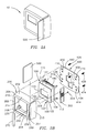
- FIGS. 3A and 3B illustrate and show an exploded view of a reconfigurable payment device including the reader head guide assembly mounted in an alternative position to that seen in FIGS. 2A and 2B to enable the reading of an electronic payment tool/mag swipe card by the reader head guide assembly.
- FIGS. 4 a -4 d are illustrations (back of device perspective) of the reconfigurable payment device, with the back plate removed, wherein the second housing and reader head guide assembly are presented in multiple orientations relative to and communicatively coupled with the first housing.
- FIG. 5 is a representative illustration of a wireless electronic payment system including a reconfigurable payment device in communication with an electronic payment transaction processing network.
- FIG. 6 is a block diagram illustrating a method for the performance of an electronic payment transaction.
- This invention consists of a reconfigurable electronic transaction payment apparatus (the “device”) generally configured with component features comprising a first and second housings, a reader head guide assembly and a back plate.
- the interconnection, both physical and communicatively, between these component features allows for the repositioning of the second housing about the first housing.
- This repositioning of the second housing further allows for the repositioning of the reader head guide assembly.
- the repositioning of the reader head guide assembly allows the position of the card swipe reader that is presented to a user for the swiping of a user's card to be moved about the device. This enables the card swipe reader to be moved away from or avoid any obstacles that are presented by the surface and/or object upon which the device is mounted.
- the shape of the device is defined as cubical or box-like, however, alternate polygonal configurations, dimensions, and contouring may be employed to define the overall shape of the device.
- the reconfigurable device enables the performance of actions in the process of an electronic payment transaction. More specifically, the device allows a user to perform a “card swipe” of their credit or debit card. From the card swipe the device collects the payment information from the credit or debit card and communicates necessary information to and receives information from a transaction processing network. It is to be understood that communication between the device and the transaction processing network is accomplished through the use of a wireless communication system, which can communicate using encryption protocols, such as the encrypted Zigbee protocol.
- the means of communication employed by the device may vary, such as a wired or wireless communication means, and may include variation in the hardware employed, protocols used, encryption(s) used, and any other aspects or functional capabilities that are used to provide the communication functionality for the device without departing from the scope and spirit of the current invention. It is also contemplated that the communication means of the device enable its communication with various other computing devices and networks.
- the device 10 is established with the following dimensions: width of 4.5 inches, height of 3.875 inches and depth of 1.25 inches.
- the device 10 provides a display 122 that is a high visibility, graphical liquid crystal display.
- the size of the display 122 may vary, preferably ranging from 2 inches to 4 inches, but may be of any size contemplated.
- the housings are made from thermal plastic through an injection molding process. The material provides an impact resistance for the device.
- the device 10 accepts AC or DC power from 9V up to and including 30V. The power may be provided to the device directly from a machine to which the device is connected or via an additional power adapter that taps the line voltage and provides 24VDC.
- the current invention comprises two such power adapters, one for 110VAC and another for 220VAC.
- Optimal operation ranges include temperature range from 41° F. to 104° F. (+5° C. to +40° C.) and humidity range from 20%-80%, relative, and non-condensing. It is to be understood that the device can operate outside of these optimal ranges.
- the back plate may be integral with the first housing, the component features included may vary, the generally planar nature of the surfaces of the device may be altered and the size of the device, including the component features presented by the device, may be enlarged or reduced.
- the communication system and protocols may be varied, the display may use alternative technologies, differing power requirements may be used and optimal operation ranges may increase or decrease relative to those previously stated.
- the first housing 100 may be referred to as an “inner base assembly”, “puck assembly” or “puck”.
- the puck 100 is constructed of a durable material, such as a plastic material, and may be constructed by various processes, such as an injection molding process, forming the puck 100 into a desired shape. However, other materials and methods of construction may be used to provide the puck of the current invention.
- the puck 100 comprises a plate 102 having an outer (“face”) surface 104 and inner surface 106 defined by top 107 , bottom 108 , right 109 and left 110 edges.
- An access point 120 (e.g., plate cut-out) extends through and creates a receiving area within the plate 102 .
- a display 122 Located within the access point 120 is a display 122 , which provides a user perceptible display of information.
- a keypad overlay 126 is established on the outer surface 104 proximal to the display 122 .
- the plate, walls and posts shall have defined dimensions that enable the coupling of the puck 100 with a second housing 200 (defined below) of the reconfigurable payment device 10 of the current invention.
- a printed circuit board (PCB) 180 Connected to the inner surface 106 of the puck 100 is a printed circuit board (PCB) 180 that is operationally coupled with various component features, including the display 122 , keypad overlay 126 and others.
- the plate 102 generally establishes a planar outer surface for the puck 100 .
- the dimensions of the plate 102 are established to enable its connection and operation with the second housing 200 of the device 10 .
- the outer surface 104 of the puck may exhibit, entirely or only in part, a non-planar shape, such as a curved or contoured shape.
- the outer surface 104 may be established with a dome-shaped or arc-shaped contouring. Any amount of curvature or contouring provided to the outer surface 104 of the puck plate 102 shall ensure the usability of component features of the puck 100 and its functional capability as a component feature of the device 10 .
- any curvature or contouring provided may be “gentle” in its amount.
- a component feature of the puck 100 is the display 122 .
- the dimensional characteristics of the display 122 are as previously described and shown but may vary to accommodate desired design characteristics. As shown in FIGS. 1-3 the display configuration allows its establishment within the dimensional restraints of the access point 120 . It is understood that the display 122 further defines the outer surface 104 of the puck 100 . Alternatively, the display 122 may be established in a non-planar (not flush) relationship with the rest of the outer surface 104 of the puck plate 102 . For instance, the display 122 surface may be recessed from the generally planar surface provided by the outer surface 104 of the puck plate 102 .
- the display 122 may comprise various technologies, such as liquid crystal display (LCD), and other known technologies, to provide a visual display of information to a user. It is contemplated that the display 122 may use other technologies to enable user interaction with the device, such as through use of touch-screen technologies. It is understood that the dimensional characteristics of the display 122 may vary in accordance with the dimensions of the access point 120 . The display 122 is not necessarily required to entirely occupy the dimensions of the access point 120 , but that it provides a display of information, which is readable. In operation, where the device 10 is established for use with a particular machine, the display 122 is enabled to make interconnections to the machine, through the PCB 180 , and is capable of operation using the wiring of the machine.
- LCD liquid crystal display
- the keypad overlay 126 allows user interaction with the device 10 and further defines the outer surface 104 of the puck plate 102 .
- the keypad overlay 126 generally covers the entire outer surface 104 of the puck 102 , with a clear window allowing the display 122 to be viewed.
- the keypad overlay 126 may only partially encompass the outer surface 104 of the puck 100 and may be generally positioned on the outer surface 104 , such as below the display 122 , or in various positions about the outer surface 104 . It is contemplated that other component features, such as buttons or other user interactive mechanisms, may further be included on and/or define the outer surface of the puck.
- Component features that are included on the outer surface 104 of the puck 100 can generally promote the planar nature of the outer surface 104 or may not. It is to be understood that the display 122 , keypad overlay 126 , buttons and/or other such user interactive mechanisms may provide contouring to and/or extend a certain distance above the plane of the outer surface 104 without diverging from the intent and operational performance needs of the device 10 .
- the PCB 180 Connected to the inner surface 106 of the puck plate 102 is the printed circuit board (PCB) 180 . It is contemplated that the PCB 180 be integrally or removably connected with the inner surface 106 of the puck plate 102 .
- the PCB 180 is configured to fit within the dimensional restrictions of the inner surface 106 , inner walls ( 112 - 115 ) and inner posts ( 130 , 32 , 134 and 136 ) that extend from the edges ( 107 - 110 ) of the inner surface 106 .
- the connection of the PCB 180 is made through the use of fasteners, such as screws, that connect to the inner surface 106 of the puck plate 102 . It is contemplated that various connection mechanisms and technologies may be used to connect the PCB 180 , and other device component features, with and/or to the inner surface 106 or other component features of the puck 100 .
- the PCB 180 is operationally coupled with the display 122 and keypad overlay 126 and provides a designed surface upon which other component features can be mounted and operationally coupled with various component features of the device 10 and/or machine to which the device 10 is communicatively connected.
- the component features of the PCB 180 can include one or more machine interface circuits, an internal power supply, wired or wireless communication (receipt and transmission) circuits and capabilities, a communication connector 182 (e.g., read head connector) and such other additional logical circuits/controls, adapters and connectors that enable desired functional capabilities of the device as may be contemplated.
- a connector to the PCB 180 be provided that allows for the reprogramming of the device.
- the PCB 180 may include a connector for an radio frequency identification (RFID) reader and various other external devices.
- RFID radio frequency identification
- the various component features of the PCB 180 enable the functionality of the device 10 .
- This functionality may include acceptance of payment cards (i.e., magnetic stripe payment card type), gift/loyalty cards and non-payment cards (e.g., maintenance cards—these cards are not payment cards, they allow the reader to perform other tasks such as self-test and to place the machine into service mode).
- MDB multi drop bus
- Ability to replace laundry connector board with other connector boards such as a multi drop bus (MDB) vending connector board to allow use with any MDB compliant vending machine, including soap dispensers and/or soda machines.
- the four inner posts ( 130 , 132 , 134 and 136 ) and walls ( 112 - 115 ) extend a defined distance from the inner or bottom surface 106 to facilitate the secure connection, coupling and/or seating of the puck assembly 100 to, with and/or upon other objects, such as the second housing 200 (or “ring assembly) of the current invention.
- the inner walls and posts of the puck 100 are integral with the inner surface 106 of the puck plate 102 .
- the inner walls and posts are also integrally formed in connection with one another.
- the walls and posts of the puck may be various inter-connectable component features. This may promote a modular approach to the construction and establishment of the walls, posts, puck and overall device of the current invention.
- each post furthest from the inner surface 106 of the puck plate 102 , is a post tab or stop ( 131 , 133 , 135 and 137 ).
- the post tab or stop is oriented in a generally perpendicular relation to the plane of the post and extends a distance from the post suitable for the performance of its function (described herein). It is understood that the orientation and dimensional characteristics of the stops ( 131 , 133 , 135 and 137 ), including the distance it extends from a post, may vary to accommodate the operational needs of the current invention.
- the stops ( 131 , 133 , 135 and 137 ) engage or seat against the post receiver stop ( 231 , 233 , 235 and 237 ) to provide a position for the puck assembly 100 relative to the ring assembly 200 when the puck assembly 100 is inserted or seated within the ring assembly 200 .
- the position provided for the puck assembly 100 relative to the ring assembly 200 by the engagement of the post stops ( 131 , 133 , 135 and 137 ) with the post receiver stops ( 231 , 233 , 235 and 237 ) is intended as an operational position.
- the physical connection provided by engaging the post stops ( 131 , 133 , 135 and 137 ) against the post receiver stops (inner ledges) ( 231 , 233 , 235 and 237 ) is one of a non-integral, non-locking, seated or temporary nature.
- the joining of the puck 100 with the second housing 200 or other objects may occur using various technologies and means as contemplated by skilled artisans.
- the ring assembly 200 may include aspects of a snap-fit mechanism with connectors found on the inner posts of the second housing, to provide a physical joining of the ring assembly with other objects.
- the inner posts of the ring assembly 200 may engage along their length in a friction fit manner with other objects. Regardless of the connection mechanism and technology being employed the repositioning capability of the reconfigurable electronic payment device is maintained.
- connection mechanisms are being used to connect the first housing with other objects it is contemplated that it may include a release mechanism.
- the release mechanism can enable a user to release the ring assembly from its connection with another object.
- alternative mechanisms to provide the release of the connection of the first housing with another object is contemplated, including manual, semi-automated and automated releasing means.
- the puck 100 may be variously configured wherein each of the different component features may be included together.
- the puck 100 may include a back surface that is similar in nature to that of the device back plate 400 herein described below.
- the back surface may be integral or non-integral with the rest of the puck.
- the back surface may be connected with an end of the four inner posts through the use of fasteners, such as screws, or by integrally forming the back surface to the ends of the posts.
- the back surface may be connected with inner walls that extend from the inner surface.
- the puck may be defined as only four posts that can directly connect with the various required component features for the device.
- the posts may be positioned to generally establish a square shape for the puck, similar to that shown in FIG. 1 , but not be directly connected with one another.
- the puck 100 may be configured to include the physical connectors necessary to secure the connection of the puck with the ring.
- a ledge multiple tabs or stops may be established about the back surface with can engage with features of the ring assembly to optimally position the puck when inserted or seated within the ring.
- the back surface may provide a generally “flanged” appearance relative to the rest of the puck when being established to connect with the ring.
- the back surface can allow for the use of fasteners, such as screws, to secure the connection of the puck with the ring. It can be that the use of fasteners optimally positions the puck within the ring or that the fasteners simply secure the connection.
- the back surface when configured to promote the connection of the puck with the ring, may also be configured to provide at least a partially enclosed environment for the device.
- the back surface similar to the back plate described below, can allow for the communicative coupling between the device and a machine to which it is operationally connected.
- the current configuration establishes a partially enclosed puck environment through or within which component features for the device 10 are located. It is contemplated that the puck 100 may establish a fully enclosed environment within which the component features are located.
- the nature of the enclosure established by the puck assembly 100 may be defined in conformance with specifications provided and/or requirements to be complied with.
- the design and construction of the puck 100 may be based upon conformance with various aesthetic requirements, such as the aesthetics of the location of use of the device. For instance, where a laundry machine is constructed to provide a non-linear aesthetic, the device, and therefore the puck, may be designed and constructed to match the non-linear nature of that laundry machine. Regardless of the nature of the configuration constructed for the puck, the surfaces and/or posts will still provide the foundation for the joining of the puck with the second housing.
- the puck 100 is capable of being established using modular component feature(s). It is contemplated that to provide the reconfiguration capabilities and maintain the desired operational characteristics of the puck 100 that such a “modular” puck can be enabled with a first housing connection mechanism or assembly.
- the first housing connection assembly can include physical connectors such as the four inner posts and walls that connect to the inner surface of the plate and then promote the coupling of the puck with the ring assembly.
- the modular first housing connection assembly may include only four posts or only four walls for connecting with the ring assembly.
- modular component features such as various connectors, tabs and/or stops can be disposed about the puck to engage the puck with other objects, such as with the ring assembly.
- the number and dimensional characteristics of the posts and walls may vary as well as the location where such features are established on the puck. For instance, the height and thickness of the posts, walls and/or other modular component features may be varied to provide sufficient structural and/or performance support for the device.
- the component features for the first housing connection mechanism are configured to connect with both the puck and other objects, such as the ring assembly.
- these component features can connect on one end with the inner surface of the plate of the puck and on the other end with the ring assembly.
- the manner of establishing the connection of these component features with other components of the reconfigurable device can occur through the use of various connecting mechanisms. For instance, a friction fit mechanism, snap-fit mechanism, compression lock mechanism, quick-release mechanism, and the like may be employed. It is contemplated that the connection mechanism employed will facilitate the release of a connection established between the component features and the puck or ring assembly.
- the connectors of the first housing connection mechanism may enable or allow for a physical connection between the first housing and another object in a permanent or increasingly permanent manner. It is understood that the first housing connection mechanism is part of enabling the repositioning of the second housing about the first housing. The repositioning capability enabled by the first housing connection mechanism does not limit any other functional aspect performed by the reconfigurable electronic payment device of the current invention.
- the first housing connection mechanism may be established on alternative features of the puck.
- the physical connectors may be included on the back surface.
- the back surface may include a physical connection mechanism that is a snap-fit connection mechanism allowing for connection between the first housing and second housing.
- the physical connection mechanism may be established in various locations about the puck without departing from the scope and spirit of the current invention.
- Other connection technologies such as compression locks, quick release connectors, friction fit, and others may be employed upon the back surface or other various locations about the puck.
- the second housing 200 is an outer housing that may be referred to as the “ring assembly” or “ring”.
- the ring 200 is constructed from molded plastic materials. However, other materials and methods of construction may be used to accomplish construction of the ring 200 .
- the body of the ring 200 comprises four integral walls 202 , 203 , 204 and 205 , including four corners 206 , 207 , 208 and 209 , that generally establish a hollowed out assembly having a defined top surface 210 , bottom surface 212 , outer surface 214 and inner surface 216 .
- the surfaces of the body may provide varying dimensional characteristics. For instance, in embodiments the bottom surface 212 is defined primarily as a circumferential edge while the outer surfaces 214 or sides of the device provide a nearly continuous wall that defines the depth of the ring 200 , which enables its operation with the puck assembly 100 .
- the top surface 210 can be defined as establishing a generally planar surface area for the device 10 . However, the top surface 210 does provide the operation and use of component features of the ring assembly 200 and the puck assembly 100 .
- the top surface 210 is enabled to provide access for the swiping of an electronic payment tool (a magnetic payment card, such as a credit/debit card, gift or loyalty card) by a magnetic card receiver 250 (the “mag card receiver” or “receiver”).
- the receiver 250 enabling the swiping of the electronic payment tool through the device 10 , establishes a slot 252 along a length of the body extending a certain depth from the top surface 210 towards the bottom surface 212 .
- a plate 270 may be connected with or integral to an area of the top surface 210 of the body. The plate 270 may provide information to a user of the device 10 , such as instructions for using the device.
- the inner surface 216 includes various component features disposed upon it.
- integral with the inner surface 216 are four post receivers 230 , 232 , 234 and 236 , four back plate connectors 240 , 242 , 244 and 246 and a reader head guide assembly adapter 290 .
- Other component features can be included upon the surfaces of the ring assembly 200 and, as described herein, the various component features can include additional aspects.
- the top surface 210 is further defined by a puck assembly receiver 240 , which is generally established as a space within the top surface 210 that extends through and creates a hollow within the top surface 210 of the ring 200 .
- the dimensions of this access space 240 are defined to enable the operation of the puck assembly 100 when it is seated within the ring 200 . This includes providing for the viewing of and access to the display 122 and/or keypad overlay 126 of the puck 100 .
- the access space 240 dimensional characteristics can be adjusted to accommodate variations in dimensions of different puck designs.
- the general shape of the ring 200 is established to allow for the connection of the ring 200 with the puck 100 . Therefore, overall conformance between the shape of both the puck 100 and ring 200 can be a critical aspect of the current invention. However, it is contemplated that the overall shape of the puck may differ from the overall shape of the ring without departing from scope and spirit of the current invention.
- the dimensional characteristics of the ring 200 comprising the length, width, and height of its various surfaces, are consistent with industry standard requirements that are met by the electronic payment device 10 of the current invention. It is understood that the surfaces and component features of the ring may be constructed and comprise various dimensional characteristics. It is further contemplated that changes may be made to the generally planar nature of the top surface of the ring without diverging from the intent and operational performance needs of the current invention.
- a status indication assembly may be included in the ring.
- the status indication assembly can comprise visual indicators that can be perceived by a user to inform the user of the current operational status of the device.
- the visual indicators may be one or more LEDs that indicate the status of the swipe reader (e.g., green for ready, red for busy, flashing while reading, and the like).
- the various surfaces and component features of the ring 200 herein described are generally integral with one another. Thus, each provides a continuous surface for the ring 200 . It is alternatively contemplated that the surface and/or component features of the body of the ring may be modular surface and/or component features capable of being interconnected with and to one another. Thus, it is contemplated that various different surface and/or component features, having various different dimensional characteristics, can be used to establish the ring and to provide the reconfiguration capabilities of the device of the current invention.
- the current configuration of the inner surface 216 of the ring 200 establishes a partially enclosed ring environment through or within which the puck assembly 100 may be seated. It is contemplated that the ring 200 may establish a more enclosed or open environment within which the puck assembly 100 and other component features may be seated and located.
- the nature of the enclosure established by the ring and/or puck assembly may be defined in conformance with specifications provided and/or requirements to be complied with.
- the design and construction of the ring 200 may be based upon conformance with various aesthetic requirements, such as the aesthetics of the location of use of the device. For instance, where a laundry machine is constructed to provide a non-linear aesthetic, the device, and therefore the ring, may be designed and constructed to match the non-linear nature of that laundry machine.
- the defined surfaces and post receivers may be of an integral or non-integral nature, regardless they provide the foundation for the joining of the ring with the first housing or other objects. As will be discussed below, the joining of the ring with the first housing or other objects may occur using various means as contemplated by skilled artisans.
- the top surface 210 of the ring 200 is a generally planar, unbroken surface that promotes and is in conformance with the generally planar nature of the top surface of the puck 100 .
- the mag card reader 250 is established as a slot 252 within the second housing 200 .
- the slot 252 opens through the top 210 and outer 214 surfaces of the second housing 200 and extends a determined distance into the second housing 200 .
- the distance the slot 252 extends enables the capture of information from the magnetic stripe contained on an electronic payment tool that is passed through the card swipe reader 252 . It is to be understood that this distance into the second housing 200 that the slot 252 extends may vary, but in no case shall the distance prohibit the passage of the magnetic stripe of and capture of information from the electronic payment tool 500 .
- the inner surface 216 includes a reader head guide assembly receiver 290 (the “reader head receiver”) for receiving a reader head guide assembly 300 .
- the reader head receiver 290 provides a location within the inner surface 216 of the ring 200 within which the reader head guide assembly 300 may be seated. It is further contemplated that the reader head receiver 290 include a connector which may be engaged by a fastener, such as a screw, that also engages with the reader head guide assembly 300 and secures its position. Other mechanisms for securing the position of the reader head guide assembly 300 relative to the rest of the ring assembly 200 and/or within the reader head receiver 290 may be used without departing from the scope and spirit of the current invention. For instance, it may include a snap-fit mechanism or enable a friction-fit type engagement with the reader head guide assembly.
- the reader head receiver 290 locates the reader head guide assembly 300 in proper position relative to the mag card receiver 290 .
- the mag card receiver 290 allows a user to swipe the magnetic stripe of their electronic payment tool 500 (e.g., a card) through the device 10 .
- the reader head receiver 290 enables the reader head guide assembly 300 , during the swipe of the card, to perform its function of reading information stored on the magnetic stripe of the card.
- the reader head guide assembly 300 can also “read” information from various electronic payment tools such as credit and/or debit cards or other such tools that store information on a magnetic stripe for reading by a device.
- the reader head guide assembly 300 seats within the ring 200 in relation to the reader head receiver 290 that enables the swipe of a magnetic stripe of an electronic payment tool 500 .
- This reader head guide assembly 300 enables the capture of information from the magnetic stripe when swiped through the adapter.
- the reader head guide assembly may provide an encryption capability.
- the reader head guide assembly 300 can encrypt the information gathered from the swiping of a mag swipe card before that information is communicated.
- Other reader head guide assemblies may be employed by the current invention that use bit/strobe or other SPI interface heads.
- the reader head guide assembly 300 is able to communicate this information to the PCB 180 through use of a standard communication assembly 320 that includes a cable 322 which plugs into the communication connector 182 (reader head connector) located on the PCB 180 .
- a standard communication assembly 320 that includes a cable 322 which plugs into the communication connector 182 (reader head connector) located on the PCB 180 .
- the current invention uses an SPI serial cable 322 connected with the proper functional aspects of the reader head guide assembly 300 on one end and with an adapter 323 on the opposite end. The adapter 323 then plugs into the PCB 180 of the puck assembly 100 .
- This communication assembly 320 is capable of allowing and/or maintaining the communicative coupling between the reader head guide assembly 300 and the PCB 180 regardless of the different configurations established by the device 10 . It is contemplated that the length of the cable 322 may be a determining factor in the size of the puck assembly 100 .
- the post receivers extend a defined distance along the inner surface 216 between the top 210 and bottom 212 surfaces of the ring 200 to facilitate connection of the ring 200 with other objects, such as the puck 100 .
- the posts 130 , 132 , 134 and 136 of the puck 100 seat loosely within the post receivers 230 , 232 , 234 and 236 of the ring 200 .
- the end of the post receivers nearest the bottom surface 212 of the ring 200 include post receiver stops 231 , 233 , 235 and 237 which engage with the post stops 131 , 133 , 135 and 137 found on the ends of the posts 130 , 132 , 134 and 136 on the puck 100 .
- This manner of engagement provided between the ring 100 and puck 200 assemblies promote the ease with which the puck 100 may be removed from and repositioned in relation to the ring 200 and thus the reconfiguration capability provided by the device 10 of the current invention.
- the dimensional characteristics of the post receivers 230 , 232 , 234 and 236 and post receiver stops 231 , 233 , 235 and 237 are determined to provide engagement with the posts and post stops that position the front or top surface of the puck (i.e., display and keypad overlay) in a generally planar alignment with the top surface of the ring. It is further understood that the dimensions of both the post receivers 230 , 232 , 234 and 236 , post receiver stops 231 , 233 , 235 and 237 , posts 130 , 132 , 134 and 136 and post stops 131 , 133 , 135 and 137 allow for the connection of the back plate 400 with the ring 200 in the manner described below.
- two of the post receivers are located at the two corners of the ring body opposite the location of the mag card receiver 290 and on opposite walls from each other. Another two post receivers are located proximal to the mag card receiver 290 of the ring 200 and on opposite walls from each other. It is contemplated that the number and location of the post receivers may vary to accommodate different post positioning and/or design needs without departing from the scope and spirit of the current invention.
- the posts of the puck and post receivers of the ring may include or enable various connection mechanisms and technologies. These may include a snap-fit mechanism, quick-release mechanisms, compression lock mechanism, friction-fit mechanism, and the like.
- the post receivers may include and/or enable various other mechanisms, such as release mechanisms. It is understood that the mechanisms and features that can be included with the device and/or upon the post receivers promote the reconfiguration capabilities of the device of the current invention.
- back plate connectors 240 , 242 , 244 and 246 are disposed about and connected with the inner surface 216 of the ring. These connectors are capable of being engaged by a fastener, such as a screw as shown, to promote the secure positioning of the back plate 400 relative to the ring 200 and puck 100 .
- a fastener such as a screw as shown
- two of the connectors are located at the two corners of the body opposite the location of the mag card receiver 290 and on opposite walls from each other.
- Another two connectors are located proximal to the mag card receiver 290 of the ring 200 and on opposite walls from each other. It is contemplated that the number and location of the connectors may vary to accommodate different design needs without departing from the scope and spirit of the current invention.
- a back plate 400 provides the back surface for the reconfigurable payment device 10 .
- the back plate may 400 be constructed of various materials, including but not limited to metals, plastics or other similar materials that meet the functional and structural requirements for the device.
- the back plate 400 includes ring connectors 410 , 412 , 414 and 416 that promote the connection of it with the ring assembly 200 .
- the ring connectors 410 , 412 , 414 and 416 of the back plate enable the use of fasteners, such as screws, to engage or pass through them and further engage with the back plate connectors 240 , 242 , 244 and 246 included on the inner surface 216 of the ring assembly 200 (discussed above).
- connection of the back plate 400 with the ring assembly 200 can provide a compression fit that holds the post tabs or stops 131 , 133 , 135 and 137 on the inner posts 130 , 132 , 134 and 136 of the puck 100 against the corresponding post receiver stops or ledges 231 , 233 , 235 and 237 found on the post receivers 230 , 232 , 234 and 236 of the ring 200 .
- Four compression pads can be disposed upon the back plate 400 , as shown in FIG. 2 , and are designed to engage against the post stops 131 , 133 , 135 and 137 of the puck 100 when the back plate 400 is connected to the ring 200 .
- the back plate 400 assists in the proper positioning of the puck 100 within the ring 200 , thereby further promoting the operation of the device 10 .
- alternative mechanisms for securing the positioning of the puck within the ring may be employed without departing from the scope and spirit of the current invention.
- the back plate 400 also promotes the mounting of the device 10 upon various machines and/or surfaces.
- a mounting assembly comprising a first 430 , second 432 , third 434 , and fourth 436 mounting receivers, is provided by the back plate 400 . It is contemplated that various other mechanisms, such as brackets, holders, and the like may be used to mount the device of the current invention.
- the back plate 400 includes a communications passage 450 that allows for the communicative coupling of the device 10 with another object, such as a machine upon which it may be mounted. In operation the passage 450 can allow for connection with the PCB 180 of the device 10 by cables, wires, or other communication equipment that is also connected with the machine to which the device 10 is mounted. The dimensions of the passage 450 may vary to accommodate design and/or operational needs.
- the device 10 may be mounted on various surfaces, including a surface(s) provided by a machine to which the operation of the device is associated.
- the device 10 may be mounted to a washer and/or dryer machine, vending machine and other objects which may utilize the electronic payment transactions capabilities provided by the device 10 .
- a mounting assembly provided by the back plate 400 of the current invention, may allow the device 10 to be mounted upon machines and/or surfaces. It is contemplated that a mounting assembly may be provided by the second housing 200 of the current invention. It is further contemplated that the mounting assembly is provided by an operational conjunction of both the back plate 400 and second housing 200 . It is to be understood that the mounting assembly may be removably connectable with or integral with either or both the back plate 400 and second housing 200 .
- the ring assembly 200 can be enabled with a second housing connection mechanism.
- the second housing connection assembly can include physical connectors such as the four post receivers, four back plate connectors and various surfaces and/or walls that connect to and with the inner surface 216 of the ring 200 and then promote the coupling of the ring 200 with the puck assembly 100 and back plate 400 .
- the second housing connection assembly may include only four post receivers or only four walls for connecting with the puck assembly and back plate.
- other component features, such as various connectors, tabs and/or stops can be disposed about the ring 200 to engage the ring with other objects, such as with the puck assembly 100 and back plate 400 .
- the component features, and therefore the second housing connection mechanism may be established in a modular manner providing the capability for these features to be connected and/or removed from the ring assembly 200 .
- the number and dimensional characteristics of the post receivers, back plate connectors, walls and/or surfaces may vary as well as the location where such features are established on the ring 200 .
- the height and thickness of the post receivers and/or other modular component features may be varied to provide sufficient structural and/or performance support for the device 10 .
- the component features for the second housing connection mechanism are configured to connect with the ring 200 , puck 100 , back plate 400 and other objects as desired.
- these component features can connect on one end with the inner surface 216 of the ring 200 and on the other end with the puck assembly 100 and/or back plate 400 .
- These features may be established in various locations about the inner surface 216 or on alternative features of the ring 200 and may employ various connection mechanisms to accomplish its function.
- the manner of establishing the connection of these component features with the ring 200 and other components of the reconfigurable device 10 can occur through the use of various connecting mechanisms. For instance, a friction fit mechanism, snap-fit mechanism, compression lock mechanism, quick-release mechanism, and the like may be employed.
- the second housing connection mechanism employed will facilitate the release of a connection established between the ring 200 , puck 100 , back plate 400 , and/or other objects.
- the second housing connection mechanism may include a release mechanism.
- the release mechanism can enable the connectors of the second housing to disengage from the connectors of another object.
- alternative mechanisms to provide for the release of the connection of the second housing with another object is contemplated, including manual, semi-automated and automated releasing means.
- the connectors of the second housing connection mechanism may enable or allow for a physical connection between the second housing and another object in a permanent or increasingly permanent manner. It is understood that the second housing connection mechanism is part of enabling the repositioning of the second housing about the first housing. The repositioning capability enabled by the second housing connection mechanism does not limit any other functional aspect performed by the reconfigurable electronic payment device of the current invention.
- the first and second housings establish an overall shape for the device.
- the shape is generally of a cube or squared cube.
- the ring 200 can be oriented in any of four orientations relative to the puck 100 , such that the swipe card reader is located to the right, left, bottom or top of the device. This allows the direction of a card swipe to be changed to avoid physical impediments, such as coin vaults, doors, or other obstructions, while leaving the orientation of the display and user input buttons constant.
- the outer dimensions of the puck 100 and inner dimensions of the ring 200 are similar when rotated 90°, 180° and 270°. These puck and ring dimensions have tolerances for assembly.
- the device 10 can exhibit a reflective symmetry along both the X and Y axes. Without compromising the operations of the device 10 this symmetry may be altered to any extent contemplated.
- the current invention contemplates alternative geometries for the shape of the device 10 .
- the device 10 may be configured in a generally triangular shape. It is further contemplated that the device 10 may be established in various other polygonal shapes, such as a pentagon, hexagon, octagon and other shapes, as are known and contemplated. Additionally, the shape of the device 10 may be established generally as a circle or modified circle. It is to be understood that any shape may be given the device 10 so long as operational performance is maintained.
- the device 10 can be used for any electronic payment or non-payment transaction need, such as small value purchase payment, loyalty/gift card use, maintenance card use and the like, where flexibility in swipe direction is needed, including but not limited to vending and arcade gaming machines.
- An electronic credit and/or debit transaction system 500 is provided in an embodiment of the current invention, as shown in FIG. 5 .
- the system comprises a reconfigurable electronic payment device 510 in communication with an electronic payment transaction processing network 520 .
- the means by which communication between the device and network are established may be any standard means, such as wired or wireless communication protocols, known to those skilled in the art.
- the electronic payment transaction processing network includes all necessary resources, authorities and capabilities for execution of an electronic credit and/or debit transaction.
- the system includes a wireless communications capability to enable communication between the device and other computing devices 540 , controllers 530 and/or networks, such as the electronic payment network 520 .
- the wireless capability may include the addition of a wireless communication technology into the electronic payment device 510 of the current invention.
- this technology may be included on the PCB of the current invention.
- the technology may be industry standard and/or include customized features and capabilities.
- a system with wireless capability for the current invention may comprise one or more of the reconfigurable electronic payment devices 510 of the current invention operationally connected with a machine (not shown), a wireless controller device 530 , and an electronic payment transaction network 520 .
- the operational connection amongst the various components of the system 500 can be established via communication over the Internet.
- the wireless controller device 530 is in communication with an additional computing device 540 .
- the reconfigurable electronic payment devices 510 can wirelessly communicate with the wireless controller 530 , providing information to and receiving information from the wireless controller 530 .
- the wireless controller 530 is also in communication with the transaction network 520 and any additional computing device(s).
- the system can execute electronic financial transactions through each device and control the operation of the machine to which the device is operationally coupled.
- the system can also provide additional capabilities. For instance, the system can allow users (cardholders/transaction requestors) to manage user's account, add value, view machine (i.e., laundry) status and establish alerts when the machine has finished.
- the system can allow operators (owners/vendors) to access transaction information, machine status and activity in a location.
- the functional capabilities of the system are provided on-demand and in real-time. This allows the users and operators to access and receive information regarding individual machine use and status, as well as information about multiple machines that can be located in one or more different locations or rooms.
- the systems and methods of the current invention may use various communication protocols and networks, from the Internet, to intranets, proprietary networks and such other platforms as may be contemplated for use. It is contemplated that the device may be in communication, either wired or wirelessly, with various other computing devices. These other computing devices can provide additional information to users and operators. In a laundry machine operating environment, this additional information may include the status of a wash cycle being performed or an update regarding the operational status of a machine, such as whether it is functioning properly.
- the current invention provides a method 600 for performing an electronic credit or debit payment transaction, shown in FIG. 6 .
- a reconfigurable electronic payment device is established in a physical location that allows for the capture of payment information. This may include establishing the reconfigurable electronic payment device upon a laundry machine. Alternatively, this may include establishing the device on various types of vending machines, kiosk structures, as a stand-alone device, upon a wall or any other structure as is contemplated for the device of the current invention.
- the payment information is transmitted to an electronic payment transaction processing network. The execution of all required steps for the performance of an electronic transaction, outside that performed by the device of the current invention, is carried out by and over the network.
- the device may communicate with various networks and protocols established by those networks. This may include, but should not be interpreted as limited to, various security/encryption protocols that may be promulgated over an electronic payment transaction network.
- transaction authorization information is transmitted from the electronic payment transaction processing network to the device.
- Additional method steps may include the transmission of payment information to a wireless controller device and then transmission from the wireless controller device to an electronic payment transaction network. It is further contemplated that the transaction authorization may be transmitted form the network to an alternative location, such as the wireless controller and/or other computing devices.
- the device After the authorization information is transmitted to the device, the device through its logic controls may authorize the performance of a task. Where a device is mounted and in communication with a laundry machine, the authorized task may be for the machine to perform a wash and/or dry cycle. In a vending environment it may authorize the dispensing of a product. Where the authorization information transmitted to the device is a denial of the requested transaction then the user may be prompted to take additional steps. The additional steps may include, displaying a request on the display for the user to provide an alternative form of payment. Other method steps, as may be contemplated by those skilled in the art, can be performed without departing from the scope and spirit of the current invention.
- references(s) to or the appearance of the phrase “one embodiment” or “an embodiment” means at least one and that they are not necessarily all referring to the same embodiment nor that separate or alternative embodiments must be mutually exclusive of other embodiments. It does mean that a particular feature, structure, or characteristic described in connection with the embodiment is included in at least one embodiment but not necessarily included in all. Similarly, various requirement are described which may be requirements for one embodiment but not other embodiments. Unless excluded by explicit description and/or apparent incompatibility, any combination of various features described in this description is also included herein.
Landscapes
- Engineering & Computer Science (AREA)
- General Physics & Mathematics (AREA)
- Physics & Mathematics (AREA)
- Theoretical Computer Science (AREA)
- Computer Vision & Pattern Recognition (AREA)
- Artificial Intelligence (AREA)
- Control Of Vending Devices And Auxiliary Devices For Vending Devices (AREA)
- Business, Economics & Management (AREA)
- Microelectronics & Electronic Packaging (AREA)
- General Business, Economics & Management (AREA)
- Strategic Management (AREA)
- Accounting & Taxation (AREA)
- Computer Networks & Wireless Communication (AREA)
Abstract
Description
Claims (20)
Priority Applications (1)
| Application Number | Priority Date | Filing Date | Title |
|---|---|---|---|
| US14/106,738 US9530030B2 (en) | 2012-12-14 | 2013-12-14 | Reconfigurable payment device |
Applications Claiming Priority (3)
| Application Number | Priority Date | Filing Date | Title |
|---|---|---|---|
| US201261797769P | 2012-12-14 | 2012-12-14 | |
| US201261797679P | 2012-12-14 | 2012-12-14 | |
| US14/106,738 US9530030B2 (en) | 2012-12-14 | 2013-12-14 | Reconfigurable payment device |
Publications (2)
| Publication Number | Publication Date |
|---|---|
| US20140166747A1 US20140166747A1 (en) | 2014-06-19 |
| US9530030B2 true US9530030B2 (en) | 2016-12-27 |
Family
ID=50929787
Family Applications (1)
| Application Number | Title | Priority Date | Filing Date |
|---|---|---|---|
| US14/106,738 Expired - Fee Related US9530030B2 (en) | 2012-12-14 | 2013-12-14 | Reconfigurable payment device |
Country Status (1)
| Country | Link |
|---|---|
| US (1) | US9530030B2 (en) |
Families Citing this family (5)
| Publication number | Priority date | Publication date | Assignee | Title |
|---|---|---|---|---|
| JP1485286S (en) * | 2013-04-26 | 2016-11-21 | ||
| JP1485287S (en) * | 2013-04-26 | 2016-11-21 | ||
| US10044710B2 (en) | 2016-02-22 | 2018-08-07 | Bpip Limited Liability Company | Device and method for validating a user using an intelligent voice print |
| USD865859S1 (en) * | 2017-12-03 | 2019-11-05 | David Ben Avi | Cashless payment device for unattended machines |
| CN221040033U (en) * | 2023-09-28 | 2024-05-28 | 东莞富强电子有限公司 | Card reader with protection mechanism |
Citations (4)
| Publication number | Priority date | Publication date | Assignee | Title |
|---|---|---|---|---|
| US20020032875A1 (en) * | 2000-07-28 | 2002-03-14 | Mehdi Kashani | Information processing apparatus and method |
| US20030132294A1 (en) * | 2002-01-11 | 2003-07-17 | Hand Held Products, Inc. | Transaction terminal including signature entry feedback |
| US20050236480A1 (en) * | 2004-04-23 | 2005-10-27 | Virtual Fonlink, Inc. | Enhanced system and method for wireless transactions |
| JP2009112384A (en) * | 2007-11-02 | 2009-05-28 | Olympia:Kk | Game machine |
-
2013
- 2013-12-14 US US14/106,738 patent/US9530030B2/en not_active Expired - Fee Related
Patent Citations (4)
| Publication number | Priority date | Publication date | Assignee | Title |
|---|---|---|---|---|
| US20020032875A1 (en) * | 2000-07-28 | 2002-03-14 | Mehdi Kashani | Information processing apparatus and method |
| US20030132294A1 (en) * | 2002-01-11 | 2003-07-17 | Hand Held Products, Inc. | Transaction terminal including signature entry feedback |
| US20050236480A1 (en) * | 2004-04-23 | 2005-10-27 | Virtual Fonlink, Inc. | Enhanced system and method for wireless transactions |
| JP2009112384A (en) * | 2007-11-02 | 2009-05-28 | Olympia:Kk | Game machine |
Also Published As
| Publication number | Publication date |
|---|---|
| US20140166747A1 (en) | 2014-06-19 |
Similar Documents
| Publication | Publication Date | Title |
|---|---|---|
| US9530030B2 (en) | Reconfigurable payment device | |
| US10977392B2 (en) | Fuel dispenser user interface system architecture | |
| US9864971B2 (en) | Secure self-checkout station | |
| CN108025899B (en) | Beverage Dispensing Device with Smart Cup Label Identification and Verification | |
| US9665690B2 (en) | Secure cabinet for dispensing items | |
| US6223984B1 (en) | Distinct smart card reader having wiegand, magnetic strip and bar code types emulation output | |
| EP4057240B1 (en) | Self-service modular drop safes | |
| CA3077485C (en) | Point-of-sale system | |
| EP2551813B1 (en) | Self-service terminal | |
| US11593782B2 (en) | Fueling station transaction system and method | |
| AU2019284055B2 (en) | Alphanumeric keypad for fuel dispenser system architecture | |
| CN101911584A (en) | Transmitter for transmitting a secure access signal | |
| CA2311811A1 (en) | Self-service kiosk with biometrics verification and/or registration capability | |
| CN105386679B (en) | Security safe cabinet | |
| US10808449B1 (en) | Adjustable locker system | |
| US9189812B2 (en) | Kiosk and method for renting carpet cleaning machines | |
| JP2021014757A (en) | Key management system | |
| TW202207686A (en) | Remote desktop support kiosk and dispenser | |
| US20160086417A1 (en) | Vending machine with wireless-enabled currency acceptor | |
| CN214279067U (en) | Self-service beverage vending machine with anti-mistake-changing function | |
| CN217061103U (en) | Distributed automatic vending system | |
| UA100834C2 (en) | Complex system for sale of goods |
Legal Events
| Date | Code | Title | Description |
|---|---|---|---|
| AS | Assignment |
Owner name: HEARTLAND PAYMENT SYSTEMS, INC., NEW JERSEY Free format text: ASSIGNMENT OF ASSIGNORS INTEREST;ASSIGNORS:WORMSLEY, JEFFREY;PRICE, LEANNE;FARMER, RON;REEL/FRAME:031783/0679 Effective date: 20131213 |
|
| AS | Assignment |
Owner name: BANK OF AMERICA, N.A., AS ADMINISTRATIVE AGENT, IL Free format text: SECURITY AGREEMENT;ASSIGNOR:HEARTLAND PAYMENT SYSTEMS, INC., AS GRANTOR;REEL/FRAME:032379/0189 Effective date: 20140228 |
|
| AS | Assignment |
Owner name: HEARTLAND PAYMENT SYSTEMS, INC., NEW JERSEY Free format text: RELEASE OF PATENT SECURITY INTEREST;ASSIGNOR:BANK OF AMERICA, N.A., AS ADMINISTRATIVE AGENT;REEL/FRAME:038507/0381 Effective date: 20160422 |
|
| AS | Assignment |
Owner name: BANK OF AMERICA, N.A., AS ADMINISTRATIVE AGENT, TEXAS Free format text: NOTICE OF GRANT OF SECURITY INTEREST IN PATENTS;ASSIGNOR:HEARTLAND PAYMENT SYSTEMS, LLC;REEL/FRAME:038522/0861 Effective date: 20160422 Owner name: BANK OF AMERICA, N.A., AS ADMINISTRATIVE AGENT, TE Free format text: NOTICE OF GRANT OF SECURITY INTEREST IN PATENTS;ASSIGNOR:HEARTLAND PAYMENT SYSTEMS, LLC;REEL/FRAME:038522/0861 Effective date: 20160422 |
|
| AS | Assignment |
Owner name: HEARTLAND PAYMENT SYSTEMS, LLC, GEORGIA Free format text: MERGER AND CHANGE OF NAME;ASSIGNORS:HEARTLAND PAYMENT SYSTEMS, INC.;DATA MERGER SUB TWO, LLC;REEL/FRAME:038447/0873 Effective date: 20160422 |
|
| STCF | Information on status: patent grant |
Free format text: PATENTED CASE |
|
| AS | Assignment |
Owner name: NUEIP, LLC, UTAH Free format text: RELEASE BY SECURED PARTY;ASSIGNOR:BANK OF AMERICA, N.A.;REEL/FRAME:050406/0851 Effective date: 20190917 Owner name: NUESOFT TECHNOLOGIES INC., UTAH Free format text: RELEASE BY SECURED PARTY;ASSIGNOR:BANK OF AMERICA, N.A.;REEL/FRAME:050406/0851 Effective date: 20190917 Owner name: NEXTEP SYSTEMS INC., MICHIGAN Free format text: RELEASE BY SECURED PARTY;ASSIGNOR:BANK OF AMERICA, N.A.;REEL/FRAME:050406/0851 Effective date: 20190917 Owner name: GLOBAL PAYMENTS INC., GEORGIA Free format text: RELEASE BY SECURED PARTY;ASSIGNOR:BANK OF AMERICA, N.A.;REEL/FRAME:050406/0851 Effective date: 20190917 Owner name: ADVANCEDMD, INC., UTAH Free format text: RELEASE BY SECURED PARTY;ASSIGNOR:BANK OF AMERICA, N.A.;REEL/FRAME:050406/0851 Effective date: 20190917 Owner name: XENIAL, INC. (F/K/A HEARTLAND COMMERCE, INC.), GEO Free format text: RELEASE BY SECURED PARTY;ASSIGNOR:BANK OF AMERICA, N.A.;REEL/FRAME:050406/0851 Effective date: 20190917 Owner name: TOUCHNET INFORMATION SYSTEMS, INC., GEORGIA Free format text: RELEASE BY SECURED PARTY;ASSIGNOR:BANK OF AMERICA, N.A.;REEL/FRAME:050406/0851 Effective date: 20190917 Owner name: DEBITEK, INC., GEORGIA Free format text: RELEASE BY SECURED PARTY;ASSIGNOR:BANK OF AMERICA, N.A.;REEL/FRAME:050406/0851 Effective date: 20190917 Owner name: HEARTLAND PAYMENT SYSTEMS, LLC, GEORGIA Free format text: RELEASE BY SECURED PARTY;ASSIGNOR:BANK OF AMERICA, N.A.;REEL/FRAME:050406/0851 Effective date: 20190917 Owner name: ACTIVE NETWORK, LLC, TEXAS Free format text: RELEASE BY SECURED PARTY;ASSIGNOR:BANK OF AMERICA, N.A.;REEL/FRAME:050406/0851 Effective date: 20190917 Owner name: XENIAL, INC. (F/K/A HEARTLAND COMMERCE, INC.), GEORGIA Free format text: RELEASE BY SECURED PARTY;ASSIGNOR:BANK OF AMERICA, N.A.;REEL/FRAME:050406/0851 Effective date: 20190917 |
|
| FEPP | Fee payment procedure |
Free format text: MAINTENANCE FEE REMINDER MAILED (ORIGINAL EVENT CODE: REM.); ENTITY STATUS OF PATENT OWNER: LARGE ENTITY |
|
| LAPS | Lapse for failure to pay maintenance fees |
Free format text: PATENT EXPIRED FOR FAILURE TO PAY MAINTENANCE FEES (ORIGINAL EVENT CODE: EXP.); ENTITY STATUS OF PATENT OWNER: LARGE ENTITY |
|
| STCH | Information on status: patent discontinuation |
Free format text: PATENT EXPIRED DUE TO NONPAYMENT OF MAINTENANCE FEES UNDER 37 CFR 1.362 |
|
| FP | Lapsed due to failure to pay maintenance fee |
Effective date: 20201227 |