US9528880B2 - Method and system for gas temperature measurement - Google Patents
Method and system for gas temperature measurement Download PDFInfo
- Publication number
- US9528880B2 US9528880B2 US13/969,186 US201313969186A US9528880B2 US 9528880 B2 US9528880 B2 US 9528880B2 US 201313969186 A US201313969186 A US 201313969186A US 9528880 B2 US9528880 B2 US 9528880B2
- Authority
- US
- United States
- Prior art keywords
- filaments
- temperature
- emissivity
- temperature indication
- diameter
- Prior art date
- Legal status (The legal status is an assumption and is not a legal conclusion. Google has not performed a legal analysis and makes no representation as to the accuracy of the status listed.)
- Expired - Fee Related, expires
Links
- 238000009529 body temperature measurement Methods 0.000 title claims abstract description 79
- 238000000034 method Methods 0.000 title claims description 65
- 230000005855 radiation Effects 0.000 claims abstract description 61
- 230000003287 optical effect Effects 0.000 claims description 24
- 238000012544 monitoring process Methods 0.000 claims description 12
- 239000012530 fluid Substances 0.000 claims description 10
- CURLTUGMZLYLDI-UHFFFAOYSA-N Carbon dioxide Chemical compound O=C=O CURLTUGMZLYLDI-UHFFFAOYSA-N 0.000 claims description 7
- 238000004616 Pyrometry Methods 0.000 claims description 6
- 230000001131 transforming effect Effects 0.000 claims description 5
- 238000010521 absorption reaction Methods 0.000 claims description 4
- 229910002092 carbon dioxide Inorganic materials 0.000 claims description 4
- 239000001569 carbon dioxide Substances 0.000 claims description 4
- 238000002485 combustion reaction Methods 0.000 claims description 4
- 238000004891 communication Methods 0.000 claims description 3
- OKTJSMMVPCPJKN-UHFFFAOYSA-N Carbon Chemical compound [C] OKTJSMMVPCPJKN-UHFFFAOYSA-N 0.000 claims description 2
- VYPSYNLAJGMNEJ-UHFFFAOYSA-N Silicium dioxide Chemical compound O=[Si]=O VYPSYNLAJGMNEJ-UHFFFAOYSA-N 0.000 claims description 2
- 239000005350 fused silica glass Substances 0.000 claims description 2
- 229910002804 graphite Inorganic materials 0.000 claims description 2
- 239000010439 graphite Substances 0.000 claims description 2
- 229910052594 sapphire Inorganic materials 0.000 claims description 2
- 239000010980 sapphire Substances 0.000 claims description 2
- HBMJWWWQQXIZIP-UHFFFAOYSA-N silicon carbide Chemical compound [Si+]#[C-] HBMJWWWQQXIZIP-UHFFFAOYSA-N 0.000 claims description 2
- 229910001220 stainless steel Inorganic materials 0.000 claims description 2
- 239000010935 stainless steel Substances 0.000 claims description 2
- WFKWXMTUELFFGS-UHFFFAOYSA-N tungsten Chemical compound [W] WFKWXMTUELFFGS-UHFFFAOYSA-N 0.000 claims description 2
- 229910052721 tungsten Inorganic materials 0.000 claims description 2
- 239000010937 tungsten Substances 0.000 claims description 2
- XLYOFNOQVPJJNP-UHFFFAOYSA-N water Substances O XLYOFNOQVPJJNP-UHFFFAOYSA-N 0.000 claims description 2
- 230000008878 coupling Effects 0.000 claims 1
- 238000010168 coupling process Methods 0.000 claims 1
- 238000005859 coupling reaction Methods 0.000 claims 1
- 229910010271 silicon carbide Inorganic materials 0.000 claims 1
- 239000007789 gas Substances 0.000 description 152
- 230000006870 function Effects 0.000 description 16
- 238000011088 calibration curve Methods 0.000 description 9
- 230000007246 mechanism Effects 0.000 description 8
- 238000005259 measurement Methods 0.000 description 7
- 238000012937 correction Methods 0.000 description 5
- 238000009826 distribution Methods 0.000 description 5
- 230000000694 effects Effects 0.000 description 4
- 238000003491 array Methods 0.000 description 3
- 238000004590 computer program Methods 0.000 description 3
- 238000001816 cooling Methods 0.000 description 3
- 238000001514 detection method Methods 0.000 description 3
- 239000000446 fuel Substances 0.000 description 3
- 238000004519 manufacturing process Methods 0.000 description 3
- 239000000463 material Substances 0.000 description 3
- 239000011159 matrix material Substances 0.000 description 3
- 239000000567 combustion gas Substances 0.000 description 2
- 230000007423 decrease Effects 0.000 description 2
- 230000007613 environmental effect Effects 0.000 description 2
- 238000013507 mapping Methods 0.000 description 2
- 230000009467 reduction Effects 0.000 description 2
- 230000004044 response Effects 0.000 description 2
- 239000004065 semiconductor Substances 0.000 description 2
- 238000003860 storage Methods 0.000 description 2
- 230000002123 temporal effect Effects 0.000 description 2
- 238000004861 thermometry Methods 0.000 description 2
- 238000012546 transfer Methods 0.000 description 2
- 238000001069 Raman spectroscopy Methods 0.000 description 1
- 238000001919 Rayleigh scattering spectroscopy Methods 0.000 description 1
- QVGXLLKOCUKJST-UHFFFAOYSA-N atomic oxygen Chemical compound [O] QVGXLLKOCUKJST-UHFFFAOYSA-N 0.000 description 1
- 230000005540 biological transmission Effects 0.000 description 1
- 230000003197 catalytic effect Effects 0.000 description 1
- 230000008859 change Effects 0.000 description 1
- 238000012993 chemical processing Methods 0.000 description 1
- 238000011109 contamination Methods 0.000 description 1
- 238000005336 cracking Methods 0.000 description 1
- 230000007812 deficiency Effects 0.000 description 1
- 238000012631 diagnostic technique Methods 0.000 description 1
- 238000010586 diagram Methods 0.000 description 1
- 238000013213 extrapolation Methods 0.000 description 1
- 238000010304 firing Methods 0.000 description 1
- -1 i.e. Substances 0.000 description 1
- 230000010354 integration Effects 0.000 description 1
- 238000001499 laser induced fluorescence spectroscopy Methods 0.000 description 1
- 230000003647 oxidation Effects 0.000 description 1
- 238000007254 oxidation reaction Methods 0.000 description 1
- 229910052760 oxygen Inorganic materials 0.000 description 1
- 239000001301 oxygen Substances 0.000 description 1
- 230000000704 physical effect Effects 0.000 description 1
- 230000002028 premature Effects 0.000 description 1
- 230000008569 process Effects 0.000 description 1
- 238000012545 processing Methods 0.000 description 1
- 230000001681 protective effect Effects 0.000 description 1
- 230000000191 radiation effect Effects 0.000 description 1
- 238000007670 refining Methods 0.000 description 1
- 239000000523 sample Substances 0.000 description 1
- 238000005070 sampling Methods 0.000 description 1
- 230000003595 spectral effect Effects 0.000 description 1
- 238000006467 substitution reaction Methods 0.000 description 1
- 238000012360 testing method Methods 0.000 description 1
- 230000000007 visual effect Effects 0.000 description 1
Images


Classifications
-
- G—PHYSICS
- G01—MEASURING; TESTING
- G01J—MEASUREMENT OF INTENSITY, VELOCITY, SPECTRAL CONTENT, POLARISATION, PHASE OR PULSE CHARACTERISTICS OF INFRARED, VISIBLE OR ULTRAVIOLET LIGHT; COLORIMETRY; RADIATION PYROMETRY
- G01J5/00—Radiation pyrometry, e.g. infrared or optical thermometry
- G01J5/10—Radiation pyrometry, e.g. infrared or optical thermometry using electric radiation detectors
-
- G—PHYSICS
- G01—MEASURING; TESTING
- G01J—MEASUREMENT OF INTENSITY, VELOCITY, SPECTRAL CONTENT, POLARISATION, PHASE OR PULSE CHARACTERISTICS OF INFRARED, VISIBLE OR ULTRAVIOLET LIGHT; COLORIMETRY; RADIATION PYROMETRY
- G01J5/00—Radiation pyrometry, e.g. infrared or optical thermometry
- G01J5/0014—Radiation pyrometry, e.g. infrared or optical thermometry for sensing the radiation from gases, flames
-
- G—PHYSICS
- G01—MEASURING; TESTING
- G01J—MEASUREMENT OF INTENSITY, VELOCITY, SPECTRAL CONTENT, POLARISATION, PHASE OR PULSE CHARACTERISTICS OF INFRARED, VISIBLE OR ULTRAVIOLET LIGHT; COLORIMETRY; RADIATION PYROMETRY
- G01J5/00—Radiation pyrometry, e.g. infrared or optical thermometry
- G01J5/02—Constructional details
- G01J5/08—Optical arrangements
- G01J5/0887—Integrating cavities mimicking black bodies, wherein the heat propagation between the black body and the measuring element does not occur within a solid; Use of bodies placed inside the fluid stream for measurement of the temperature of gases; Use of the reemission from a surface, e.g. reflective surface; Emissivity enhancement by multiple reflections
-
- G—PHYSICS
- G01—MEASURING; TESTING
- G01J—MEASUREMENT OF INTENSITY, VELOCITY, SPECTRAL CONTENT, POLARISATION, PHASE OR PULSE CHARACTERISTICS OF INFRARED, VISIBLE OR ULTRAVIOLET LIGHT; COLORIMETRY; RADIATION PYROMETRY
- G01J5/00—Radiation pyrometry, e.g. infrared or optical thermometry
- G01J5/60—Radiation pyrometry, e.g. infrared or optical thermometry using determination of colour temperature
-
- G—PHYSICS
- G01—MEASURING; TESTING
- G01M—TESTING STATIC OR DYNAMIC BALANCE OF MACHINES OR STRUCTURES; TESTING OF STRUCTURES OR APPARATUS, NOT OTHERWISE PROVIDED FOR
- G01M15/00—Testing of engines
- G01M15/14—Testing gas-turbine engines or jet-propulsion engines
Definitions
- the field of the disclosure relates generally to gas temperature measurement, and more specifically, to methods and a system for measuring gas temperature in harsh environments based on radiation thermometry using thin filaments.
- At least some known turbomachines such as gas turbine engines, include a plurality of rotating turbine blades or buckets that channel high-temperature fluids, i.e., combustion gases, through the gas turbine engines.
- Known turbine buckets are typically coupled to a wheel portion of a rotor within the gas turbine engine and cooperate with the rotor to form a turbine section.
- the turbine buckets are typically spaced circumferentially in a row extending about the rotor.
- known turbine buckets are arranged in axially-spaced rows that are separated by a plurality of stationary nozzle segments that channel the fluid flowing through the engine towards each subsequent row of rotating buckets.
- Each row of nozzle segments, in conjunction with an associated row of turbine buckets is usually referred to as a turbine stage and most known turbine engines include a plurality of turbine stages.
- the arrangement of turbine buckets and nozzle segments is referred to as a hot gas path.
- Such known turbine buckets and nozzle segments in the hot gas path may wear over time.
- hot gas path components may exhibit stress-related cracking induced by temperatures at or above predetermined parameters.
- many known gas turbine engines include temperature monitoring systems that provide operational temperature data in real time, i.e., at the time of measurement. At least some of these known temperature monitoring systems monitor and record temperature data as an input to adjust operation, e.g., the firing rate of the gas turbine engine, i.e., the rate and/or ratio of fuel and air being combusted in the engine. In some cases, the temperature data may be used as an input into certain protective features of the engine.
- Measuring gas temperatures in a combusting flame or harsh environment downstream of a combustor, i.e., the hot gas path may include many sources of inaccuracy and non-repeatability. Many of those relate to physical properties of the temperature measurement mechanisms positioned in or proximate the flow of the hot combustion gases and/or proximate the high-temperature gas turbine components. For example, such detection mechanisms include thermocouples and gas sampling probes for point temperature measurements. However, these temperature measurement mechanisms do not account for radiation effects prominent in the hot gas path.
- temperature measurement mechanisms do not provide accurate temperature distribution profiles and alternative computational extrapolations and approximations must be used to facilitate spatial-resolution of the temperature profiles, albeit, with some inaccuracies induced by the modeling techniques and approximations used.
- At least some other known temperature measurement mechanisms include laser diagnostic techniques, e.g., laser Rayleigh scattering, laser Raman scattering, and planar laser induced fluorescence.
- laser diagnostic techniques e.g., laser Rayleigh scattering, laser Raman scattering, and planar laser induced fluorescence.
- these temperature measurement mechanisms are difficult to implement for temperature control of the gas turbine engine.
- gas turbine manufacturers may elect to fabricate, install, and run hot gas components with greater thermal margins to extend the useful service life of such components.
- Increasing thermal margins typically manifests as increased wall thicknesses and other ruggedizing methods.
- Such increased ruggedness of those components increases the costs of production and increases a potential for premature reductions in service life due to excessive temperature profiles induced in the walls of the components during operations that typically include large-scale temperature changes, e.g., startups, shutdowns, and load changes.
- Increasing thermal margins during gas turbine operation is typically manifested as increased cooling flow rates. Increased cooling flow usage for those components increases the fuel consumption and decreases gas turbine efficiency.
- a temperature measurement system in one embodiment, includes a plurality of filaments.
- the plurality of filaments are configured to emit thermal radiation in a relatively broad and substantially continuous wavelength band at least partially representative of a temperature of the plurality of filaments. At least a first portion of the plurality of filaments has at least one of a first diameter and a first emissivity. A second portion of the plurality of filaments has at least one of a second diameter that is different from the first diameter and a second emissivity.
- the temperature measurement system also includes an optical system configured to receive at least a portion of the thermal radiation emitted from the plurality of filaments.
- the optical system includes a detector array configured to generate first electrical signals at least partially representative of the thermal radiation received from the first portion of the plurality of filaments and generate second electrical signals at least partially representative of the thermal radiation received from the second portion of the plurality of filaments.
- the temperature measurement system further includes a controller communicatively coupled to the detector array. The controller is configured to transform the first electrical signals to a first temperature indication at least partially as a function of at least one of the first diameter and the first emissivity and transform the second electrical signals to a second temperature indication at least partially as a function of the second diameter and the second emissivity.
- a method of temperature measurement includes positioning a plurality of filaments in a flow path of a fluid. At least a first portion of the plurality of filaments has at least one of a first diameter and a first emissivity. At least a second portion of the plurality of filaments has at least one of a second diameter that is different from the first diameter and a second emissivity. The method also includes positioning an optical system proximate the plurality of filaments. The method further includes transmitting thermal radiation from the plurality of filaments to the optical system. The thermal radiation is at least partially representative of a temperature of the plurality of filaments.
- the method also includes generating first electrical signals at least partially representative of the thermal radiation received from the first portion of the plurality of filaments and generating second electrical signals at least partially representative of the thermal radiation received from the second portion of the plurality of filaments.
- the method further includes transforming the first electrical signals to a first temperature indication at least partially as a function of at least one of the first diameter and the first emissivity and transforming the second electrical signals to a second temperature indication at least partially as a function of the second diameter and the second emissivity.
- the method also includes transmitting the first and second temperature indications to a processor.
- a turbomachine in yet another embodiment, includes a combustor configured to generate a flow of combustion products.
- the turbomachine also includes a turbine downstream in serial flow communication with the combustor.
- the combustor and the turbine at least partially define at least a portion of a gas path configured to channel the flow of combustion products.
- the turbomachine further includes a temperature measurement system positioned at least partially in the gas path.
- the temperature measurement system includes a plurality of filaments.
- the plurality of filaments are configured to emit thermal radiation in a relatively broad and substantially continuous wavelength band at least partially representative of a temperature of the plurality of filaments. At least a first portion of the plurality of filaments has at least one of a first diameter and a first emissivity.
- the temperature measurement system also includes an optical system configured to receive at least a portion of the thermal radiation emitted from the plurality of filaments.
- the optical system includes a detector array configured to generate first electrical signals at least partially representative of the thermal radiation received from the first portion of the plurality of filaments and generate second electrical signals at least partially representative of the thermal radiation received from the second portion of the plurality of filaments.
- the temperature measurement system further includes a controller communicatively coupled to the detector array.
- the controller is configured to transform the first electrical signals to a first temperature indication at least partially as a function of at least one of the first diameter and first emissivity and transform the second electrical signals to a second temperature indication at least partially as a function of at least one of the second diameter and the second emissivity.
- FIG. 1 is a schematic block diagram of an exemplary gas temperature measurement system implemented in an exemplary turbomachine
- FIG. 2 is a side cross-sectional view of a portion of the turbomachine shown in FIG. 1 ;
- FIG. 3 is a graphical view of available substantially absorption/emission free wavelength bands that may be used with the gas temperature measurement system shown in FIG. 1 ;
- FIGS. 4, 5, 6, and 7 illustrate placement configurations of filaments that may be used to achieve multiple spatial line temperature distributions within the gas temperature measurement system shown in FIG. 1 ;
- FIG. 8 is an illustration of a plurality of filament configurations for monitoring a 2D temperature field of the turbomachine shown in FIGS. 1 and 2 ;
- FIG. 9 is a graph showing exemplary calibration curves to convert sensor signals to a temperature of filaments shown in FIGS. 4-7 ;
- FIG. 10 is a graph showing an exemplary linear method of calculating a temperature of a gas with varying filament diameters using the gas temperature measurement system shown in FIG. 1 ;
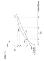
- FIG. 11 is a graph showing an exemplary nonlinear method of calculating a temperature of a gas with varying filament diameters using the gas temperature measurement system shown in FIG. 1 ;
- FIG. 12 is a graph showing an exemplary linear method of calculating a temperature of a gas with varying filament emissivities using the gas temperature measurement system shown in FIG. 1 ;
- FIG. 13 is a graph showing an exemplary nonlinear method of calculating a temperature of a gas with varying filament emissivities using the gas temperature measurement system shown in FIG. 1 ;
- FIG. 14 is a flow chart for a method generating a three-dimensional (3D) map of temperature in a volume of interest of the turbomachine shown in FIGS. 1 and 2 .
- Approximating language may be applied to modify any quantitative representation that could permissibly vary without resulting in a change in the basic function to which it is related. Accordingly, a value modified by a term or terms, such as “about” and “substantially”, are not to be limited to the precise value specified. In at least some instances, the approximating language may correspond to the precision of an instrument for measuring the value.
- range limitations may be combined and/or interchanged, such ranges are identified and include all the sub-ranges contained therein unless context or language indicates otherwise.
- the gas temperature measurement systems described herein include a method and systems of measuring gas temperatures using thin filament pyrometry that provide a cost-effective and reliable means of monitoring process parameters in heretofore difficult areas of components that experience harsh environmental conditions. As such, the gas temperature measurement systems described herein provide a cost-effective method for monitoring temperatures of components in high temperature and/or high pressure environments.
- the devices, systems, and methods described herein include temperature measuring filaments of varying diameters and/or emissivity distributed in a gas turbine engine.
- the gas temperature measurement systems described herein determine a temperature measurement for the plurality of filaments as a function of the associated diameters and/or emissivity and then correlate such temperature determinations to determine a gas temperature of the portion of the gas turbine engine associated with the filaments. Therefore, the methods and systems described herein facilitate measuring two and three dimensional temperature maps of gas turbine hot gas path components during operation.
- the gas temperature measurement systems described herein facilitate calibrating the temperature sensors and generating accurate temperature indications without using radiation correction factors.
- FIG. 1 is a schematic view of an industrial facility 100 that includes a turbomachine, and more specifically, a gas turbine engine system 101 .
- gas turbine engine system 101 includes a gas temperature measurement system 102 .
- Gas temperature measurement system 102 may be used in any other facilities and with any other apparatus and processes that use gas temperature measurements, e.g., without limitation, power and auxiliary boilers, other turbomachinery, chemical processing plants, including, without limitation, refining plants, and solar collectors.
- gas turbine engine system 101 includes a compressor 104 and turbine 106 mounted on a common shaft 108 and coupled in a serial flow arrangement with a combustor 110 positioned between them.
- a load 112 such as, but not limited to, a generator, a pump, and a compressor is also drivingly coupled to shaft 108 .
- air or other oxygen containing working fluid is received at an air intake 114 and directed to an inlet 116 of compressor 104 , compressed air is then directed to combustor 110 , where fuel 118 is added to the flow of compressed air and ignited, generating a flow of relatively hot, high-energy gases.
- the gases are directed through turbine 106 , where work is extracted to drive compressor 104 and load 112 .
- the exhausted gases are expelled through an exhaust section 119 .
- Gas temperature measurement based on radiation thermometry using thin filaments facilitates measuring gas temperatures in hot or reacting flows in the range of approximately 500° K to approximately 2200° K with an uncertainty of approximately 50° K, a precision of approximately 1° K, a spatial resolution of approximately 50 microns, and temporal resolution of approximately 0.1 micro-sec.
- the thin-filament is typically in the range between approximately 10 microns ( ⁇ ) and approximately 5.0 millimeters (mm) in diameter.
- Thin filaments may be formed of various materials, for example, silicon-carbide (SiC), which may be selected for its good mechanical strength, modulus and fatigue strength under high temperature and pressure harsh environments, relatively constant emissivity, resistance to oxidation and catalytic effects, and wide availability.
- the filament When used for gas temperature measurements, the filament is placed in the hot gas flows and the sensor detects thermal radiation emissions from the filament. A temperature of the filament is calculated from a calibration curve (not shown in FIG. 1 ) and the gas temperature is then inferred through the energy balance between the filament, gas flow and surrounding environment. To measure gas temperature inside running gas turbines, the filament is placed in the hot gas flows, e.g., combustor, stage one nozzle (S 1 N) and stage one blade (S 1 B). Emissions from the filament are collected through view ports or windows on the gas turbine casing. A sensor detects the emissions and transforms them into digital signals. Filament temperature is calculated from the calibration curve.
- gas temperature measurement system 102 monitors one or more temperatures of the gases passing through gas turbine engine system 101 .
- Gas temperature measurement system 102 includes a plurality of filaments 120 positioned within a flow path of the hot high-energy gases generated in combustor 110 .
- filaments 120 may be positioned at for example, but not limited to, an inlet to combustor 110 , an outlet from combustor 110 , an inlet to turbine 106 , and an outlet from turbine 106 .
- Filaments 120 may also be coupled to various components operating in the gas path of gas turbine engine system 101 , such as, but not limited to, blades, vanes, cooling apertures, and stationary surfaces, e.g., nozzles, and rotatable surfaces, e.g., buckets and blades, and turbine exhausts.
- components operating in the gas path of gas turbine engine system 101 such as, but not limited to, blades, vanes, cooling apertures, and stationary surfaces, e.g., nozzles, and rotatable surfaces, e.g., buckets and blades, and turbine exhausts.
- filaments 120 are approximately 5.0 millimeters (mm) or less in diameter, e.g., without limitation, in the range between approximately 10 ⁇ and approximately 4 mm in diameter. Also, in the exemplary embodiment, filaments 120 have an emissivity within a range between approximately 0.3 and approximately 1.0. Alternatively, filaments 120 have any dimensions and emissivities that enable operation of gas temperature monitoring system 102 as described herein.
- HGP hot-gas path
- filaments 120 are configured in a plurality of portions (not shown in FIG. 1 ) such that each portion includes filaments 120 having a different diameter, a different emissivity, or a combination of both, than those filaments 120 in other portions. Using such filaments 120 with different diameters and/or emissivities improves gas temperature measurements in gas turbine engine system 101 over similar systems with filaments 120 having substantially similar diameters and emissivities.
- gas temperature measurement system 102 also includes a filament controller 122 communicatively coupled to an optical system 124 .
- Filament controller 122 is configured to control a position and/or tension of filaments 120 .
- filaments 120 may be translated across the gas path using a scanning mechanism portion (not shown separately) of filament controller 122 to obtain two-dimensional (2D) temperature profile information in the gas path or a tension of filaments 120 may be reduced to allow slack in filaments 120 .
- Such slack may permit filaments 120 to be exposed to a 2D area of the flow through the gas path permitting 2D determination of a temperature profile in the gas path.
- filament controller 122 is not used, for example, in an application where filaments 120 are fixed in position and at a constant tension.
- optical system 124 includes sufficient collection optics, i.e., optical system 124 includes an optical component 126 fabricated of a material that is at least partially transparent to thermal radiation emitted by filaments 120 to collect the thermal radiation light from thin filaments 120 .
- Optical component 126 is any device that enables operation of optical system 124 and gas temperature measurement system 102 , including, without limitation, windows, lens, and mirrors.
- Optical system 124 also includes a wavelength splitting device 128 that is configured to split broad wavelength band thermal radiation signals into a plurality of relatively narrow band thermal radiation signals.
- Optical system 124 further includes at least one detector array 130 that is configured to convert the relatively narrow band thermal radiation signals to digital signals.
- gas temperature measurement system 102 includes a controller 132 that includes a processor 134 and a memory 136 .
- Memory 136 includes one or more predetermined algorithms configured, when executed by processor 134 to convert the digital signals into temperature indication based on a predetermined calibration curve.
- processor refers to central processing units, microprocessors, microcontrollers, reduced instruction set circuits (RISC), application specific integrated circuits (ASIC), field programmable gate arrays (FPGAs), logic circuits, and any other circuit or processor capable of executing the functions described herein.
- RISC reduced instruction set circuits
- ASIC application specific integrated circuits
- FPGA field programmable gate arrays
- the terms “software” and “firmware” are interchangeable, and include any computer program stored in memory for execution by processor 134 , including RAM memory, ROM memory, EPROM memory, EEPROM memory, and non-volatile RAM (NVRAM) memory.
- RAM memory random access memory
- ROM memory read-only memory
- EPROM memory erasable programmable read-only memory
- EEPROM memory electrically erasable programmable read-only memory
- NVRAM non-volatile RAM
- Controller 132 is programmed with sufficient instructions and algorithms to enable operation of gas temperature measurement system 102 as described herein.
- MCP multi-color pyrometry
- LSMCP linear least-squares multi-color pyrometry
- non-linear MCP non-linear MCP
- Theoretical predictions for time response, spatial resolution, and radiation corrections due to thermal radiation, spatial deviations, and temporal deviations for the gas temperature measurement technique may be given by:
- the LSMCP and non-linear MCP methods use Planck's law or Wien's law as derived from Planck's law to define a plurality of matrices (described below). Wien's law states:
- T R represents the radiance temperature of an object being monitored, in units of degrees Kelvin (° K), that is determined from the radiative intensity assuming a black-body, i.e., an emissivity ( ⁇ ) value of unity (1)
- T represents the filament temperature to be determined in units of ° K
- ⁇ represents the wavelength of the emitted thermal radiation from the object in units of nanometers (nm)
- C 2 is the second radiation constant of 1.4388*10 ⁇ 2 in units of meters-° K (m° K)
- ⁇ ( ⁇ ) represents the unitless emissivity of the object as a function of the emitted thermal radiation wavelength.
- Equation (1) The logarithmic function of emissivity as a function of wavelength, i.e., ln [ ⁇ ( ⁇ )], in equation (1) above, for thin filaments, as described herein, often exhibits a polynomial dependence on the wavelength ⁇ . Therefore, a polynomial expression with an “M ⁇ 2” order may be used to facilitate fitting the emissivity ⁇ ( ⁇ ) in equation (1) as:
- Y [ y 1 y 2 y 3 ⁇ y N ]
- ⁇ and ⁇ ⁇ X [ a 0 a 1 a 2 ⁇ a M - 1 ]
- A is a coefficient matrix of the size N*M that may be expressed as:
- equation (3) is an over-determined system.
- the LSMCP method is used to determine temperature and emissivity in a closed-form solution.
- a solution X is determined which facilitates minimizing the associated Euclidean norm ⁇ Y-AX ⁇ , i.e., L 2 norm.
- the solution X is unique since the detection wavelength bands are different.
- the values for emissivity are held constant, based on, for example, and without limitation, empirical data.
- the values for emissivity are linear, based on, for example, and without limitation, empirical data.
- the non-linear MCP method may be used to generate solutions through an iterative method.
- Use of the algorithms described above facilitates increasing the accuracy of temperature measurements by reducing the effects of contamination on optical component 126 that may affect transmission, and measuring emissivity to decrease the effects of variable emissivity on temperature measurements.
- gas temperature measurement system 102 monitors one or more temperatures of the gases passing through turbine 106 of gas turbine engine system 101 .
- gas temperature measurement system 102 may be used to measure gas temperatures associated with other portions of gas turbine engine system 101 , including, without limitation, any portion of air intake 114 , compressor 104 , combustor 110 , and exhaust section 119 .
- FIG. 2 is a side cross-sectional view of a portion of gas turbine engine system 101 in accordance with an exemplary embodiment of the present system.
- FIG. 2 illustrates using gas temperature measurement system 102 to measure gas temperature at a compressor outlet 202 , a combustor inlet 204 , a combustor exit 206 , an S 1 N location 208 , and at inter-stages 210 of turbine 106 , and inside or at the exit 212 of one or more nozzles 214 and exhaust 215 .
- gas temperature measurement system 102 can be used to measure gas temperatures in other positions of gas turbine engine system 101 not shown in FIG.
- Combustor exit 206 S 1 N location 208 , inter-stages 210 , exit 212 , nozzles 214 , and exhaust 215 define a hot-gas path 220 .
- FIG. 3 is a graphical view, i.e., a graph 300 of available substantially absorption/emission free wavelength bands that may be used with gas temperature measurement system 102 (shown in FIG. 1 ) for temperature profile measurements.
- graph 300 includes an x-axis 302 graduated in units of wavelength expressed in ⁇ m.
- Graph 300 includes a y-axis 304 graduated in units of spectral radiation/emission.
- a first trace 306 indicates an amount of thermal radiation to be expected from hot surfaces within the gas path.
- a second trace 308 indicates a maximum thermal radiation expected from absorption/emission from water (H 2 O) and carbon dioxide (CO 2 ) passing through the gas path.
- the thermal radiation emitted from filaments 120 is at least partially representative of the temperature of the filaments.
- Such radiative emissions are typically contained in a broad band of wavelengths that can be divided into expected, relatively narrower detection wavelength bands.
- the relatively narrow wavelength bands of thermal radiation include at least one of a first wavelength band extending at least partially between approximately 400 nanometers (nm) and approximately 1300 nm, a second wavelength band extending at least partially between approximately 1500 nm and approximately 1800 nm, a third wavelength band extending at least partially between approximately 2000 nm and approximately 2500 nm, and a fourth wavelength band extending at least partially between approximately 2500 nm and approximately 4200 nm.
- any wavelength band, or portion thereof, may be used that enables operation of gas temperature measurement system 102 as described herein.
- any other measurements of the received thermal radiation that facilitate temperature determinations are used to enable operation of gas temperature measurement system 102 as described herein, including, without limitation, an amplitude determination.
- FIGS. 4, 5, 6, and 7 illustrate placement configurations of filaments 120 that may be used to achieve multiple spatial line temperature distributions within the gas temperature measurement system 102 (shown in FIG. 1 ).
- FIG. 4 shows a configuration 400 of filaments 120 to determine measurements with a line pattern
- FIG. 5 shows a configuration 402 of filaments 120 to determine measurements with a grid pattern
- FIG. 6 shows a configuration 404 of filaments 120 for a field measurement by scanning the filament across the field
- FIG. 7 shows configuration 406 of filaments 120 that includes a plurality of filaments 120 inside a boundary layer 408 , i.e., proximate a surface within gas turbine engine system 101 (shown in FIGS. 1 and 2 ).
- Filaments 120 may be integrated with other filaments used for other purposes.
- each of configurations 400 , 402 , 404 , and 406 respectively, include two portions of filaments 120 , i.e., a first portion 410 and a second portion 412 .
- Each filament 120 of first portion 410 has a first filament diameter and each filament 120 of second portion 412 has a second filament diameter. The second filament diameter is greater than first filament diameter as shown with the different line weights.
- filaments 120 include any number of portions, each portion populated with any number of filaments 120 with a predetermined diameter, in any configuration that enables operation of gas temperature measurement system 102 as described herein.
- each filament 120 of first portion 410 has a first filament emissivity and each filament 120 of second portion 412 has a second filament emissivity.
- the second filament emissivity is different from the first filament emissivity.
- the second filament emissivity is substantially similar to the first filament emissivity.
- filaments 120 include any number of portions, each portion populated with any number of filaments 120 with any combination of predetermined diameters and predetermined emissivities, in any configuration that enables operation of gas temperature measurement system 102 as described herein. The differing diameters and/or emissivities of filaments 120 may be used in cooperation to enhance temperature discrimination and mapping with gas temperature measurement system 102 as described herein
- each filament is programmed into controller 132 (shown in FIG. 1 ). Also, based on testing of gas temperature measurement system 102 , the photon intensity at each filament will vary and be recorded. Such photon intensities can be corroborated in real time using visual input from a detector array (not shown) associated with optical system 124 (shown in FIG. 1 ).
- configuration 400 (only shown in FIG. 4 ) and configuration 406 (only shown in FIG. 7 ) are implemented through positioning a filament 120 of first portion of filaments 410 in close proximity with a filament 120 of second portion of filaments 412 such that they measure the temperatures in a similar predetermined spatial location.
- the ranges of distances separating filaments 410 and 412 are based on determinations of disturbance to fluid flow therethrough with established upper parameters, e.g., and without limitation, a 20% reduction in fluid flow.
- Configuration 402 (only shown in FIG. 5 ) is implemented by scanning a filament 120 of first portion of filaments 410 substantially simultaneously with a filament 120 of second portion of filaments 412 such that they measure the temperatures substantially simultaneously.
- Configuration 404 (only shown in FIG. 6 ) is implemented by positioning a plurality of filaments 120 of first portion of filaments 410 in close proximity with a plurality of filaments 120 of second portion of filaments 412 such that they define a grid pattern. Also, configuration 404 is implemented through measuring temperatures from a plurality of crisscrossing filaments 120 in each of portions 410 and 412 and subsequent correlation of the measurements.
- FIG. 8 is an illustration 600 of a plurality of filament configurations for monitoring a 2D temperature field.
- filament 120 (shown in FIG. 1 ) is coupled at each end such that a tension along a length of filament 120 is controllable.
- filament 120 is taut and traverses a substantially straight path between an upper connection point 604 and a lower connection point 606 .
- filament 120 is not taut and traverses an arcuate path between upper connection point 604 and lower connection point 606 .
- filament 120 is not taut and traverses a more arcuate path between upper connection point 604 and lower connection point 606 .
- filament 120 is not taut and traverses an even more arcuate path between upper connection point 604 and lower connection point 606 .
- Filament controller 122 (shown in FIG. 1 ) is controllable manually, through controller 132 (shown in FIG. 1 ), or through an internal algorithm to effect the changes in tension needed for each particular operating situation. The internal algorithm uses inputs of both tension and filament length available.
- FIG. 9 is a graph 700 showing exemplary calibration curves 706 , 707 , and 708 to convert the sensor signal to a temperature of filament 120 (shown in FIG. 1 ).
- Graph 700 includes a y-axis 702 representing a measured temperature divided into units of ° K extending between 800° K and 2200° K in increments of 200° K.
- Graph 700 also includes an x-axis 704 representing signal intensities divided into arbitrary intensity units extending between 0 and 1000 in increments of 200.
- the values of signal intensities plotted along x-axis 704 are at least partially based on a product of filament diameter and emissivity.
- filaments 120 may have any combination of similar diameters, different diameters, similar emissivities, and different emissivities.
- Graph 700 further includes a first calibration curve 706 for a first filament from first portion 410 (shown in FIGS. 4-7 ) having the first diameter and/or the first emissivity.
- Graph 700 also includes a second calibration curve 707 for a second filament from second portion 412 (shown in FIGS. 4-7 ) having the second diameter and/or the second emissivity.
- Graph 700 also includes a third calibration curve 708 for a third filament from a third portion (not shown) having the third diameter and/or the third emissivity.
- Curves 706 , 707 , and 708 are generated through exposing filter samples of each filament to a laminar flat flame burner used to generate an accurate temperature reference having a substantially uniform temperature distribution and well characterized temperature accuracy at the temperature range of interest for calibration of filaments 120 (shown in FIGS. 4-7 ).
- any method of calibration of filaments 120 that enables operation of gas temperature measurement system 102 as described herein is used including, without limitation, calibration with a black body or oven with a similar temperature range as the temperature range of interest.
- Determinations for temperatures as a function of filament diameters for the gas temperature measurement technique include determining:
- T g T f + ⁇ f ⁇ ⁇ h g ⁇ ( T f 4 - T ⁇ 4 ) , Eq . ⁇ ( 10 )
- T g the temperature of the gas in ° K
- T f the temperature of the filaments in ° K and is determined from calibration curves 706 and 708
- ⁇ f the unitless emissivity of the filaments
- ⁇ represents the Stefan-Boltzmann constant of 5.6704 ⁇ 10 ⁇ 8 W/(K ⁇ 4 m 2 )
- T ⁇ represents the temperature of the surrounding environment in ° K.
- h g represents the heat transfer coefficient of gas in W/(m 2 K) and may be expressed as:
- T g may be represented by:
- T g T f + ⁇ f ⁇ d f ⁇ ⁇ k f ⁇ Nu ⁇ ( T f 4 - T ⁇ 4 ) . Eq . ⁇ ( 13 )
- Equation (14) a - x b ⁇ ( x 4 - c ) , Eq . ⁇ ( 14 )
- equation (14) only needs to be solved for x and y, where a is the gas temperature T g . Therefore, to solve for the two unknowns x and y, two equations are needed.
- FIG. 10 is a graph 800 showing an exemplary linear method of calculating a temperature of a gas with varying filament diameters using gas temperature measurement system 102 (shown in FIG. 1 ).
- Graph 800 includes a y-axis 802 representing a measured filament temperature and an x-axis 804 representing diameters of the filaments.
- Graph 800 further includes a first point 806 corresponding to a first filament diameter d 1 and a first filament temperature T 1 .
- Graph 800 also includes a second point 808 corresponding to a second filament diameter d 2 and a second filament temperature T 2 .
- Graph 800 further includes a third point 810 corresponding to a third filament diameter d 3 and a third filament temperature T 3 .
- the temperatures T 1 , T 2 , and T 3 up to T n , where n is the total number of filaments used for this temperature determination, are calculated using equation (14) above.
- a substantially linear curve 812 is fitted through points 806 , 808 , and 810 such that an intersection with y-axis 802 at a point 814 is extrapolated.
- Point 814 represents the true gas temperature when the diameter of an imaginary filament is at zero. While curve 812 is shown as a straight line in the exemplary embodiment, curve 812 may have any shape that enables operation of gas temperature measurement system 102 as described herein, including, without limitation, parabolic.
- filaments 120 are approximately 5.0 millimeters (mm) or less in diameter, e.g., without limitation, in the range between approximately 10 ⁇ and approximately 4 mm in diameter.
- filaments 120 have any dimensions that enable operation of gas temperature monitoring system 102 as described herein.
- FIG. 11 is a graph 820 showing an exemplary nonlinear method of calculating a temperature of a gas with varying filament diameters using gas temperature measurement system 102 (shown in FIG. 1 ).
- Graph 820 includes a y-axis 822 representing a measured filament temperature and an x-axis 824 representing diameters of the filaments.
- Graph 820 further includes a first point 826 corresponding to a first filament diameter d 1 and a first filament temperature T 1 .
- Graph 820 also includes a second point 828 corresponding to a second filament diameter d 2 and a second filament temperature T 2 .
- Graph 820 further includes a third point 810 corresponding to a third filament diameter d 3 and a third filament temperature T 3 .
- the temperatures T 1 , T 2 , and T 3 up to T n are calculated using equation (14) above.
- a nonlinear curve 832 is fitted through points 826 , 828 , and 830 such that an intersection with y-axis 822 at a point 834 is extrapolated.
- Point 834 represents the true gas temperature when the diameter of an imaginary filament is at zero. While curve 832 is shown as a parabolic curve in the exemplary embodiment, curve 832 may have any shape that enables operation of gas temperature measurement system 102 as described herein.
- FIG. 12 is a graph 840 showing an exemplary linear method of calculating a temperature of a gas with varying filament emissivities using gas temperature measurement system 102 (shown in FIG. 1 ).
- Graph 840 includes a y-axis 842 representing a measured filament temperature and an x-axis 844 representing emissivities of the filaments.
- Graph 840 further includes a first point 846 corresponding to a first filament emissivity ⁇ 1 and a first filament temperature T 1 .
- Graph 840 also includes a second point 848 corresponding to a second filament emissivity ⁇ 2 and a second filament temperature T 2 .
- Graph 840 further includes a third point 850 corresponding to a third filament emissivity ⁇ 3 and a third filament temperature T 3 .
- the temperatures T 1 , T 2 , and T 3 up to T n , where n is the total number of filaments used for this temperature determination, are calculated using equation (14) above.
- a substantially linear curve 852 is fitted through points 846 , 848 , and 850 such that an intersection with y-axis 842 at a point 854 is extrapolated. Point 854 represents the true gas temperature when the emissivity of an imaginary filament is at zero. While curve 852 is shown as a straight line in the exemplary embodiment, curve 852 may have any shape that enables operation of gas temperature measurement system 102 as described herein, including, without limitation, parabolic.
- filaments 120 have an emissivity in the range between approximately 0.3 and approximately 1.0.
- filaments 120 have any emissivities that enable operation of gas temperature monitoring system 102 as described herein.
- FIG. 13 is a graph 860 showing an exemplary nonlinear method of calculating a temperature of a gas with varying filament emissivities using gas temperature measurement system 102 (shown in FIG. 1 ).
- Graph 860 includes a y-axis 862 representing a measured filament temperature and an x-axis 864 representing emissivities of the filaments.
- Graph 860 further includes a first point 866 corresponding to a first filament emissivity ⁇ 1 and a first filament temperature T 1 .
- Graph 860 also includes a second point 868 corresponding to a second filament emissivity ⁇ 2 and a second filament temperature T 2 .
- Graph 860 further includes a third point 870 corresponding to a third filament emissivity ⁇ 3 and a third filament temperature T 3 .
- the temperatures T 1 , T 2 , and T 3 up to T n , where n is the total number of filaments used for this temperature determination, are calculated using equation (14) above.
- a substantially nonlinear curve 872 is fitted through points 866 , 868 , and 870 such that an intersection with y-axis 862 at a point 874 is extrapolated. Point 874 represents the true gas temperature when the emissivity of an imaginary filament is at zero. While curve 872 is shown as a parabolic curve in the exemplary embodiment, curve 872 may have any shape that enables operation of gas temperature measurement system 102 as described herein.
- any combination of linear and nonlinear diameter methods with any combination of linear and nonlinear emissivity methods may be used that enables operation of gas temperature measurement system 102 as described herein.
- FIG. 14 is a flow chart for a method 900 of generating a three-dimensional (3D) map of temperature in a volume of interest.
- Method 900 includes receiving 902 continuous broad wavelength thermal radiation emitted by thin filaments 120 with different diameters and/or emissivities via optical system 124 .
- Method 900 also includes splitting 904 broad wavelength thermal radiation into multiple narrow wavelength bands via wavelength splitting device 128 .
- Method 900 further includes receiving 906 the multiple narrow wavelength bands' thermal radiation and outputting a respective intensity map via at least one detector array 130 .
- Method 900 also includes computing 908 a thin filament temperature map based upon the digital signals via numerical algorithms.
- Method 900 further includes correlating 910 the thin filament temperatures with different diameters and/or emissivities to get the true gas temperature map.
- Method 900 also includes projecting 912 the measured distributed temperature map to generate a 3D flow field of the volume of interest.
- the gas temperature measurement systems described above include a method and systems of measuring temperature using thin filament pyrometry that provide a cost-effective and reliable means of monitoring process parameters in heretofore difficult areas of components that experience harsh environmental conditions. As such, the gas temperature measurement systems described above provide a cost-effective method for monitoring temperatures of components in high temperature and/or high pressure environments.
- the devices, systems, and methods described above include temperature measuring filaments of varying diameters and/or emissivities distributed in a gas turbine engine. The devices, systems, and methods described above determine a temperature measurement for the plurality of filaments as a function of the associated diameters and/or emissivities and then correlate such temperature determinations to determine a gas temperature of the portion of the gas turbine engine associated with the filaments.
- the devices, systems, and methods described above facilitate measuring two and three dimensional temperature maps of gas turbine hot gas path components during operation.
- the devices, systems, and methods described above facilitate calibrating the temperature sensors and generating accurate temperature indications without using emissivity correction factors.
- the above-described embodiments of the disclosure may be implemented using computer programming or engineering techniques including computer software, firmware, hardware or any combination or subset thereof, wherein the technical effect is at least one of: (a) positioning one or more filaments in a flow path of a fluid; (b) splitting a continuous broadband wavelength of thermal radiation emitted by a plurality of filaments with different diameters and/or emissivities into a plurality of relatively narrow wavelength bands of thermal radiation, wherein a wavelength or amplitude of the emitted thermal radiation relates to a temperature of the filament; (c) receiving the emitted thermal radiation by a detector array; (d) generating electrical signals using the received thermal radiation; (e) computing temperature profiles based upon the digital voltage signals via numerical algorithms; (f) correlating temperatures associated with filaments with different diameters to get the true gas temperature profiles; (g) transforming the generated electrical signals to a temperature indication; and (h) mapping the measured distributed temperature profiles to generate a 3D profile.
- Any such resulting program, having computer-readable code means, may be embodied or provided within one or more computer-readable media, thereby making a computer program product, i.e., an article of manufacture, according to the discussed embodiments of the disclosure.
- the computer readable media may be, for example, but is not limited to, a fixed (hard) drive, diskette, optical disk, magnetic tape, semiconductor memory such as read-only memory (ROM), and/or any transmitting/receiving medium such as the Internet or other communication network or link.
- the article of manufacture containing the computer code may be made and/or used by executing the code directly from one medium, by copying the code from one medium to another medium, or by transmitting the code over a network.
- modules may be implemented as a hardware circuit comprising custom very large scale integration (“VLSI”) circuits or gate arrays, off-the-shelf semiconductors such as logic chips, transistors, or other discrete components.
- VLSI very large scale integration
- a module may also be implemented in programmable hardware devices such as field programmable gate arrays (FPGAs), programmable array logic, programmable logic devices (PLDs) or the like.
- Modules may also be implemented in software for execution by various types of processors.
- An identified module of executable code may, for instance, comprise one or more physical or logical blocks of computer instructions, which may, for instance, be organized as an object, procedure, or function. Nevertheless, the executables of an identified module need not be physically located together, but may comprise disparate instructions stored in different locations which, when joined logically together, comprise the module and achieve the stated purpose for the module.
- a module of executable code may be a single instruction, or many instructions, and may even be distributed over several different code segments, among different programs, and across several memory devices.
- operational data may be identified and illustrated herein within modules, and may be embodied in any suitable form and organized within any suitable type of data structure. The operational data may be collected as a single data set, or may be distributed over different locations including over different storage devices, and may exist, at least partially, merely as electronic signals on a system or network.
- gas temperature measurement systems for gas turbine engines are described above in detail.
- the gas temperature measurement systems, and methods of operating such systems are not limited to the specific embodiments described herein, but rather, components of systems and/or steps of the methods may be utilized independently and separately from other components and/or steps described herein.
- the methods may also be used in combination with other systems requiring observation of temperatures in high temperature environments, and are not limited to practice with only the gas turbine engines as described herein. Rather, the exemplary embodiment can be implemented and utilized in connection with many other high temperature applications.
Landscapes
- Physics & Mathematics (AREA)
- General Physics & Mathematics (AREA)
- Spectroscopy & Molecular Physics (AREA)
- Chemical & Material Sciences (AREA)
- Engineering & Computer Science (AREA)
- Combustion & Propulsion (AREA)
- Radiation Pyrometers (AREA)
Abstract
Description
| Quantity | Definitions | Proportional |
| τ | Time response |
|
τ ∝ d2 f |
| δ | Spatial resolution |
|
δ ∝ df |
| ΔT | Radiation correction |
|
ΔT ∝ df, |
| where |
| Symbols | ||
| cf | J/(kgK) | specific heat of filament |
| df | m | Diameter of filament |
| hg | W/(m2K) | Heat transfer coefficient of gas |
| kf | W/(mK) | Thermal conductivity of filament |
| Tf | K | Temperature of filament |
| Tg | K | Temperature of gas |
| T∞ | K | Temperature of surrounding environment |
| ΔT | K | Temperature correction [ΔT = Tg − Tf ] |
| εf | Emissivity of filament | |
| ρf | kg/m3 | Density of filament |
| σ | W/(K−4m2) | Stefan-Boltzmann constant, 5.6704 × 10⁻⁸ |
where TR represents the radiance temperature of an object being monitored, in units of degrees Kelvin (° K), that is determined from the radiative intensity assuming a black-body, i.e., an emissivity (ε) value of unity (1), T represents the filament temperature to be determined in units of ° K, λ represents the wavelength of the emitted thermal radiation from the object in units of nanometers (nm), and C2 is the second radiation constant of 1.4388*10−2 in units of meters-° K (m° K), and ε(λ) represents the unitless emissivity of the object as a function of the emitted thermal radiation wavelength. With determined values for λ, ε(λ), and TR, a temperature of the filament may be determined by using intensities measured a predetermined wavelengths in equation (1) above within
Y=A*X, Eq. (3)
where Y is a known vector of size N*1 and X is an unknown vector of size M*1 which may be expressed as:
where A is a coefficient matrix of the size N*M that may be expressed as:
where yj=−1/(TR)j at wavelength λj, and where j=1, 2, . . . , N, and a0=−1/T.
A T *Y=(A T *A)*X, Eq. (5)
where matrix AT is the transpose of the matrix A.
ln [ε(λ)]=C 2 a 1, Eq. (6)
and the solution for temperature and emissivity is:
ln [ε(λ)]=C 2(a 1 +a 2λi),where i=1,2, . . . ,N, Eq. (8)
and the solution for temperature and emissivity is:
where Tg represents the temperature of the gas in ° K, Tf represents the temperature of the filaments in ° K and is determined from
and where
Nu=CRe m Pr 0.37, Eq. (12)
where, Nu represents the kinematic viscosity in square meters per second (m2/s), C is a predetermined constant, Re represents the Reynold's number, m represents a curve fitting coefficient as a function of the Reynold's number, and Pr represents the Prndtl number. As such, Tg may be represented by:
where, if c=T∞ is known, equation (14) only needs to be solved for x and y, where a is the gas temperature Tg. Therefore, to solve for the two unknowns x and y, two equations are needed. Such equations may be provided using filaments of two different diameters and/or a thin wire with a different emissivity, i.e., two values of y=εfdf 1-m. As such, the values of y=Tf are then determined.
Claims (23)
Priority Applications (1)
| Application Number | Priority Date | Filing Date | Title |
|---|---|---|---|
| US13/969,186 US9528880B2 (en) | 2013-08-16 | 2013-08-16 | Method and system for gas temperature measurement |
Applications Claiming Priority (1)
| Application Number | Priority Date | Filing Date | Title |
|---|---|---|---|
| US13/969,186 US9528880B2 (en) | 2013-08-16 | 2013-08-16 | Method and system for gas temperature measurement |
Publications (2)
| Publication Number | Publication Date |
|---|---|
| US20150049786A1 US20150049786A1 (en) | 2015-02-19 |
| US9528880B2 true US9528880B2 (en) | 2016-12-27 |
Family
ID=52466831
Family Applications (1)
| Application Number | Title | Priority Date | Filing Date |
|---|---|---|---|
| US13/969,186 Expired - Fee Related US9528880B2 (en) | 2013-08-16 | 2013-08-16 | Method and system for gas temperature measurement |
Country Status (1)
| Country | Link |
|---|---|
| US (1) | US9528880B2 (en) |
Cited By (2)
| Publication number | Priority date | Publication date | Assignee | Title |
|---|---|---|---|---|
| US10400623B2 (en) * | 2014-05-20 | 2019-09-03 | Safran Aircraft Engines | Method for detecting a fluid leak in a turbomachine and system for distributing a fluid |
| US12487124B2 (en) | 2022-01-31 | 2025-12-02 | General Electric Company | Systems and methods for measuring temperature |
Families Citing this family (9)
| Publication number | Priority date | Publication date | Assignee | Title |
|---|---|---|---|---|
| US9335215B2 (en) * | 2012-07-31 | 2016-05-10 | General Electric Company | Method and system for gas temperature measurement |
| US9599514B2 (en) * | 2013-01-24 | 2017-03-21 | General Electric Company | Multi-color pyrometry imaging system and method of operating the same |
| US9983189B2 (en) * | 2016-02-26 | 2018-05-29 | Pratt & Whitney Canada Corp. | Detection of oil contamination in engine air |
| US10451573B2 (en) * | 2016-03-22 | 2019-10-22 | General Electric Company | Method and system for gas temperature measurement |
| US10094714B2 (en) | 2016-03-23 | 2018-10-09 | General Electric Company | Method and system for gas temperature measurement |
| CN109556749B (en) * | 2018-12-28 | 2020-08-04 | 中国特种设备检测研究院 | A high temperature flue gas contact temperature measuring device and its measuring method |
| CN110686830B (en) * | 2019-10-23 | 2021-07-13 | 中船动力有限公司 | On-line diesel engine piston ring state detection method |
| CN110686879B (en) * | 2019-10-23 | 2021-07-13 | 中船动力有限公司 | Online diesel engine cylinder sleeve state detection method |
| CN113401360B (en) * | 2021-06-16 | 2023-03-10 | 电子科技大学 | Aero-engine turbine disk temperature measuring device based on multiband optical radiation temperature measurement |
Citations (6)
| Publication number | Priority date | Publication date | Assignee | Title |
|---|---|---|---|---|
| JPH10153488A (en) | 1996-11-21 | 1998-06-09 | Sumitomo Metal Ind Ltd | Temperature measurement device for coke oven combustion chamber |
| JP2008249462A (en) | 2007-03-30 | 2008-10-16 | Mitsui Eng & Shipbuild Co Ltd | Temperature measurement method of exhaust gas from waste incinerator |
| US20090268779A1 (en) * | 2008-04-29 | 2009-10-29 | Ngk Spark Plug Co., Ltd. | Temperature sensor element and method of manufacturing the same |
| US20090285259A1 (en) * | 2008-05-14 | 2009-11-19 | General Electric Company | System and method for thermal inspection of objects |
| US20110222582A1 (en) * | 2008-08-01 | 2011-09-15 | Ramesh Subramanian | Turbine component instrumented to provide thermal measurements |
| US20110268149A1 (en) * | 2010-05-03 | 2011-11-03 | General Electric Company | System and method for compressor inlet temperature measurement |
-
2013
- 2013-08-16 US US13/969,186 patent/US9528880B2/en not_active Expired - Fee Related
Patent Citations (6)
| Publication number | Priority date | Publication date | Assignee | Title |
|---|---|---|---|---|
| JPH10153488A (en) | 1996-11-21 | 1998-06-09 | Sumitomo Metal Ind Ltd | Temperature measurement device for coke oven combustion chamber |
| JP2008249462A (en) | 2007-03-30 | 2008-10-16 | Mitsui Eng & Shipbuild Co Ltd | Temperature measurement method of exhaust gas from waste incinerator |
| US20090268779A1 (en) * | 2008-04-29 | 2009-10-29 | Ngk Spark Plug Co., Ltd. | Temperature sensor element and method of manufacturing the same |
| US20090285259A1 (en) * | 2008-05-14 | 2009-11-19 | General Electric Company | System and method for thermal inspection of objects |
| US20110222582A1 (en) * | 2008-08-01 | 2011-09-15 | Ramesh Subramanian | Turbine component instrumented to provide thermal measurements |
| US20110268149A1 (en) * | 2010-05-03 | 2011-11-03 | General Electric Company | System and method for compressor inlet temperature measurement |
Non-Patent Citations (4)
| Title |
|---|
| Jun Ji, et al., Emission Spectroscopy Based Temperature Sensor for On-Line Non-Intrusive Gas Turbine Inlet Temperature Measurement, Proceedings of JPGC'01, 2001 International Joint Power Generation Conference, 10 pages, 2001, ASME. |
| L. P. Goss, et al., Thin-Filament Pyrometry: A Novel Thermometric Technique for Combusting Flows, Transactions of the ASME, 1989, 7 pages, vol. 111, Issue 46, Systems Research Laboratories, Dayton, OH. |
| Peter B. Kuhn, et al., Soot and Thin-Filament Pyrometry Using a Color Digital Camera, Proceedings of the Combustion Institute, pp. 743-750, 2011, vol. 33, Science Direct, Elsevier. |
| Tzong H. Chen, et al., Conditional Velocity Measurements at the Base of Turbulent, Lifted Jet Flames, Systems Research Laboratories, Inc., 7 pages, 1990, AIAA/SAE/ASME/ASEE. |
Cited By (2)
| Publication number | Priority date | Publication date | Assignee | Title |
|---|---|---|---|---|
| US10400623B2 (en) * | 2014-05-20 | 2019-09-03 | Safran Aircraft Engines | Method for detecting a fluid leak in a turbomachine and system for distributing a fluid |
| US12487124B2 (en) | 2022-01-31 | 2025-12-02 | General Electric Company | Systems and methods for measuring temperature |
Also Published As
| Publication number | Publication date |
|---|---|
| US20150049786A1 (en) | 2015-02-19 |
Similar Documents
| Publication | Publication Date | Title |
|---|---|---|
| US9528880B2 (en) | Method and system for gas temperature measurement | |
| Mekhrengin et al. | Multispectral pyrometer for high temperature measurements inside combustion chamber of gas turbine engines | |
| CN106233109B (en) | Method for determining waveguide temperature of an acoustic transceiver for a gas turbine engine | |
| US9335215B2 (en) | Method and system for gas temperature measurement | |
| Lawson et al. | Direct measurements of overall effectiveness and heat flux on a film cooled test article at high temperatures and pressures | |
| Rodríguez et al. | Accelerated thermal profiling of gas turbine components using luminescent thermal history paints | |
| KR102814942B1 (en) | Test method of heat wind tunnel for infrared suppression system | |
| Kerr et al. | Optical pyrometry for gas turbine aeroengines | |
| Gao et al. | Multi-spectral temperature measurement method for gas turbine blade | |
| CN114764035B (en) | Thermal measurement system | |
| Nau et al. | Wall temperature measurements in a full-scale gas turbine combustor test rig with fiber coupled phosphor thermometry | |
| Arcangeli et al. | Correlative analysis of effusion cooling systems | |
| Ji et al. | Error of thermocouple in measuring surface temperature of blade with cooling film | |
| US20140202130A1 (en) | Multi-color pyrometry imaging system and method of operating the same | |
| Markham et al. | Aircraft engine-mounted camera system for long wavelength infrared imaging of in-service thermal barrier coated turbine blades | |
| Jung et al. | Area-based velocimetry using TDLAS for low-speed flow | |
| EP3918289B1 (en) | Temperature measuring system | |
| US10451573B2 (en) | Method and system for gas temperature measurement | |
| US10094714B2 (en) | Method and system for gas temperature measurement | |
| Eggert et al. | Development and evaluation of a high-resolution turbine pyrometer system | |
| Fukuba et al. | Experimental and Numerical Investigation of DLN combustor for A Heavy-Duty Gas Turbine | |
| Cho | Hot gas ingress through turbine rim seals: heat transfer and fluid dynamics | |
| Kirby et al. | Infrared Thermometry for Control and Monitoring of Industrial Gas Turbines | |
| Serbin et al. | Evaluation of the Thermal Condition of Marine Gas Turbine Components via Telemetric Measurements | |
| Knisely | Integration of Infrared Thermography to Measure Part-to-Part Cooling Variations on Turbine Blades |
Legal Events
| Date | Code | Title | Description |
|---|---|---|---|
| AS | Assignment |
Owner name: GENERAL ELECTRIC COMPANY, NEW YORK Free format text: ASSIGNMENT OF ASSIGNORS INTEREST;ASSIGNORS:WANG, GUANGHUA;NIRMALAN, NIRM VELUMYLUM;BUNKER, RONALD SCOTT;AND OTHERS;SIGNING DATES FROM 20130806 TO 20130816;REEL/FRAME:031028/0779 |
|
| STCF | Information on status: patent grant |
Free format text: PATENTED CASE |
|
| FEPP | Fee payment procedure |
Free format text: MAINTENANCE FEE REMINDER MAILED (ORIGINAL EVENT CODE: REM.); ENTITY STATUS OF PATENT OWNER: LARGE ENTITY |
|
| LAPS | Lapse for failure to pay maintenance fees |
Free format text: PATENT EXPIRED FOR FAILURE TO PAY MAINTENANCE FEES (ORIGINAL EVENT CODE: EXP.); ENTITY STATUS OF PATENT OWNER: LARGE ENTITY |
|
| STCH | Information on status: patent discontinuation |
Free format text: PATENT EXPIRED DUE TO NONPAYMENT OF MAINTENANCE FEES UNDER 37 CFR 1.362 |
|
| FP | Lapsed due to failure to pay maintenance fee |
Effective date: 20201227 |