US952736A - Cider-press. - Google Patents
Cider-press. Download PDFInfo
- Publication number
- US952736A US952736A US50070809A US1909500708A US952736A US 952736 A US952736 A US 952736A US 50070809 A US50070809 A US 50070809A US 1909500708 A US1909500708 A US 1909500708A US 952736 A US952736 A US 952736A
- Authority
- US
- United States
- Prior art keywords
- frame
- rollers
- hopper
- press
- roller
- Prior art date
- Legal status (The legal status is an assumption and is not a legal conclusion. Google has not performed a legal analysis and makes no representation as to the accuracy of the status listed.)
- Expired - Lifetime
Links
- 235000013399 edible fruits Nutrition 0.000 description 6
- 238000010276 construction Methods 0.000 description 5
- 235000011389 fruit/vegetable juice Nutrition 0.000 description 4
- 241001245789 Goodea atripinnis Species 0.000 description 2
- RYGMFSIKBFXOCR-UHFFFAOYSA-N Copper Chemical compound [Cu] RYGMFSIKBFXOCR-UHFFFAOYSA-N 0.000 description 1
- 241001379910 Ephemera danica Species 0.000 description 1
- 244000141359 Malus pumila Species 0.000 description 1
- 235000021016 apples Nutrition 0.000 description 1
- 235000019987 cider Nutrition 0.000 description 1
Images
Classifications
-
- B—PERFORMING OPERATIONS; TRANSPORTING
- B30—PRESSES
- B30B—PRESSES IN GENERAL
- B30B9/00—Presses specially adapted for particular purposes
- B30B9/32—Presses specially adapted for particular purposes for consolidating scrap metal or for compacting used cars
- B30B9/321—Presses specially adapted for particular purposes for consolidating scrap metal or for compacting used cars for consolidating empty containers, e.g. cans
-
- D—TEXTILES; PAPER
- D21—PAPER-MAKING; PRODUCTION OF CELLULOSE
- D21F—PAPER-MAKING MACHINES; METHODS OF PRODUCING PAPER THEREON
- D21F3/00—Press section of machines for making continuous webs of paper
- D21F3/02—Wet presses
- D21F3/0272—Wet presses in combination with suction or blowing devices
Definitions
- This invention relates to new and useful improvements in cider presses, and has for its object to provide a device of this kind which will be exceedingly simple in construction and very easily operated.
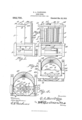
- Figure 1 is a side elevation of a press embodying my improvements.
- Fig. 2 is a top plan view thereof.
- Fig. 3, is a back View; and
- Fig. 4 is a horizontal section taken through the crushing rollers.
- the numeral 1 indicates the supporting frame, which is of approximatelyrectangular form, and is open at the front to provide for the reception of the pan or receptacle 2, for collecting the juices.
- An upright open roller supporting frame 3, comprising the top, bottom, and end pieces, 4, 5, and 6, respectively, is mounted upon the upper cross pieces 7, of the frame 1, in which is revolubly mounted a pair of corresponding vertically disposed crushing rollers 8 and 8', which intermesh with each other.
- rlhese rollers are fixedly mounted upon the shafts 9, which extend through the top and bottom pieces 4 and 5, of the frame 3, and through the bearings 10.
- the shaft of the crushing roller 8 extends below the bottom piece 5, of the frame 3, and is provided with the pulley 11, by means of which it is driven.
- the bearings for the shaft of the roller 8, are adjustably mounted upon the front faces of the ribs or flanges 12 and 13, by the bolts 14, which extend through said bearings and through longitudinal slot-s 15,
- the adjustable roller8 may be brought nearly to or farther away from the stationary roller 8, depending upon the kind of fruit which is to be crushed.
- the upper end of the roller 8 is provided with the annular flange 16, while the lower end of the adjustable roller 8 is provided with a similar flange 17, which prevents the fruit from passing out at the upper or lower ends of these rollers and causes all of the fruit to pass between the rollers.
- a flat plate 18, is mounted upon the bottom piece of the frame 3, beneath the crushing rollers to collect the juices, said plate being corrugated as shown, and provided with the discharge port 19, at the front thereof through which the juices pass or flow to the pan or receptacle 2.
- a hopper 20, closes in the frontJ side of the frame B, and covers the crushing rollers, said hopper being provided at opposite end edges with the flat portions 21, and which fit against the inner faces of the end pieces 6, of the frame 3, and have their upper edges recessed to receive the front edge of the top piece 4, of said frame.
- This hopper is also provided with a liat base 22, which is recessed at one side, as at 23, to receive the flange of the adjustable crushing roller.
- This hopper is held in removable position by the keepers 24, which are pivoted to the top piece 23, and are provided at their free end with the hooks 25, which engage apertures 26, in the hopper.
- the apples or other fruit are placed in the hopper and the crushing rollers driven by means of the pulley 11, the fruit passing between the crushing rollers and the juices being collected by the pan 18, and discharged into the receptacle 2.
- rl ⁇ he crushed fruit or pulp falls from between the rollers at the rear side.
- a suitable conveyer may be arranged to carry otll the pulp as fastas it accumulates.
- a press of the class described comprising a main supporting trame, ⁇ a secondary upright supporting 'rame mounted thereon, a pair of vertically disposed crushing rollers mounted in said upright frame, a discharge pan arranged beneath the rollers, and a ⁇ hopper removably mounted upon said vpan in front of the rollers.
- a press of the class described comprising a main supporting frame, a secondary upright supporting frame mounted thereon, a pair of vertically disposed crushing rollers mounted in said upright frame, .a discharge pan arranged beneath the rollers, a hopper removably mounted upon said pan in front of the rollers, keepers pivoted to the upright frame for holding the hopper in removable position, and means for adjusting one of the crushing rollers toward or away from the other roller.
- a device of the class described comprising a main supporting ⁇ frame, a secondary upright frame mounted thereon, a drip pan mounted in said secondary frame, a stationary 'verticallyY disposed crushing roller mounted in said upright frame above said drip pan, a second similar crushing roller adjustably mounted in said frame, a hopper mounted on the drip pan in front of the rollers, and keepers pivoted to the upright frame for holding the hopper in removable position.
Landscapes
- Engineering & Computer Science (AREA)
- Mechanical Engineering (AREA)
- Crushing And Grinding (AREA)
- Disintegrating Or Milling (AREA)
Description
G. A.. HAZBLBIGG.
GIDER PRESS.
APPLIoATIoN FILED JUNE 7, 1909.
95;?3@ Patented Mar. 22, 1910.
Smog/who@ GEORGE A. HAZELRIGG, OF WINCHESTER, ILLINOIS.
CIDER-PRESS.
Specification of Letters Patent.
Patented Mar. 22, 1910.
Application filed .Tune 7, 1909. Serial No. 560,708.
To all whom it may concern:
Be it known that I, `GEORGE A. Hazlit- Inoo, a citizen of the United States, residing at VinChester, in the county of Scott and State of illinois, have invented certain new and useful Improvements in Cider-Presses; and l do declare the following to be a full, clear, and exact description of the invention, such as will enable others skilled in the art to which it appertains to make and use the same.
This invention relates to new and useful improvements in cider presses, and has for its object to provide a device of this kind which will be exceedingly simple in construction and very easily operated.
QV ith this and other objects in view, the invention consists of certain novel features of construction, combination and arrangement of parts, as will be more fully described .and particularly pointed out in the appended claims.
In the accompanying drawings: Figure 1 is a side elevation of a press embodying my improvements. Fig. 2, is a top plan view thereof. Fig. 3, is a back View; and Fig. 4 is a horizontal section taken through the crushing rollers.
Referring to the drawings for a more particular description of the invention, the numeral 1 indicates the supporting frame, which is of approximatelyrectangular form, and is open at the front to provide for the reception of the pan or receptacle 2, for collecting the juices. An upright open roller supporting frame 3, comprising the top, bottom, and end pieces, 4, 5, and 6, respectively, is mounted upon the upper cross pieces 7, of the frame 1, in which is revolubly mounted a pair of corresponding vertically disposed crushing rollers 8 and 8', which intermesh with each other. rlhese rollers are fixedly mounted upon the shafts 9, which extend through the top and bottom pieces 4 and 5, of the frame 3, and through the bearings 10. The shaft of the crushing roller 8, extends below the bottom piece 5, of the frame 3, and is provided with the pulley 11, by means of which it is driven. The bearings for the shaft of the roller 8, are adjustably mounted upon the front faces of the ribs or flanges 12 and 13, by the bolts 14, which extend through said bearings and through longitudinal slot-s 15,
formed in said flanges. By this construction, the adjustable roller8,may be brought nearly to or farther away from the stationary roller 8, depending upon the kind of fruit which is to be crushed. The upper end of the roller 8, is provided with the annular flange 16, while the lower end of the adjustable roller 8 is provided with a similar flange 17, which prevents the fruit from passing out at the upper or lower ends of these rollers and causes all of the fruit to pass between the rollers.
A flat plate 18, is mounted upon the bottom piece of the frame 3, beneath the crushing rollers to collect the juices, said plate being corrugated as shown, and provided with the discharge port 19, at the front thereof through which the juices pass or flow to the pan or receptacle 2. A hopper 20, closes in the frontJ side of the frame B, and covers the crushing rollers, said hopper being provided at opposite end edges with the flat portions 21, and which fit against the inner faces of the end pieces 6, of the frame 3, and have their upper edges recessed to receive the front edge of the top piece 4, of said frame. This hopper is also provided with a liat base 22, which is recessed at one side, as at 23, to receive the flange of the adjustable crushing roller. This hopper is held in removable position by the keepers 24, which are pivoted to the top piece 23, and are provided at their free end with the hooks 25, which engage apertures 26, in the hopper.
In practice, the apples or other fruit are placed in the hopper and the crushing rollers driven by means of the pulley 11, the fruit passing between the crushing rollers and the juices being collected by the pan 18, and discharged into the receptacle 2. rl`he crushed fruit or pulp falls from between the rollers at the rear side. If desired, a suitable conveyer may be arranged to carry otll the pulp as fastas it accumulates.
From the foregoing description, taken in connection with the accompanying drawings, the construction and operation of the invention will be readily understood without requiring a more extended explanation.
Various changes in the form, proportion and the minor details of construction may be resorted to without departing from the principle or sacrificing any of the advantages of this invention as defined in the appended t claims.
Having, thus described my invention, what I claim is:
l. In a press of the class described, comprising a main supporting trame, `a secondary upright supporting 'rame mounted thereon, a pair of vertically disposed crushing rollers mounted in said upright frame, a discharge pan arranged beneath the rollers, and a` hopper removably mounted upon said vpan in front of the rollers.
2. In a press of the class described, comprising a main supporting frame, a secondary upright supporting frame mounted thereon, a pair of vertically disposed crushing rollers mounted in said upright frame, .a discharge pan arranged beneath the rollers, a hopper removably mounted upon said pan in front of the rollers, keepers pivoted to the upright frame for holding the hopper in removable position, and means for adjusting one of the crushing rollers toward or away from the other roller.
3. In a device of the class described, comprising a main supporting` frame, a secondary upright frame mounted thereon, a drip pan mounted in said secondary frame, a stationary 'verticallyY disposed crushing roller mounted in said upright frame above said drip pan, a second similar crushing roller adjustably mounted in said frame, a hopper mounted on the drip pan in front of the rollers, and keepers pivoted to the upright frame for holding the hopper in removable position.
In vtestimony whereof I have hereunto set my hand in presence of tivo subscribing Witnesses.
'GEORGE A. I-IAZELRIGG IVitnesses Tiro?. as DRAKE, Tiros. J. Pnms'r.
Priority Applications (1)
| Application Number | Priority Date | Filing Date | Title |
|---|---|---|---|
| US50070809A US952736A (en) | 1909-06-07 | 1909-06-07 | Cider-press. |
Applications Claiming Priority (1)
| Application Number | Priority Date | Filing Date | Title |
|---|---|---|---|
| US50070809A US952736A (en) | 1909-06-07 | 1909-06-07 | Cider-press. |
Publications (1)
| Publication Number | Publication Date |
|---|---|
| US952736A true US952736A (en) | 1910-03-22 |
Family
ID=3021145
Family Applications (1)
| Application Number | Title | Priority Date | Filing Date |
|---|---|---|---|
| US50070809A Expired - Lifetime US952736A (en) | 1909-06-07 | 1909-06-07 | Cider-press. |
Country Status (1)
| Country | Link |
|---|---|
| US (1) | US952736A (en) |
-
1909
- 1909-06-07 US US50070809A patent/US952736A/en not_active Expired - Lifetime
Similar Documents
| Publication | Publication Date | Title |
|---|---|---|
| US2554114A (en) | Shredding machine | |
| US580742A (en) | And warren | |
| US241024A (en) | Cider mill and press | |
| US1908807A (en) | Fruit juice extractor | |
| US2803410A (en) | Ice crushing device capable of producing two sizes of crushed ice, dependent upon the direction of rotation | |
| US1205052A (en) | Slicer, grater, and shredder. | |
| US1403698A (en) | Roughage grinder | |
| US348019A (en) | Cider-press | |
| US1119792A (en) | Crank and lever mechanism for vegetable-cutters. | |
| US35787A (en) | Improvement in cider-mills | |
| US2652769A (en) | Apparatus for extracting juice from citrus fruits | |
| US38682A (en) | Improvement in fruit-presses | |
| US2013900A (en) | Kitchen shredder | |
| US367865A (en) | Michael thompson | |
| US75101A (en) | willotjghby | |
| US172055A (en) | Improvement in cider mills and presses | |
| US494544A (en) | bowen | |
| US469354A (en) | Culinary grater and slicer | |
| US40767A (en) | Improvement in grain-separators | |
| US38844A (en) | Improvement in grain-separators | |
| US864832A (en) | Press. | |
| US438960A (en) | Thirds to john m | |
| US93861A (en) | deniston | |
| US923966A (en) | Feed-crusher. | |
| US544807A (en) | And philip a |