US952490A - Hay-stacker. - Google Patents
Hay-stacker. Download PDFInfo
- Publication number
- US952490A US952490A US47148209A US1909471482A US952490A US 952490 A US952490 A US 952490A US 47148209 A US47148209 A US 47148209A US 1909471482 A US1909471482 A US 1909471482A US 952490 A US952490 A US 952490A
- Authority
- US
- United States
- Prior art keywords
- clutch
- rake
- pawl
- drum
- hay
- Prior art date
- Legal status (The legal status is an assumption and is not a legal conclusion. Google has not performed a legal analysis and makes no representation as to the accuracy of the status listed.)
- Expired - Lifetime
Links
- 238000010276 construction Methods 0.000 description 2
- 241001527902 Aratus Species 0.000 description 1
- 241001466077 Salina Species 0.000 description 1
- FAPWRFPIFSIZLT-UHFFFAOYSA-M Sodium chloride Chemical compound [Na+].[Cl-] FAPWRFPIFSIZLT-UHFFFAOYSA-M 0.000 description 1
- 210000005069 ears Anatomy 0.000 description 1
- 239000011435 rock Substances 0.000 description 1
- 239000011780 sodium chloride Substances 0.000 description 1
Images
Classifications
-
- A—HUMAN NECESSITIES
- A01—AGRICULTURE; FORESTRY; ANIMAL HUSBANDRY; HUNTING; TRAPPING; FISHING
- A01D—HARVESTING; MOWING
- A01D87/00—Loaders for hay or like field crops
- A01D87/12—Loaders for sheaves, stacks or bales
- A01D87/122—Loaders for sheaves, stacks or bales for bales on the ground
Definitions
- This invention comprehends certain new and useful improvements in machines for stacking hay and the like in the field, and the invention'relates particularly to in1provc ments in that type of hay stacker such as is disclosed iu my prior patent #it-738,390, dated September 8. ltlOLand in a copending application filed December '28, 190g, Serial No. 469,588.
- These hay stackers just mentioned comprise a traveling supporting framework', a crane or rake support mounted to rock on said framework so as to raise the load, and a tilting fork carried by the crane and arranged to dump thc load upon the stack that is being formed.
- the crane is tilted to raise the fork or rake by horse power through the instrumentality of a cable secured to one end ofthe crane and a drum mounted upon the front axle of the machine which is arranged to turn with the front ground or traveling wheels, and the drum is mounted loosely upon the axle and is arranged to be engaged by a clutch operated by the driver on a seat at the rear of the machine.
- the drum is provided with a ratchet so that after the crane has been tilted to raise the load, the clutch may be thrown out and a pawl engaged with the ratchet to hold the drain stationary with the rake or fork in elevated position so that the machine can be drawn to the stack preparatory to dumping or tilting the rake.
- the present invention has for its object al1 improved construction of clutch and pawl operating mechanism, whereby both the clutch and the pawl are handled by the one lever and operated alternately thereby, the clutch being positively thrown in when the pawl is raised and the pawl being positively engaged with the ratchet wheel of the drum when the pawl is thrown out, thereby avoiding any liability of accidentally permitting the fork to fall, which would obviously cause more or less damage.
- the invention consists in certain constructions, arran ements and combinations of the parts that lgshall hereinafter fully describe and claim.
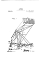
- FIG. 1 is a perspective view of a hay stacker embodying the improvements of my invention
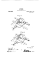
- Figs. 2 and 3 are detail perspective views on an enlarged scale of the clutch mechanism, the parts being shown in different positions in the two views.
- A designates the supporting framework of a hay stacker embodying the improvements of my invention
- B the fork or rake support
- C the tilting rake which is carried by the support.
- 1 designates the front axle of the machine which is mounted to turn with the front ground or traveling wheels
- 2 the drum which is mounted loosely on the axle and which is connected to one end of the rake support B by'means of a ⁇ cable or rope
- l the clutch which is mounted on the axle and which is designed to couple the drum 9 to the axle.
- An angular shipper-lever 5 is connected at one end to the clutch 4, said lever being fulcrumed on the front cross-beam 6 of the supporting framework A and the rear arm of said lever is pivotally connected to the front end of a rearwardly extending actuating rod 7 adapted to be manipulated by a handle lever 8 secured thereto and mounted upon the rear end of the framework in convenient roximity to the drivers seat.
- the dium 2 is provided with a ratchet wheel 9 as shown and a pawl 10, preferably spring-pressed into engagement with the ratchet 9 and which is mounted between the ears of a bracket that is secured to the crossbeam 6.
- a link-rod 11 is connected at its front end to the pawl 10, the rear end of the link-rod being screw-threaded as shown and a-djustably mounted in the upwardly extending angular end 13 of one of the straps 4111 that pivotally connect the actuating rod 7 to the rear arm of the lever 5.
- the rake may be again owered by again clutching the sleeve 4 with the drum 2 and simultaneously releasing the awl 10 from the ratchet 9 and then backing the machine the required distance, the weight of the fork assisting in this backing movement.
- a stacker the combination with a ⁇ frame-work and a rake mounted thereon, of means for raising the rake, said means in cluding an actuating axle, a drum mounted loosely thereon and provided with a ratchet wheel, a clutch adapted to secure the drum to the axle, an angular shipper lever fulcrumed on the framework and having one of its arms connected to the clutch, a pawl arranged to engage the ratchet wheel and pivotally mounted on the framework, a link rod connected at one end to the pawl, an actuating rod connected at its forward 1nd to the other arm of the shipper lever, the rear end of the link rod being connected to the actuating rod near the forward end of the latter, and a lever connected to the rear end of the actuating rod for the operation thereof.
- a stacker the combination with a framework, and a rake mounted thereon, of means for raising the rake, said means including an actuating axle, a drum mounted loosely thereon and provided with a ratchet wheel, a clutch adapted to secure the drum to the axle, a shipperdever fulcrumed on the framework and operatively connected to the clutch, an actuating rod, a awl mountcd on the framework -and designed to engage the ratchet, a link-rod connected to the said pawl and a strap connecting the actuating lod to the shipper-lever, said strap being formed with an angular end to which the rear end of the link-rod is connected.
Landscapes
- Life Sciences & Earth Sciences (AREA)
- Environmental Sciences (AREA)
- Mechanical Operated Clutches (AREA)
Description
F. WYATT.
HAY summa.
APPLICATION FILED JN.9, 19x19. 952,490. Patented Mar. 22, 1910.
2 SHEETS-SHEET 1.
` 3 munter HW @afi mma" muy:
F. WYATT.
HAY STACKER.
APPLIUATIUN FILED JAN. a, 1909,
Patented Mar. 22, 1910.
2 SHEETS-SHEET 2Y UNITED STA'S PALFENT OFFICE.
FRANK WYATT, `OF SALINA, KANSAS, ASSIGNOR T0 THE F. WYATT MANUFACTURING COMPANY, OF SALINA, KANSAS.
HAY-STACKER.
To all 'whom it 'may concern:
Be it known that l, FRANK W Ya'rr, citizen of the United States, residing at Salina, in the county of Saline and State of ,Kansas have invented certain new and useful lmprovements in Hay-Stackcrs, of which the following is a specification.
This invention comprehends certain new and useful improvements in machines for stacking hay and the like in the field, and the invention'relates particularly to in1provc ments in that type of hay stacker such as is disclosed iu my prior patent #it-738,390, dated September 8. ltlOLand in a copending application filed December '28, 190g, Serial No. 469,588. These hay stackers just mentioned comprise a traveling supporting framework', a crane or rake support mounted to rock on said framework so as to raise the load, and a tilting fork carried by the crane and arranged to dump thc load upon the stack that is being formed. The crane is tilted to raise the fork or rake by horse power through the instrumentality of a cable secured to one end ofthe crane and a drum mounted upon the front axle of the machine which is arranged to turn with the front ground or traveling wheels, and the drum is mounted loosely upon the axle and is arranged to be engaged by a clutch operated by the driver on a seat at the rear of the machine. The drum is provided with a ratchet so that after the crane has been tilted to raise the load, the clutch may be thrown out and a pawl engaged with the ratchet to hold the drain stationary with the rake or fork in elevated position so that the machine can be drawn to the stack preparatory to dumping or tilting the rake.
The present invention has for its object al1 improved construction of clutch and pawl operating mechanism, whereby both the clutch and the pawl are handled by the one lever and operated alternately thereby, the clutch being positively thrown in when the pawl is raised and the pawl being positively engaged with the ratchet wheel of the drum when the pawl is thrown out, thereby avoiding any liability of accidentally permitting the fork to fall, which would obviously cause more or less damage.
The invention consists in certain constructions, arran ements and combinations of the parts that lgshall hereinafter fully describe and claim.
Specification of Letters Patent.
Application filed January 9, 1909.
Patented Mal'. 22, 1910. serial No. 471,482.
For a full understanding of the invention, reference is to be had to the following description and accompanying drawings, in which Figure 1 is a perspective view of a hay stacker embodying the improvements of my invention, and Figs. 2 and 3 are detail perspective views on an enlarged scale of the clutch mechanism, the parts being shown in different positions in the two views.
Corresponding and like parts are referred to in the following description and indicated in all the views of the drawings by the same reference characters.
Referring to the drawings, A designates the supporting framework of a hay stacker embodying the improvements of my invention, B the fork or rake support and C the tilting rake which is carried by the support.
1 designates the front axle of the machine which is mounted to turn with the front ground or traveling wheels, 2 the drum which is mounted loosely on the axle and which is connected to one end of the rake support B by'means of a `cable or rope 3, and l the clutch which is mounted on the axle and which is designed to couple the drum 9 to the axle.
An angular shipper-lever 5 is connected at one end to the clutch 4, said lever being fulcrumed on the front cross-beam 6 of the supporting framework A and the rear arm of said lever is pivotally connected to the front end of a rearwardly extending actuating rod 7 adapted to be manipulated by a handle lever 8 secured thereto and mounted upon the rear end of the framework in convenient roximity to the drivers seat.
The dium 2 is provided with a ratchet wheel 9 as shown and a pawl 10, preferably spring-pressed into engagement with the ratchet 9 and which is mounted between the ears of a bracket that is secured to the crossbeam 6. A link-rod 11 is connected at its front end to the pawl 10, the rear end of the link-rod being screw-threaded as shown and a-djustably mounted in the upwardly extending angular end 13 of one of the straps 4111 that pivotally connect the actuating rod 7 to the rear arm of the lever 5.
From the foregoing description in connection with the accom anying drawings, it is evident that when t e operator moves the actuatin rod 7 forwardly, to swing the lever 5 in a direction to slide clutch 4 out of enga ment with the drum 2, the link-rod 11 w1 l positively swing the pawl 1Q into engagement with the ratchet 9 to hold the rum as a ainst any reverse rotation on the axle 1, an hence the rake or fork C will be positively held in an elevated position and will be prevented from falling. Both the clutch and the pawl are operated by the one hand lever and there is no chance whatever for the fork to accidentally fall.
In the practical operation of my improved hay stacker, when it is desired to elevate the rake and its load, the shipper lever 5 is elevated to clutch the sleeve 4 with the drum 2. When the rake is in its uppermost osition, the ship er lever is again operated), this time to unc utch the sleeve 4 and the drum 2 and at the same time to throw the pawl 10 against the ratchet 9. In this way the ap aratus is transported to the place where 1t is desired to deposit the load. After the load has been dum ed on the stack, the rake may be again owered by again clutching the sleeve 4 with the drum 2 and simultaneously releasing the awl 10 from the ratchet 9 and then backing the machine the required distance, the weight of the fork assisting in this backing movement.
Having thus described the invention, what is claimed as new is 1. In a stacker, the combination with a` frame-work and a rake mounted thereon, of means for raising the rake, said means in cluding an actuating axle, a drum mounted loosely thereon and provided with a ratchet wheel, a clutch adapted to secure the drum to the axle, an angular shipper lever fulcrumed on the framework and having one of its arms connected to the clutch, a pawl arranged to engage the ratchet wheel and pivotally mounted on the framework, a link rod connected at one end to the pawl, an actuating rod connected at its forward 1nd to the other arm of the shipper lever, the rear end of the link rod being connected to the actuating rod near the forward end of the latter, and a lever connected to the rear end of the actuating rod for the operation thereof.
2. In a stacker, the combination with a framework, and a rake mounted thereon, of means for raising the rake, said means including an actuating axle, a drum mounted loosely thereon and provided with a ratchet wheel, a clutch adapted to secure the drum to the axle, a shipperdever fulcrumed on the framework and operatively connected to the clutch, an actuating rod, a awl mountcd on the framework -and designed to engage the ratchet, a link-rod connected to the said pawl and a strap connecting the actuating lod to the shipper-lever, said strap being formed with an angular end to which the rear end of the link-rod is connected.
In testimony whereof I affix my signature in presence of 'two witnesses.
FRANK WYATT.
Witnesses:
It. P. CRAvENs, R. H. CRAVENS.
Priority Applications (1)
| Application Number | Priority Date | Filing Date | Title |
|---|---|---|---|
| US47148209A US952490A (en) | 1909-01-09 | 1909-01-09 | Hay-stacker. |
Applications Claiming Priority (1)
| Application Number | Priority Date | Filing Date | Title |
|---|---|---|---|
| US47148209A US952490A (en) | 1909-01-09 | 1909-01-09 | Hay-stacker. |
Publications (1)
| Publication Number | Publication Date |
|---|---|
| US952490A true US952490A (en) | 1910-03-22 |
Family
ID=3020900
Family Applications (1)
| Application Number | Title | Priority Date | Filing Date |
|---|---|---|---|
| US47148209A Expired - Lifetime US952490A (en) | 1909-01-09 | 1909-01-09 | Hay-stacker. |
Country Status (1)
| Country | Link |
|---|---|
| US (1) | US952490A (en) |
-
1909
- 1909-01-09 US US47148209A patent/US952490A/en not_active Expired - Lifetime
Similar Documents
| Publication | Publication Date | Title |
|---|---|---|
| US1359841A (en) | Truck power-shovel | |
| US2190164A (en) | Loader | |
| US1379039A (en) | Motor iioadmo-machine | |
| US1411830A (en) | Loading device for | |
| US1784558A (en) | Loading attachment for tractors | |
| US2351926A (en) | Hay rake and stacker | |
| US1725201A (en) | Loading attachment for tractors | |
| US958911A (en) | Hay-stacker. | |
| US1037632A (en) | Automatic loader. | |
| US1154493A (en) | Grain-header. | |
| US1047213A (en) | Shock and loose-grain loader. | |
| US719427A (en) | Machine for loading sand. | |
| US161221A (en) | Improvement in excavators | |
| US1007408A (en) | Shock-loader. | |
| US1450271A (en) | Haystacker | |
| US801415A (en) | Truck for handling and carrying logs. | |
| US1522423A (en) | Hay loader | |
| US417300A (en) | watkins | |
| US1087624A (en) | Hay-loader. | |
| US1045842A (en) | Manure-loader. | |
| US761710A (en) | Hay-loader. | |
| US778056A (en) | Hay rake and stacker. | |
| US489707A (en) | Wheeled excavator and carrier | |
| US907518A (en) | Loading apparatus. | |
| US800266A (en) | Stacker. |