US9523666B2 - Techniques for active passivation - Google Patents
Techniques for active passivation Download PDFInfo
- Publication number
- US9523666B2 US9523666B2 US14/570,401 US201414570401A US9523666B2 US 9523666 B2 US9523666 B2 US 9523666B2 US 201414570401 A US201414570401 A US 201414570401A US 9523666 B2 US9523666 B2 US 9523666B2
- Authority
- US
- United States
- Prior art keywords
- instrument
- passivation
- passivation species
- inlet
- species
- Prior art date
- Legal status (The legal status is an assumption and is not a legal conclusion. Google has not performed a legal analysis and makes no representation as to the accuracy of the status listed.)
- Active, expires
Links
- 238000002161 passivation Methods 0.000 title claims abstract description 132
- 238000000034 method Methods 0.000 title claims description 30
- 230000003993 interaction Effects 0.000 claims abstract description 23
- XLYOFNOQVPJJNP-UHFFFAOYSA-N water Substances O XLYOFNOQVPJJNP-UHFFFAOYSA-N 0.000 claims abstract description 18
- 238000010521 absorption reaction Methods 0.000 claims abstract description 13
- 125000000524 functional group Chemical group 0.000 claims abstract description 8
- GRYLNZFGIOXLOG-UHFFFAOYSA-N Nitric acid Chemical compound O[N+]([O-])=O GRYLNZFGIOXLOG-UHFFFAOYSA-N 0.000 claims description 51
- 229910017604 nitric acid Inorganic materials 0.000 claims description 51
- 239000002245 particle Substances 0.000 claims description 40
- QGZKDVFQNNGYKY-UHFFFAOYSA-N Ammonia Chemical compound N QGZKDVFQNNGYKY-UHFFFAOYSA-N 0.000 claims description 34
- 238000000926 separation method Methods 0.000 claims description 30
- JGTNAGYHADQMCM-UHFFFAOYSA-N perfluorobutanesulfonic acid Chemical compound OS(=O)(=O)C(F)(F)C(F)(F)C(F)(F)C(F)(F)F JGTNAGYHADQMCM-UHFFFAOYSA-N 0.000 claims description 16
- SNGREZUHAYWORS-UHFFFAOYSA-N perfluorooctanoic acid Chemical compound OC(=O)C(F)(F)C(F)(F)C(F)(F)C(F)(F)C(F)(F)C(F)(F)C(F)(F)F SNGREZUHAYWORS-UHFFFAOYSA-N 0.000 claims description 12
- 239000011253 protective coating Substances 0.000 claims description 12
- 238000001514 detection method Methods 0.000 claims description 11
- 229920001343 polytetrafluoroethylene Polymers 0.000 claims description 7
- 239000004810 polytetrafluoroethylene Substances 0.000 claims description 7
- 230000005587 bubbling Effects 0.000 claims description 4
- 150000003839 salts Chemical class 0.000 claims description 4
- HZCZXRSVKNFILZ-UHFFFAOYSA-N 2,2,3,3,4,4,5,5,6,6,7,7,8,8,8-pentadecafluorooctan-1-amine Chemical compound NCC(F)(F)C(F)(F)C(F)(F)C(F)(F)C(F)(F)C(F)(F)C(F)(F)F HZCZXRSVKNFILZ-UHFFFAOYSA-N 0.000 claims description 3
- -1 PolyTetraFluoroEthylene Polymers 0.000 claims description 3
- 229910021529 ammonia Inorganic materials 0.000 claims description 3
- 239000012528 membrane Substances 0.000 claims description 3
- JVZREVRTMWNFME-UHFFFAOYSA-N azanium;2,2,3,3,4,4,5,5,6,6,7,7,7-tridecafluoroheptanoate Chemical compound N.OC(=O)C(F)(F)C(F)(F)C(F)(F)C(F)(F)C(F)(F)C(F)(F)F JVZREVRTMWNFME-UHFFFAOYSA-N 0.000 claims 5
- 229910000069 nitrogen hydride Inorganic materials 0.000 claims 2
- SQTGBVURPMTXBT-UHFFFAOYSA-N azanium;1,1,2,2,3,3,4,4,4-nonafluorobutane-1-sulfonate Chemical compound [NH4+].[O-]S(=O)(=O)C(F)(F)C(F)(F)C(F)(F)C(F)(F)F SQTGBVURPMTXBT-UHFFFAOYSA-N 0.000 claims 1
- 230000004044 response Effects 0.000 abstract description 33
- ZWBAMYVPMDSJGQ-UHFFFAOYSA-N perfluoroheptanoic acid Chemical compound OC(=O)C(F)(F)C(F)(F)C(F)(F)C(F)(F)C(F)(F)C(F)(F)F ZWBAMYVPMDSJGQ-UHFFFAOYSA-N 0.000 description 16
- 239000003795 chemical substances by application Substances 0.000 description 15
- 238000000576 coating method Methods 0.000 description 11
- 239000011248 coating agent Substances 0.000 description 9
- 238000002347 injection Methods 0.000 description 9
- 239000007924 injection Substances 0.000 description 9
- 229920001774 Perfluoroether Polymers 0.000 description 8
- 238000010586 diagram Methods 0.000 description 6
- 239000011521 glass Substances 0.000 description 5
- 239000007788 liquid Substances 0.000 description 5
- 238000005259 measurement Methods 0.000 description 5
- WSFSSNUMVMOOMR-UHFFFAOYSA-N Formaldehyde Chemical compound O=C WSFSSNUMVMOOMR-UHFFFAOYSA-N 0.000 description 4
- 230000000694 effects Effects 0.000 description 4
- 229910000661 Mercury cadmium telluride Inorganic materials 0.000 description 3
- 239000002253 acid Substances 0.000 description 3
- 230000002378 acidificating effect Effects 0.000 description 3
- 230000015572 biosynthetic process Effects 0.000 description 3
- MCMSPRNYOJJPIZ-UHFFFAOYSA-N cadmium;mercury;tellurium Chemical compound [Cd]=[Te]=[Hg] MCMSPRNYOJJPIZ-UHFFFAOYSA-N 0.000 description 3
- 230000001419 dependent effect Effects 0.000 description 3
- 238000010494 dissociation reaction Methods 0.000 description 3
- 230000005593 dissociations Effects 0.000 description 3
- 239000007787 solid Substances 0.000 description 3
- CSCPPACGZOOCGX-UHFFFAOYSA-N Acetone Chemical compound CC(C)=O CSCPPACGZOOCGX-UHFFFAOYSA-N 0.000 description 2
- XOJVVFBFDXDTEG-UHFFFAOYSA-N Norphytane Natural products CC(C)CCCC(C)CCCC(C)CCCC(C)C XOJVVFBFDXDTEG-UHFFFAOYSA-N 0.000 description 2
- 150000007513 acids Chemical class 0.000 description 2
- 239000000443 aerosol Substances 0.000 description 2
- 230000008901 benefit Effects 0.000 description 2
- 125000003178 carboxy group Chemical group [H]OC(*)=O 0.000 description 2
- 150000001735 carboxylic acids Chemical class 0.000 description 2
- 238000006243 chemical reaction Methods 0.000 description 2
- 238000013461 design Methods 0.000 description 2
- 238000003795 desorption Methods 0.000 description 2
- 239000000428 dust Substances 0.000 description 2
- 230000006872 improvement Effects 0.000 description 2
- 238000004519 manufacturing process Methods 0.000 description 2
- 239000000463 material Substances 0.000 description 2
- 230000007246 mechanism Effects 0.000 description 2
- 230000008569 process Effects 0.000 description 2
- 239000002352 surface water Substances 0.000 description 2
- 238000011144 upstream manufacturing Methods 0.000 description 2
- 239000002699 waste material Substances 0.000 description 2
- PJDOLCGOTSNFJM-UHFFFAOYSA-N 2,2,3,3,4,4,5,5,6,6,7,7,8,8,8-pentadecafluorooctan-1-ol Chemical compound OCC(F)(F)C(F)(F)C(F)(F)C(F)(F)C(F)(F)C(F)(F)C(F)(F)F PJDOLCGOTSNFJM-UHFFFAOYSA-N 0.000 description 1
- UGMUDSKJLAUMTC-UHFFFAOYSA-N 2,2,3,3,4,4,5,5,6,6,7,7,8,8,8-pentadecafluorooctanamide Chemical compound NC(=O)C(F)(F)C(F)(F)C(F)(F)C(F)(F)C(F)(F)C(F)(F)C(F)(F)F UGMUDSKJLAUMTC-UHFFFAOYSA-N 0.000 description 1
- CCUWGJDGLACFQT-UHFFFAOYSA-N 2,2,3,3,4,4-hexafluoropentanedioic acid Chemical compound OC(=O)C(F)(F)C(F)(F)C(F)(F)C(O)=O CCUWGJDGLACFQT-UHFFFAOYSA-N 0.000 description 1
- LSNNMFCWUKXFEE-UHFFFAOYSA-M Bisulfite Chemical compound OS([O-])=O LSNNMFCWUKXFEE-UHFFFAOYSA-M 0.000 description 1
- 239000002841 Lewis acid Substances 0.000 description 1
- 239000002879 Lewis base Substances 0.000 description 1
- 229910006069 SO3H Inorganic materials 0.000 description 1
- 230000000274 adsorptive effect Effects 0.000 description 1
- 230000002776 aggregation Effects 0.000 description 1
- 238000004220 aggregation Methods 0.000 description 1
- 125000005376 alkyl siloxane group Chemical group 0.000 description 1
- 125000003368 amide group Chemical group 0.000 description 1
- 125000003277 amino group Chemical group 0.000 description 1
- 238000013459 approach Methods 0.000 description 1
- 239000012298 atmosphere Substances 0.000 description 1
- 239000005427 atmospheric aerosol Substances 0.000 description 1
- 150000001732 carboxylic acid derivatives Chemical class 0.000 description 1
- 125000002843 carboxylic acid group Chemical group 0.000 description 1
- 125000003636 chemical group Chemical group 0.000 description 1
- 238000004140 cleaning Methods 0.000 description 1
- 230000002860 competitive effect Effects 0.000 description 1
- 150000001875 compounds Chemical class 0.000 description 1
- 230000001010 compromised effect Effects 0.000 description 1
- 238000009833 condensation Methods 0.000 description 1
- 230000005494 condensation Effects 0.000 description 1
- JEGUKCSWCFPDGT-UHFFFAOYSA-N h2o hydrate Chemical compound O.O JEGUKCSWCFPDGT-UHFFFAOYSA-N 0.000 description 1
- MNWFXJYAOYHMED-UHFFFAOYSA-N heptanoic acid Chemical class CCCCCCC(O)=O MNWFXJYAOYHMED-UHFFFAOYSA-N 0.000 description 1
- 125000002887 hydroxy group Chemical group [H]O* 0.000 description 1
- 150000007517 lewis acids Chemical class 0.000 description 1
- 150000007527 lewis bases Chemical class 0.000 description 1
- 230000005923 long-lasting effect Effects 0.000 description 1
- 238000002156 mixing Methods 0.000 description 1
- 238000010899 nucleation Methods 0.000 description 1
- 230000006911 nucleation Effects 0.000 description 1
- 230000003647 oxidation Effects 0.000 description 1
- 238000007254 oxidation reaction Methods 0.000 description 1
- 238000005086 pumping Methods 0.000 description 1
- 238000011084 recovery Methods 0.000 description 1
- 230000002829 reductive effect Effects 0.000 description 1
- 238000002310 reflectometry Methods 0.000 description 1
- 238000011160 research Methods 0.000 description 1
- 230000002441 reversible effect Effects 0.000 description 1
- 238000005070 sampling Methods 0.000 description 1
- 230000035945 sensitivity Effects 0.000 description 1
- 239000002356 single layer Substances 0.000 description 1
- 239000011343 solid material Substances 0.000 description 1
- 239000002904 solvent Substances 0.000 description 1
- 150000003460 sulfonic acids Chemical class 0.000 description 1
- 239000004094 surface-active agent Substances 0.000 description 1
- 238000012360 testing method Methods 0.000 description 1
- 238000007039 two-step reaction Methods 0.000 description 1
Images


Classifications
-
- G—PHYSICS
- G01—MEASURING; TESTING
- G01N—INVESTIGATING OR ANALYSING MATERIALS BY DETERMINING THEIR CHEMICAL OR PHYSICAL PROPERTIES
- G01N33/00—Investigating or analysing materials by specific methods not covered by groups G01N1/00 - G01N31/00
- G01N33/0004—Gaseous mixtures, e.g. polluted air
- G01N33/0009—General constructional details of gas analysers, e.g. portable test equipment
- G01N33/0027—General constructional details of gas analysers, e.g. portable test equipment concerning the detector
- G01N33/0036—General constructional details of gas analysers, e.g. portable test equipment concerning the detector specially adapted to detect a particular component
- G01N33/0059—Avoiding interference of a gas with the gas to be measured
- G01N33/006—Avoiding interference of water vapour with the gas to be measured
-
- G—PHYSICS
- G01—MEASURING; TESTING
- G01J—MEASUREMENT OF INTENSITY, VELOCITY, SPECTRAL CONTENT, POLARISATION, PHASE OR PULSE CHARACTERISTICS OF INFRARED, VISIBLE OR ULTRAVIOLET LIGHT; COLORIMETRY; RADIATION PYROMETRY
- G01J3/00—Spectrometry; Spectrophotometry; Monochromators; Measuring colours
- G01J3/02—Details
- G01J3/0297—Constructional arrangements for removing other types of optical noise or for performing calibration
-
- G—PHYSICS
- G01—MEASURING; TESTING
- G01J—MEASUREMENT OF INTENSITY, VELOCITY, SPECTRAL CONTENT, POLARISATION, PHASE OR PULSE CHARACTERISTICS OF INFRARED, VISIBLE OR ULTRAVIOLET LIGHT; COLORIMETRY; RADIATION PYROMETRY
- G01J3/00—Spectrometry; Spectrophotometry; Monochromators; Measuring colours
- G01J3/02—Details
- G01J3/10—Arrangements of light sources specially adapted for spectrometry or colorimetry
- G01J3/108—Arrangements of light sources specially adapted for spectrometry or colorimetry for measurement in the infrared range
-
- G—PHYSICS
- G01—MEASURING; TESTING
- G01J—MEASUREMENT OF INTENSITY, VELOCITY, SPECTRAL CONTENT, POLARISATION, PHASE OR PULSE CHARACTERISTICS OF INFRARED, VISIBLE OR ULTRAVIOLET LIGHT; COLORIMETRY; RADIATION PYROMETRY
- G01J3/00—Spectrometry; Spectrophotometry; Monochromators; Measuring colours
- G01J3/28—Investigating the spectrum
- G01J3/42—Absorption spectrometry; Double beam spectrometry; Flicker spectrometry; Reflection spectrometry
-
- G—PHYSICS
- G01—MEASURING; TESTING
- G01N—INVESTIGATING OR ANALYSING MATERIALS BY DETERMINING THEIR CHEMICAL OR PHYSICAL PROPERTIES
- G01N33/00—Investigating or analysing materials by specific methods not covered by groups G01N1/00 - G01N31/00
- G01N33/0004—Gaseous mixtures, e.g. polluted air
- G01N33/0009—General constructional details of gas analysers, e.g. portable test equipment
- G01N33/0027—General constructional details of gas analysers, e.g. portable test equipment concerning the detector
- G01N33/0036—General constructional details of gas analysers, e.g. portable test equipment concerning the detector specially adapted to detect a particular component
- G01N33/0037—NOx
-
- G—PHYSICS
- G01—MEASURING; TESTING
- G01N—INVESTIGATING OR ANALYSING MATERIALS BY DETERMINING THEIR CHEMICAL OR PHYSICAL PROPERTIES
- G01N33/00—Investigating or analysing materials by specific methods not covered by groups G01N1/00 - G01N31/00
- G01N33/0004—Gaseous mixtures, e.g. polluted air
- G01N33/0009—General constructional details of gas analysers, e.g. portable test equipment
- G01N33/0027—General constructional details of gas analysers, e.g. portable test equipment concerning the detector
- G01N33/0036—General constructional details of gas analysers, e.g. portable test equipment concerning the detector specially adapted to detect a particular component
- G01N33/0054—Ammonia
-
- B—PERFORMING OPERATIONS; TRANSPORTING
- B01—PHYSICAL OR CHEMICAL PROCESSES OR APPARATUS IN GENERAL
- B01J—CHEMICAL OR PHYSICAL PROCESSES, e.g. CATALYSIS OR COLLOID CHEMISTRY; THEIR RELEVANT APPARATUS
- B01J19/00—Chemical, physical or physico-chemical processes in general; Their relevant apparatus
- B01J19/0006—Controlling or regulating processes
- B01J19/002—Avoiding undesirable reactions or side-effects, e.g. avoiding explosions, or improving the yield by suppressing side-reactions
-
- B—PERFORMING OPERATIONS; TRANSPORTING
- B01—PHYSICAL OR CHEMICAL PROCESSES OR APPARATUS IN GENERAL
- B01J—CHEMICAL OR PHYSICAL PROCESSES, e.g. CATALYSIS OR COLLOID CHEMISTRY; THEIR RELEVANT APPARATUS
- B01J2219/00—Chemical, physical or physico-chemical processes in general; Their relevant apparatus
- B01J2219/02—Apparatus characterised by their chemically-resistant properties
-
- C—CHEMISTRY; METALLURGY
- C12—BIOCHEMISTRY; BEER; SPIRITS; WINE; VINEGAR; MICROBIOLOGY; ENZYMOLOGY; MUTATION OR GENETIC ENGINEERING
- C12M—APPARATUS FOR ENZYMOLOGY OR MICROBIOLOGY; APPARATUS FOR CULTURING MICROORGANISMS FOR PRODUCING BIOMASS, FOR GROWING CELLS OR FOR OBTAINING FERMENTATION OR METABOLIC PRODUCTS, i.e. BIOREACTORS OR FERMENTERS
- C12M41/00—Means for regulation, monitoring, measurement or control, e.g. flow regulation
- C12M41/30—Means for regulation, monitoring, measurement or control, e.g. flow regulation of concentration
- C12M41/32—Means for regulation, monitoring, measurement or control, e.g. flow regulation of concentration of substances in solution
-
- G—PHYSICS
- G01—MEASURING; TESTING
- G01J—MEASUREMENT OF INTENSITY, VELOCITY, SPECTRAL CONTENT, POLARISATION, PHASE OR PULSE CHARACTERISTICS OF INFRARED, VISIBLE OR ULTRAVIOLET LIGHT; COLORIMETRY; RADIATION PYROMETRY
- G01J3/00—Spectrometry; Spectrophotometry; Monochromators; Measuring colours
- G01J3/02—Details
- G01J3/10—Arrangements of light sources specially adapted for spectrometry or colorimetry
- G01J2003/102—Plural sources
-
- G—PHYSICS
- G01—MEASURING; TESTING
- G01N—INVESTIGATING OR ANALYSING MATERIALS BY DETERMINING THEIR CHEMICAL OR PHYSICAL PROPERTIES
- G01N27/00—Investigating or analysing materials by the use of electric, electrochemical, or magnetic means
- G01N27/26—Investigating or analysing materials by the use of electric, electrochemical, or magnetic means by investigating electrochemical variables; by using electrolysis or electrophoresis
- G01N27/403—Cells and electrode assemblies
- G01N27/414—Ion-sensitive or chemical field-effect transistors, i.e. ISFETS or CHEMFETS
- G01N27/4141—Ion-sensitive or chemical field-effect transistors, i.e. ISFETS or CHEMFETS specially adapted for gases
-
- G—PHYSICS
- G01—MEASURING; TESTING
- G01N—INVESTIGATING OR ANALYSING MATERIALS BY DETERMINING THEIR CHEMICAL OR PHYSICAL PROPERTIES
- G01N27/00—Investigating or analysing materials by the use of electric, electrochemical, or magnetic means
- G01N27/26—Investigating or analysing materials by the use of electric, electrochemical, or magnetic means by investigating electrochemical variables; by using electrolysis or electrophoresis
- G01N27/403—Cells and electrode assemblies
- G01N27/414—Ion-sensitive or chemical field-effect transistors, i.e. ISFETS or CHEMFETS
- G01N27/4145—Ion-sensitive or chemical field-effect transistors, i.e. ISFETS or CHEMFETS specially adapted for biomolecules, e.g. gate electrode with immobilised receptors
-
- G—PHYSICS
- G01—MEASURING; TESTING
- G01N—INVESTIGATING OR ANALYSING MATERIALS BY DETERMINING THEIR CHEMICAL OR PHYSICAL PROPERTIES
- G01N33/00—Investigating or analysing materials by specific methods not covered by groups G01N1/00 - G01N31/00
- G01N33/0004—Gaseous mixtures, e.g. polluted air
- G01N33/0009—General constructional details of gas analysers, e.g. portable test equipment
- G01N33/0062—General constructional details of gas analysers, e.g. portable test equipment concerning the measuring method or the display, e.g. intermittent measurement or digital display
-
- Y—GENERAL TAGGING OF NEW TECHNOLOGICAL DEVELOPMENTS; GENERAL TAGGING OF CROSS-SECTIONAL TECHNOLOGIES SPANNING OVER SEVERAL SECTIONS OF THE IPC; TECHNICAL SUBJECTS COVERED BY FORMER USPC CROSS-REFERENCE ART COLLECTIONS [XRACs] AND DIGESTS
- Y02—TECHNOLOGIES OR APPLICATIONS FOR MITIGATION OR ADAPTATION AGAINST CLIMATE CHANGE
- Y02A—TECHNOLOGIES FOR ADAPTATION TO CLIMATE CHANGE
- Y02A50/00—TECHNOLOGIES FOR ADAPTATION TO CLIMATE CHANGE in human health protection, e.g. against extreme weather
- Y02A50/20—Air quality improvement or preservation, e.g. vehicle emission control or emission reduction by using catalytic converters
Definitions
- the present disclosure relates generally to measurement of sticky molecules, and more specifically to techniques for preventing interaction of sticky molecules with interfaces inside of an instrument.
- Nitric acid HNO 3
- NH 3 ammonia
- Other polar molecules have proven increasingly important in the understanding of atmospheric processes. Their large dipole moments and hydrophilic properties are primary factors in their nucleation and condensation roles in atmospheric aerosol formation. For example, nitric acid is an important photochemical product during NO x oxidation and is an important test of our understanding of modeled photoreactivity in the atmosphere. However, the large dipoles and hydrophilic properties of these polar molecules render them difficult to detect on timescales less than approximately 1 minute. These polar molecules may not only be “sticky” upon interfaces (i.e.
- HNO 3 and NH 3 may be considered “sticky molecules”.
- sticky molecule refers to the class of polar molecules having large dipole moments and hydrophilic properties that cause them to temporarily bind to interfaces.
- formaldehyde (CH 2 O), acetone (C 3 H 6 O), as well as other molecules that act as a Lewis acid or a Lewis base may be considered sticky molecules.
- the response time of the instrument may gradually become slower, as an increasing fraction of the interfaces becomes coated in adsorptive matter.
- One may attempt to clean the interfaces with solvents, to try to restore some of the initial benefits.
- recoating or cleaning or recoating generally involves discontinuing use of the instrument, bringing any internal vacuum to atmospheric pressure, and potentially disassembling significant portions of the instrument. Considerable instrument downtime may be incurred.
- continuous passivation may be employed to prevent interaction of sticky molecules with interfaces inside of an instrument (e.g., an infrared absorption spectrometer).
- a passivation species may be continuously applied to an inlet (e.g., a particle separation inlet) of the instrument while a sample gas stream is being applied.
- the passivation species has a highly polar functional group that strongly binds to either water or polar groups of the interface, and once bound presents a non-polar group to the gas phase in order to prevent further binding of polar molecules.
- the instrument may be actively used to detect sticky molecules while the passivation species is being applied. In this manner, a continuously renewed coating may be provided during ongoing instrument use, whose effectiveness is maintained over time.
- intermittent passivation is employed to prevent interaction of sticky molecules with interfaces inside of an instrument.
- a passivation species is applied to the inlet for a first period of time, while the sample gas stream is being applied, to build a protective coating on the interfaces.
- the passivation species is then withheld during a second period of time, during which the built protective coating continues to prevent interaction of sticky molecules with the interfaces.
- the process may be repeated in a cyclical manner to maintain sufficient coating on the interfaces to prevent interaction of sticky molecules with the interfaces. In this manner, a renewed coating may be provided that is periodically renewed during ongoing instrument use, so that its effectiveness is maintained.
- the passivation species may be selected based on the sticky molecule being detected. For example, for HNO 3 the passivation species may be selected as perfluoroheptanoic acid (PFHpA), perfluorooctanoic acid (PFOA), or perfluorobutane sulfonic acid (PFBSA), or another species. Likewise, for NH 3 the passivation species may be selected as 1H,1H-perfluorooctylamine (PFOAm) or another species. Continuous passivation or intermittent passivation may be utilized with a variety of types of inlets of the instrument, which include particle separator inlets containing, for example, a virtual impactor, a cyclone particle separator, or a PTFE membrane particle filter.
- the passivation species may be applied to the inlet of the instrument in various different manners.
- the passivation species may be introduced into a stream of air, for example, by bubbling the stream of air through a gas bubbler that contains a liquid passivation species or passing the stream of air over a solid passivation species within the gas bubbler.
- the sample gas stream may be bubbled or passed through the gas bubbler that contains the passivation species.
- the passivation species may be injected through a calibration port of the inlet.
- FIG. 1 is a diagram depicting an example instrument, configured for active (continuous or intermittent) passivation to prevent interaction of sticky molecules with interfaces inside of an instrument;
- FIG. 2A shows a graph of typical HNO 3 response time using the example instrument of FIG. 1 , absent a passivation agent;
- FIG. 2B shows a graph of example HNO 3 response time using the example instrument of FIG. 1 , with continuous application of a passivation agent (in this example, PFHpA at concentrations of approximately 1.5 ppm);
- PFHpA passivation agent
- FIG. 2C shows a graph of example measured concentration of HNO 3 upon initial injection of a passivation agent (in this example, PFHpA);
- PFHpA passivation agent
- FIG. 3A shows a graph of typical NH 3 response time using the example instrument of FIG. 1 , absent a passivation agent;
- FIG. 3B shows a graph of example NH 3 response time using the example instrument of FIG. 1 , with continuous application of a passivation agent (in this example, PFOAm at concentrations of approximately 1 ppm);
- a passivation agent in this example, PFOAm at concentrations of approximately 1 ppm
- FIG. 3C shows a graph of example measured concentration of NH 3 upon initial injection of a passivation agent (in this example, PFOAm);
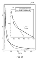
- FIG. 4 is a graph that shows example time response based upon humidity for an example implementation where the passivation species is PFHpA and the sticky molecule is HNO 3 ;
- FIG. 5 is a flow diagram of an example sequence of steps for using continuous passivation to preventing interaction of sticky molecules with interfaces inside of an instrument
- FIG. 6 is a flow diagram of an example sequence of steps for using intermittent passivation to preventing interaction of sticky molecules with interfaces inside of an instrument.
- FIG. 1 is a diagram depicting an example instrument 100 , configured for active (continuous or intermittent) passivation to prevent interaction of sticky molecules with interfaces inside of the instrument.
- the instrument 100 is an infrared absorption spectrometer having certain types of components as detailed below. However, it should be understood that the instrument 100 may alternatively be another type of instrument having different components.
- the instrument 100 may be generally divided into a detection system 110 , a particle separation inlet 120 , and a passivation species delivery system 130 .
- the detection system 110 is a dual-quantum cascade laser (QCL) detection system that provides a path length of 76 m.
- the two QCL lasers 112 , 114 may be tuned to lines pertinent to the sticky molecules being detected, for example, the 966.8 cm ⁇ 1 lines of NH 3 and the 1722.5 cm ⁇ 1 lines of HNO 3 .
- the lasers may be used with a multi-pass absorption 116 cell, of a modified astigmatic Herriot design (or another design), and a mercury cadmium telluride (MCT) detector 118 (or another type of detector).
- the absorption cell 116 may receive an incoming gas stream 129 , for example a 10 standard liter per minute (SLPM) gas stream, and exhaust gas that has already undergone analysis via a passage to a pump 140 .
- Cell pressures may be adjusted to approximately 40 Torr (or other desired pressures) by choking the pump 140 , using a ball valve, upstream pressure controller, or other similar mechanism (not shown).
- Such an arrangement may provide, for example, 1-s sensitivities of 90 parts per trillion by volume (pptv) for NH 3 and 130 pptv for HNO 3 .
- the particle separation inlet 120 coupled to the detector 110 is an inertial inlet (a form of virtual impactor).
- a sample gas stream 121 may enter via a front tip 128 , and be passed via a glass tube 122 to a critical orifice 123 .
- the glass tube 122 may include glass calibration ports 125 , 126 and an auxiliary draw 127 . After passing through the critical orifice 123 , the sample gas (and particulates) are accelerated to a higher speed at a lower pressure (approximately 100 Torr).
- the gas stream must make a turn, e.g., a 180° turn, to continue.
- the radius of this turn may be too small for aerosol and dust particles with aerodynamic diameters greater than 300 nm, which therefore pass into a waste exhaust chamber 124 .
- the waste exhaust may be approximately 1/7 of the total volume passing into the particle separation inlet 120 , creating an approximately 2 liters per minute (LPM) particle stream that is exhausted via the pump 140 .
- LPM liters per minute
- the time response of most inlets improves with increasing temperature, so here the inlet 100 may be heated and maintained, for example, to 60° C.
- PFA tubing may be used throughout the inlet 120 , and the rest of the instrument 100 .
- the particle separation inlet 120 may be a cyclone particle separator.
- the cyclone particle separator may, for example, be operated at 12.9 SLPM to provide a 0.6 ⁇ m particle separation cutpoint.
- a PFA critical orifice may be placed immediately downstream of the cyclone exit port, in order to establish critical flow.
- a PFA cross fitting may be placed upstream of the cyclone to provide a sample gas entrance port and calibration ports.
- the particle separation inlet 120 may be a PTFE-membrane particle filter.
- the filter may, for example, be operated at 12.0 SLPM, with a PFA critical orifice placed downstream to establish the flow rate. Implementations that use a cyclone or a filter may be kept at room temperature or heated.
- a passivation species delivery system 130 may be coupled to the particle separation inlet 120 .
- the passivation species delivery system 130 includes a gas bubbler that contains a liquid passivation species, through which a stream of air 131 is bubbled. If the passivation species is a solid at operating temperature, the stream of air may be passed over the solid material within the bubbler. For example, while PFBSA and PFOAm are liquids at room temperature, PFOA and PFHpA are solids.
- the gas bubbler may be located outside of the particle separation inlet 120 .
- the stream of air 131 may be between 2 and 500 standard cubic centimeters per minute (sccm) of dry, scrubbed air.
- the stream of air 131 now containing the passivation species may be entrain into the 14 SLPM sample gas stream 121 at the front tip 128 of the particle separation inlet 120 .
- the passivation species delivery system 130 may produce a desired concentration level of passivation species in the particle separation inlet 120 .
- the concentration level may be the order of 0.005 to 400 parts per million (PPM), with the exact concentration level selected based upon the passivation species employed.
- the passivation species may be selected based on the sticky molecule being detected.
- the passivation species be an acidic agent that has both an ability to eject HNO 3 from an interface, and an ability to inhibit further binding of the HNO 3 using a non-polar capping group.
- PFHpA, PFOA, or PFBSA, or another species may be selected as the passivation species for HNO 3 to provide these properties.
- the passivation species may be applied to achieve a concentration level on the order of 0.5-5 ppm in the particle separation inlet 120 .
- the passivation species may be applied to achieve a concentration level on the order of 0.05-0.5 ppm passivation in the particle separation inlet 120 .
- HNO 3 ejection behavior may be nearly universal, for example, to carboxylic acids but only certain carboxylic acids may exhibit improved response time. If, for example, non-perfluorinated heptanoic acid is used as the passivation species, some ejection may be observed, but HNO 3 response time may not be improved. The perfluorination may be important for improving response time. Further, if perfluoroglutaric acid is used as the passivation species, some ejection may be observed, but HNO 3 response time may be slightly increased, leading to a worse result. A non-polar CF 3 capping group may therefore be important for improving response time.
- a variety of other molecules with highly polar functional groups may not exhibit the same behavior as carboylic or sulfonic acids, and therefore may be unsuited for use as a passivation species for HNO 3 .
- hydroxyl and amide groups are also polar, with the latter being much more so than a carboxylic acid group (approximately 3.7 Debyes (D) vs. approximately 1.4-1.7 D, respectively).
- D deximately 3.7 Debyes (D) vs. approximately 1.4-1.7 D, respectively.
- neither perfluorooctanol nor perfluorooctanamide may eject HNO 3 or reduce response times.
- One source of this difference may rest in the solubility of the —COOH and ⁇ SO 3 H groups vs.
- the passivation species be a perfluorinated compound with a basic functional group.
- PFOAm or another species may be selected as the passivation species for NH 3
- the basic amine group of PFOAm does not react with NH 3 , yet can provide a surface passivation effect similar to the —COOH group of PFHpA.
- the passivation species may be applied to achieve a concentration level on the order of 1-30 ppm in the particle separation inlet 120
- a passivation species may significantly improve response time of an output signal produced by a detector (e.g., MCT detector 118 ) to rapid changes in concentration. For example, in some cases, application of a passivation agent may decrease response time by more than a factor of 30 over operation without a passivation species.
- FIG. 2A shows a graph 210 of typical HNO 3 response time using the example instrument 100 of FIG. 1 , absent a passivation agent.
- the example instrument 100 absent application of a passivation species may be capable of seeing HNO 3 signals changing on the timescale of minutes. It may, however, be incapable of taking eddy covariance or taking plume transect-based measurements. Coating the particle separation inlet 120 with perfluorinated siloxanes in order to provide a non-stick interface may reduce the response time somewhat in the short term. However, as discussed above, the advantages of a coating are lost as dust, aerosols, or salts condense on the interfaces over time.
- FIG. 2B shows a graph 230 of example HNO 3 response time using the example instrument 100 of FIG. 1 , with continuous application of a passivation agent (in this example, PFHpA at concentrations of approximately 1.5 ppm).
- PFHpA passivation agent
- a similar improvement in response time may be observed when passivating with PFBSA.
- PFBSA it may be desirable to maintain concentrations below approximately 100 ppb, as above such level the reflectivity of the mirrors of the multi-pass absorption cell 116 may slowly decrease, indicating the formation of a non-reflective coating.
- FIG. 2C shows a graph 250 of example measured concentration of HNO 3 upon initial injection of a passivation agent (in this example, PFHpA).
- PFHpA passivation agent
- the HNO 3 signal rapidly increases to several hundred ppb before decaying down to its original level on a timescale of minutes.
- the insert 260 present a logarithmic scale emphasizing the double exponential nature of the decay. This same HNO 3 response may be observed when applying PFHpA or PFBSA.
- the passivation species is displacing a significant amount of adsorbed HNO 3 .
- the qualitative character of the response is consistent with a two-step reaction sequence:
- FIG. 3A shows a graph 310 of typical NH 3 response time using the example instrument 100 of FIG. 1 , absent a passivation agent.
- FIG. 3B shows a graph 330 of example NH 3 response time using the example instrument 100 of FIG. 1 , with continuous application of a passivation agent (in this example, PFOAm at concentrations of approximately 1 ppm).
- a passivation agent in this example, PFOAm at concentrations of approximately 1 ppm.
- PFOAm a passivation agent
- FIG. 3C shows a graph 350 of example measured concentration of NH 3 upon initial injection of a passivation agent (in this example, PFOAm). Approximately 15 ppm of PFOAm is applied at 10 s. The insert 360 present a logarithmic scale emphasizing the double exponential nature of the decay.
- PFOAm passivation agent
- salt formation can occur, which may be observed as a film on the walls of the inlet.
- an acidic passivation species such as PFHpA or PFBSA
- PFHpA or PFBSA an acidic passivation species
- PFBSA a low vapor pressure NH 4 + /PFHpA ⁇ or NH 4 + /PFHSA ⁇ salt
- the protective coating may allow for continued fast response time for hours or days after passivation species application has been stopped.
- Active (continuous or intermittent) passivation may provide improved performance that is largely independent of humidity, in contrast to one-time PTFE or PFA surface coatings, where the response may be highly dependent upon relative humidity.
- the passivation species may not only eject sticky molecules at the interface, but may also eject water, or mitigate the effects of water, at the interface.
- the passivation species may mitigate the effect of water by binding to surface water molecules, for example, with a highly polar acid group, to prevent them from solvating the sticky molecule.
- FIG. 4 is a graph 400 that shows example time response based upon humidity for an example implementation where the passivation species is PFHpA and the sticky molecule is HNO 3 .
- the error bars shown on each data point may correspond to a standard deviation of the mean over greater than 10 measurements of each data point. As can be seen 75% and 90% HNO 3 recovery times are largely independent of the humidity.
- FIG. 5 is a flow diagram of an example sequence of steps 500 for using continuous passivation to preventing interaction of sticky molecules with interfaces inside of an instrument (e.g., an infrared absorption spectrometer) 100 .
- a sample gas stream including the sticky molecules e.g. HNO 3 , NH 3 , etc.
- a particle separation inlet 120 of the instrument 100 is applied to a sample gas stream including the sticky molecules.
- a passivation species e.g., PFHpA, PFOA, PFBSA or another species in the case of HNO 3 , PFOAm or another species in the case of NH 3 , or yet another species in the case of other sticky molecules
- the passivation species may have a polar functional group that binds to either water or polar groups of the interfaces, and once bound presents a non-polar group to prevent further binding of polar molecules.
- the passivation species may be applied in various ways.
- the passivation species may be introduced into a stream of air, for example by bubbling or passing the stream of air through a gas bubbler that contains the passivation species, and the stream of air may be entrained into the sample gas stream.
- the sample gas stream may be bubbled or passed through a gas bubbler that contains the passivation species.
- the passivation species may be injected through a calibration port of the particle separation inlet 120 .
- the instrument 100 is used to detect the sticky molecules.
- FIG. 6 is a flow diagram of an example sequence of steps 600 for using intermittent passivation to preventing interaction of sticky molecules with interfaces inside of an instrument (e.g., an infrared absorption spectrometer).
- a sample gas stream including the sticky molecules e.g. HNO 3 , NH 3 , etc.
- a particle separation inlet 120 of the instrument 100 is applied to a particle separation inlet 120 of the instrument 100 .
- a passivation species e.g., PFHpA, PFOA, PFBSA or another species in the case of HNO 3 , PFOAm or another species in the case of NH 3 , or yet another species in the case of other sticky molecules
- PFHpA, PFOA, PFBSA or another species in the case of HNO 3 , PFOAm or another species in the case of NH 3 , or yet another species in the case of other sticky molecules is intermittently applied to the particle separation inlet 120 , with the passivation species repeatedly applied for a first period of time (e.g., one or more hours or days) to build a protective coating on interfaces, and then withheld during a second period of time (e.g., one or more hours or days), during which the built protective coating continues to prevent interaction of sticky molecules with the interfaces.
- the instrument is used to detect the sticky molecules.
- the examples embodiments utilizing active (continuous or intermittent) passivation discussed above may be used to prevent interaction of sticky molecules with interfaces inside of an instrument. Where the instrument is used to detect the sticky molecules, improve response time when may be achieved. It should be understood that various aspects of the embodiments may be modified, added to, removed, or otherwise changed depending on the implementation. While the instrument 100 shown in FIG. 1 , includes a detection system 130 including a multi-pass absorption cell 116 used to detect the sticky molecules, it should be understood that the techniques may be used with other types of instruments and equipment, that may be used for other purposes, and which may use another type of detection system 130 , or may lack a detection system entirely. Further, while the instrument 100 shown in FIG. 1 includes a particle separation inlet 120 , it should be understood that the techniques may be used with other types of inlets, which may not perform a particle separation function. In general, it should be understood that the above descriptions are meant to be taken only by way of example.
Landscapes
- Physics & Mathematics (AREA)
- Chemical & Material Sciences (AREA)
- Spectroscopy & Molecular Physics (AREA)
- Engineering & Computer Science (AREA)
- Health & Medical Sciences (AREA)
- Life Sciences & Earth Sciences (AREA)
- General Physics & Mathematics (AREA)
- Analytical Chemistry (AREA)
- Medicinal Chemistry (AREA)
- Biochemistry (AREA)
- General Health & Medical Sciences (AREA)
- Food Science & Technology (AREA)
- Immunology (AREA)
- Pathology (AREA)
- Combustion & Propulsion (AREA)
- Investigating Or Analysing Materials By Optical Means (AREA)
- Sampling And Sample Adjustment (AREA)
- Investigating Or Analysing Materials By The Use Of Chemical Reactions (AREA)
Abstract
Description
Where subscripts ad, g, and rem correspond to HNO3 in the surface adsorbed state, the gas phase, and the removed (pumped out) state, respectively. In principle there is a reverse reaction,
but given the fast pumping speed of the system and large passivation concentration (approximatelyl ppm), the forward reaction dominates. The very rapid rise time in
Claims (23)
Priority Applications (1)
| Application Number | Priority Date | Filing Date | Title |
|---|---|---|---|
| US14/570,401 US9523666B2 (en) | 2014-12-15 | 2014-12-15 | Techniques for active passivation |
Applications Claiming Priority (1)
| Application Number | Priority Date | Filing Date | Title |
|---|---|---|---|
| US14/570,401 US9523666B2 (en) | 2014-12-15 | 2014-12-15 | Techniques for active passivation |
Publications (2)
| Publication Number | Publication Date |
|---|---|
| US20160169852A1 US20160169852A1 (en) | 2016-06-16 |
| US9523666B2 true US9523666B2 (en) | 2016-12-20 |
Family
ID=56110912
Family Applications (1)
| Application Number | Title | Priority Date | Filing Date |
|---|---|---|---|
| US14/570,401 Active 2035-07-14 US9523666B2 (en) | 2014-12-15 | 2014-12-15 | Techniques for active passivation |
Country Status (1)
| Country | Link |
|---|---|
| US (1) | US9523666B2 (en) |
Families Citing this family (1)
| Publication number | Priority date | Publication date | Assignee | Title |
|---|---|---|---|---|
| EP3821505A4 (en) * | 2018-07-13 | 2022-07-06 | The Government of the United States of America as represented by the Secretary of the Navy | HIGHLY STABLE SEMICONDUCTOR SENSORS AND LASERS FOR PHOTONIC INTEGRATED CIRCUITS ON III-V AND ON SILICON |
Citations (2)
| Publication number | Priority date | Publication date | Assignee | Title |
|---|---|---|---|---|
| US20070086915A1 (en) * | 2005-10-14 | 2007-04-19 | General Electric Company | Detection apparatus and associated method |
| US20150020577A1 (en) * | 2012-01-30 | 2015-01-22 | King Abdullah University Of Science And Technology | Gas sensor |
-
2014
- 2014-12-15 US US14/570,401 patent/US9523666B2/en active Active
Patent Citations (2)
| Publication number | Priority date | Publication date | Assignee | Title |
|---|---|---|---|---|
| US20070086915A1 (en) * | 2005-10-14 | 2007-04-19 | General Electric Company | Detection apparatus and associated method |
| US20150020577A1 (en) * | 2012-01-30 | 2015-01-22 | King Abdullah University Of Science And Technology | Gas sensor |
Non-Patent Citations (6)
| Title |
|---|
| Ellis, R.A. et al., "Characterizing a Quantum Cascade Tunable Infrared Laser Differential Absorption Spectrometer (QC-TILDAS) for measurements of atmospheric ammonia", Atmospheric Measurement Techniques, 3, pp. 397-406, Mar. 30, 2010. |
| Lee, B.H. et al., "Simultaneous measurements of atmospheric HONO and NO2 via absorption spectroscopy using tunable mid-infrared continuous-wave quantum cascade lasers", Applied Physics B, vol. 102, Issue 2, pp. 417-423, Oct. 20, 2010. |
| McManus, J.B. et al., "Astigmatic mirror multipass absorption cells for long-path-length spectroscopy", Applied Optics, vol. 34, No. 18, pp. 3336-3348, Jun. 20, 1995. |
| Neuman, J.A. et al., "Study of Inlet Materials for Sampling Atmospheric Nitric Acid", Environmental Science and Technology, vol. 33, No. 7, pp. 1133-1136, Feb. 13, 1999. |
| Ulman, Abraham, "Formation and Structure of Self-Assembled Monolayers", Chemical Reviews, vol. 96, No. 4, pp. 1533-1554, Apr. 18, 1996. |
| Xue, Chao-Hua et al., "Large-area fabrication of superhydrophobic surfaces for practical applications: an overview", Science and Technology of Advanced Materials, vol. 11, No. 3, 16 pages, Jun. 2010. |
Also Published As
| Publication number | Publication date |
|---|---|
| US20160169852A1 (en) | 2016-06-16 |
Similar Documents
| Publication | Publication Date | Title |
|---|---|---|
| Shiraiwa et al. | Kinetic multi-layer model of gas-particle interactions in aerosols and clouds (KM-GAP): linking condensation, evaporation and chemical reactions of organics, oxidants and water | |
| Hu et al. | Reaction probabilities for N2O5 hydrolysis on sulfuric acid and ammonium sulfate aerosols at room temperature | |
| Thornton et al. | N2O5 reaction on submicron sea salt aerosol: Kinetics, products, and the effect of surface active organics | |
| Heaton et al. | Composition domains in monoterpene secondary organic aerosol | |
| Borduas et al. | Gas phase oxidation of monoethanolamine (MEA) with OH radical and ozone: kinetics, products, and particles | |
| Roscioli et al. | New approaches to measuring sticky molecules: improvement of instrumental response times using active passivation | |
| CN107271254A (en) | Substances of interest is detected using gas Chemical properties of solid phas | |
| Bianchi et al. | On-line determination of ammonia at low pptv mixing ratios in the CLOUD chamber | |
| Park et al. | The inhibition of N2O5 hydrolysis in sulfuric acid by 1-butanol and 1-hexanol surfactant coatings | |
| Zhao et al. | Heterogeneous reactions of gaseous hydrogen peroxide on pristine and acidic gas-processed calcium carbonate particles: Effects of relative humidity and surface coverage of coating | |
| Stockwell et al. | Characterization of a catalyst-based conversion technique to measure total particulate nitrogen and organic carbon and comparison to a particle mass measurement instrument | |
| Oldridge et al. | Formation of gas-phase bromine from interaction of ozone with frozen and liquid NaCl/NaBr solutions: Quantitative separation of surficial chemistry from bulk-phase reaction | |
| Sobyra et al. | Production of Br2 from N2O5 and Br–in salty and surfactant-coated water microjets | |
| EP3042175B1 (en) | Liquid-free sample traps and analytical method for measuring trace level acidic and basic amc | |
| Fujita et al. | Impact of the aerosol particle included in actual flue gas on amine mist formation/growth in the post-combustion capture pilot plant | |
| Hanson et al. | The NH3 mass accommodation coefficient for uptake onto sulfuric acid solutions | |
| US9523666B2 (en) | Techniques for active passivation | |
| Robinson et al. | Heterogeneous uptake of HCl by sulfuric acid solutions | |
| Hou et al. | Deprotonated dicarboxylic acid homodimers: Hydrogen bonds and atmospheric implications | |
| Chen et al. | Uptake of gaseous alkylamides by suspended sulfuric acid particles: Formation of ammonium/aminium salts | |
| Zheng et al. | Atmospheric pressure-ion drift chemical ionization mass spectrometry for detection of trace gas species | |
| Tian et al. | Reactive uptake of monoethanolamine by sulfuric acid particles and hygroscopicity of monoethanolaminium salts | |
| Bianchini et al. | Collision-Energy Dependence of the Uptake of Hydroxyl Radicals at Atmospherically Relevant Liquid Surfaces | |
| Pouvesle et al. | The interaction of H 2 O 2 with ice surfaces between 203 and 233 K | |
| CN114544281A (en) | Methods for the determination of cesium and its compounds in workplace air |
Legal Events
| Date | Code | Title | Description |
|---|---|---|---|
| AS | Assignment |
Owner name: AERODYNE RESEARCH, INC., MASSACHUSETTS Free format text: ASSIGNMENT OF ASSIGNORS INTEREST;ASSIGNORS:ROSCIOLI, JOSEPH R.;HERNDON, SCOTT C.;NELSON, DAVID D., JR.;REEL/FRAME:034508/0292 Effective date: 20141212 |
|
| AS | Assignment |
Owner name: ENERGY, UNITED STATES DEPARTMENT OF, DISTRICT OF C Free format text: CONFIRMATORY LICENSE;ASSIGNOR:AERODYNE RESEARCH, INC.;REEL/FRAME:038990/0460 Effective date: 20160420 |
|
| STCF | Information on status: patent grant |
Free format text: PATENTED CASE |
|
| MAFP | Maintenance fee payment |
Free format text: PAYMENT OF MAINTENANCE FEE, 4TH YR, SMALL ENTITY (ORIGINAL EVENT CODE: M2551); ENTITY STATUS OF PATENT OWNER: SMALL ENTITY Year of fee payment: 4 |
|
| MAFP | Maintenance fee payment |
Free format text: PAYMENT OF MAINTENANCE FEE, 8TH YR, SMALL ENTITY (ORIGINAL EVENT CODE: M2552); ENTITY STATUS OF PATENT OWNER: SMALL ENTITY Year of fee payment: 8 |