US9522657B2 - Apparatus and method for controlling electronic parking brake - Google Patents
Apparatus and method for controlling electronic parking brake Download PDFInfo
- Publication number
- US9522657B2 US9522657B2 US15/009,787 US201615009787A US9522657B2 US 9522657 B2 US9522657 B2 US 9522657B2 US 201615009787 A US201615009787 A US 201615009787A US 9522657 B2 US9522657 B2 US 9522657B2
- Authority
- US
- United States
- Prior art keywords
- wheel pulse
- counting signals
- signals
- driver
- terminal device
- Prior art date
- Legal status (The legal status is an assumption and is not a legal conclusion. Google has not performed a legal analysis and makes no representation as to the accuracy of the status listed.)
- Active
Links
Images


Classifications
-
- B—PERFORMING OPERATIONS; TRANSPORTING
- B60—VEHICLES IN GENERAL
- B60W—CONJOINT CONTROL OF VEHICLE SUB-UNITS OF DIFFERENT TYPE OR DIFFERENT FUNCTION; CONTROL SYSTEMS SPECIALLY ADAPTED FOR HYBRID VEHICLES; ROAD VEHICLE DRIVE CONTROL SYSTEMS FOR PURPOSES NOT RELATED TO THE CONTROL OF A PARTICULAR SUB-UNIT
- B60W30/00—Purposes of road vehicle drive control systems not related to the control of a particular sub-unit, e.g. of systems using conjoint control of vehicle sub-units
- B60W30/06—Automatic manoeuvring for parking
-
- B—PERFORMING OPERATIONS; TRANSPORTING
- B60—VEHICLES IN GENERAL
- B60T—VEHICLE BRAKE CONTROL SYSTEMS OR PARTS THEREOF; BRAKE CONTROL SYSTEMS OR PARTS THEREOF, IN GENERAL; ARRANGEMENT OF BRAKING ELEMENTS ON VEHICLES IN GENERAL; PORTABLE DEVICES FOR PREVENTING UNWANTED MOVEMENT OF VEHICLES; VEHICLE MODIFICATIONS TO FACILITATE COOLING OF BRAKES
- B60T7/00—Brake-action initiating means
- B60T7/12—Brake-action initiating means for automatic initiation; for initiation not subject to will of driver or passenger
-
- B—PERFORMING OPERATIONS; TRANSPORTING
- B60—VEHICLES IN GENERAL
- B60T—VEHICLE BRAKE CONTROL SYSTEMS OR PARTS THEREOF; BRAKE CONTROL SYSTEMS OR PARTS THEREOF, IN GENERAL; ARRANGEMENT OF BRAKING ELEMENTS ON VEHICLES IN GENERAL; PORTABLE DEVICES FOR PREVENTING UNWANTED MOVEMENT OF VEHICLES; VEHICLE MODIFICATIONS TO FACILITATE COOLING OF BRAKES
- B60T13/00—Transmitting braking action from initiating means to ultimate brake actuator with power assistance or drive; Brake systems incorporating such transmitting means, e.g. air-pressure brake systems
- B60T13/74—Transmitting braking action from initiating means to ultimate brake actuator with power assistance or drive; Brake systems incorporating such transmitting means, e.g. air-pressure brake systems with electrical assistance or drive
-
- B—PERFORMING OPERATIONS; TRANSPORTING
- B60—VEHICLES IN GENERAL
- B60T—VEHICLE BRAKE CONTROL SYSTEMS OR PARTS THEREOF; BRAKE CONTROL SYSTEMS OR PARTS THEREOF, IN GENERAL; ARRANGEMENT OF BRAKING ELEMENTS ON VEHICLES IN GENERAL; PORTABLE DEVICES FOR PREVENTING UNWANTED MOVEMENT OF VEHICLES; VEHICLE MODIFICATIONS TO FACILITATE COOLING OF BRAKES
- B60T8/00—Arrangements for adjusting wheel-braking force to meet varying vehicular or ground-surface conditions, e.g. limiting or varying distribution of braking force
- B60T8/17—Using electrical or electronic regulation means to control braking
- B60T8/171—Detecting parameters used in the regulation; Measuring values used in the regulation
-
- B—PERFORMING OPERATIONS; TRANSPORTING
- B60—VEHICLES IN GENERAL
- B60T—VEHICLE BRAKE CONTROL SYSTEMS OR PARTS THEREOF; BRAKE CONTROL SYSTEMS OR PARTS THEREOF, IN GENERAL; ARRANGEMENT OF BRAKING ELEMENTS ON VEHICLES IN GENERAL; PORTABLE DEVICES FOR PREVENTING UNWANTED MOVEMENT OF VEHICLES; VEHICLE MODIFICATIONS TO FACILITATE COOLING OF BRAKES
- B60T7/00—Brake-action initiating means
- B60T7/12—Brake-action initiating means for automatic initiation; for initiation not subject to will of driver or passenger
- B60T7/122—Brake-action initiating means for automatic initiation; for initiation not subject to will of driver or passenger for locking of reverse movement
-
- B—PERFORMING OPERATIONS; TRANSPORTING
- B60—VEHICLES IN GENERAL
- B60W—CONJOINT CONTROL OF VEHICLE SUB-UNITS OF DIFFERENT TYPE OR DIFFERENT FUNCTION; CONTROL SYSTEMS SPECIALLY ADAPTED FOR HYBRID VEHICLES; ROAD VEHICLE DRIVE CONTROL SYSTEMS FOR PURPOSES NOT RELATED TO THE CONTROL OF A PARTICULAR SUB-UNIT
- B60W10/00—Conjoint control of vehicle sub-units of different type or different function
- B60W10/18—Conjoint control of vehicle sub-units of different type or different function including control of braking systems
- B60W10/184—Conjoint control of vehicle sub-units of different type or different function including control of braking systems with wheel brakes
- B60W10/192—Conjoint control of vehicle sub-units of different type or different function including control of braking systems with wheel brakes electric brakes
Definitions
- Embodiments of the present invention relate to an apparatus and method for controlling an electronic parking brake.
- an electronic parking brake according to the related art has been provided in such a way that, when a driver turns off starting using a driver-friendly automatic brake device, the brake operates automatically and when the driver steps on an accelerator while turning on starting, the brake is automatically released such that conveniences of parking are improved.
- an apparatus for controlling an electronic parking brake includes: a first detection unit that detects current wheel pulse counting signals when a vehicle rolls at a predetermined time interval for a predetermined time period after a parking operation for parking is clamped; a second detection unit that continuously receives the detected current wheel pulse counting signals at a predetermined time interval for a next time period after the predetermined time period and detects the continuously-cumulated current wheel pulse cumulative counting signals; a determination unit that determines whether the detected current wheel pulse counting signals are predetermined target wheel pulse counting signals or determines whether the detected current wheel pulse cumulative counting signals are predetermined target wheel pulse cumulative counting signals; a driving unit that drives the electronic parking brake so as to re-clamp the parking operation if it is determined that the current wheel pulse counting signals are the target wheel pulse counting signals or the current wheel pulse cumulative counting signals are the target wheel pulse cumulative counting signals; and a controller that transmits a first detection instruction to the first detection unit, transmits a second detection instruction to the second detection unit, transmits a determination
- the controller may further transmit a reset instruction to the second detection unit so as to reset the current wheel pulse cumulative counting signals if the current wheel pulse counting signals are the target wheel pulse counting signals.
- the controller may further transmit a reset instruction to the first detection unit so as to reset the current wheel pulse counting signals if the current wheel pulse cumulative counting signals are the target wheel pulse cumulative counting signals.
- the first detection unit may further detect the current wheel pulse counting signals in real time while a turn-on state of the controller is maintained even when starting of a vehicle is turned off.
- the second detection unit may further detect the current wheel pulse cumulative counting signals in real time while a turn-on state of the controller is maintained even when starting of a vehicle is turned off.
- the apparatus may further include a communication unit that communicates with a driver's portable mobile terminal device according to control of the controller, wherein, if the current wheel pulse counting signals are not the target wheel pulse counting signals, the communication unit may transmit communication signals to the driver's portable mobile terminal device so that the driver's portable mobile terminal device identifies that a current parking state is unstable.
- the apparatus may further include a communication unit that communicates with a driver's portable mobile terminal device according to control of the controller, wherein, if the current wheel pulse cumulative counting signals are not the target wheel pulse cumulative counting signals, the communication unit may transmit communication signals to the driver's portable mobile terminal device so that the driver's portable mobile terminal device identifies that a current parking state is unstable.
- the apparatus may further include a communication unit that communicates with a driver's portable mobile terminal device according to control of the controller, wherein, if the current wheel pulse counting signals are the target wheel pulse counting signals, the communication unit may transmit communication signals to the driver's portable mobile terminal device so that the driver's portable mobile terminal device identifies that a current situation is a situation in which the parking operation is to be re-clamped.
- a communication unit that communicates with a driver's portable mobile terminal device according to control of the controller, wherein, if the current wheel pulse counting signals are the target wheel pulse counting signals, the communication unit may transmit communication signals to the driver's portable mobile terminal device so that the driver's portable mobile terminal device identifies that a current situation is a situation in which the parking operation is to be re-clamped.
- the apparatus may further include a communication unit that communicates with a driver's portable mobile terminal device according to control of the controller, wherein, if the current wheel pulse cumulative counting signals are the target wheel pulse cumulative counting signals, the communication unit may transmit communication signals to the driver's portable mobile terminal device so that the driver's portable mobile terminal device identifies that a current situation is a situation in which the parking operation is to be re-clamped.
- a communication unit that communicates with a driver's portable mobile terminal device according to control of the controller, wherein, if the current wheel pulse cumulative counting signals are the target wheel pulse cumulative counting signals, the communication unit may transmit communication signals to the driver's portable mobile terminal device so that the driver's portable mobile terminal device identifies that a current situation is a situation in which the parking operation is to be re-clamped.
- the apparatus may further include a communication unit that communicates with a driver's portable mobile terminal device according to control of the controller, wherein the communication unit may transmit communication signals to the driver's portable mobile terminal device so that the driver's portable mobile terminal device identifies that a current parking state is stable, when the parking operation is to be re-clamped.
- the first detection unit may detect wheel pulse signals, and the second detection unit may detect signals excluding the wheel pulse signals.
- the controller may perform a plurality of re-clamping operations.
- a method of controlling an electronic parking brake includes: detecting current wheel pulse counting signals when a vehicle rolls at a predetermined time interval for a predetermined time period after a parking operation for parking is clamped, or receiving the detected current wheel pulse counting signals continuously at a predetermined time interval for a next time period after the predetermined time period and detecting the continuously-cumulated current wheel pulse cumulative counting signals; determining whether the detected current wheel pulse counting signals are predetermined target wheel pulse counting signals or determining whether the detected current wheel pulse cumulative counting signals are predetermined target wheel pulse cumulative counting signals; and if it is determined that the current wheel pulse counting signals are the target wheel pulse counting signals or the current wheel pulse cumulative counting signals are the target wheel pulse cumulative counting signals, driving the electronic parking brake so as to re-clamp the parking operation.
- the current wheel pulse cumulative counting signals may be reset if the current wheel pulse counting signals are the target wheel pulse counting signals.
- the current wheel pulse counting signals may be reset if the current wheel pulse cumulative counting signals are the target wheel pulse cumulative counting signals.
- the current wheel pulse counting signals may be further detected in real time while a turn-on state of the controller is maintained even when starting of a vehicle is turned off.
- the current wheel pulse cumulative counting signals may be further detected in real time while a turn-on state of the controller is maintained even when starting of a vehicle is turned off.
- a controller may be provided to the vehicle, and the method may further include communicating with a driver's portable mobile terminal device according to control of the controller, wherein, in the communicating operation, if the current wheel pulse counting signals are not the target wheel pulse counting signals, communication signals may be transmitted to the driver's portable mobile terminal device so that the driver's portable mobile terminal device identifies that a current parking state is unstable.
- a controller may be provided to the vehicle, and the method may further include communicating with a driver's portable mobile terminal device according to control of the controller, wherein, in the communicating operation, if the current wheel pulse cumulative counting signals are not the target wheel pulse cumulative counting signals, communication signals may be transmitted to the driver's portable mobile terminal device so that the driver's portable mobile terminal device identifies that a current parking state is unstable.
- a controller may be provided to the vehicle, and the method may further include communicating with a driver's portable mobile terminal device according to control of the controller, wherein, in the communicating operation, if the current wheel pulse counting signals are the target wheel pulse counting signals, communication signals may be transmitted to the driver's portable mobile terminal device so that the driver's portable mobile terminal device identifies that a current situation is a situation in which the parking operation is to be re-clamped.
- a controller may be provided to the vehicle, and the method may further include communicating with a driver's portable mobile terminal device according to control of the controller, wherein, in the communicating operation, if the current wheel pulse cumulative counting signals are the target wheel pulse cumulative counting signals, communication signals may be transmitted to the driver's portable mobile terminal device so that the driver's portable mobile terminal device identifies that a current situation is a situation in which the parking operation is to be re-clamped.
- a controller may be provided to the vehicle, and the method may further include communicating with a driver's portable mobile terminal device according to control of the controller, wherein, in the communicating operation, communication signals may be transmitted to the driver's portable mobile terminal device so that the driver's portable mobile terminal device identifies that a current parking state is stable, when the parking operation is to be re-clamped.
- FIG. 1 is a block diagram illustrating a state in which an apparatus for controlling an electronic parking brake in accordance with a first embodiment of the present invention is connected to the electronic parking brake;
- FIG. 2 is a block diagram illustrating the apparatus illustrated in FIG. 1 , in one example
- FIG. 3 is a view illustrating a state in which a parking operation caused by a detection operation performed by a first detection unit illustrated in FIG. 2 is re-clamped;
- FIG. 4 is a view illustrating a state in which a parking operation caused by a detection operation performed by a second detection unit illustrated in FIG. 2 is re-clamped;
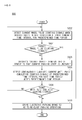
- FIG. 5 is a flowchart illustrating a method of controlling an electronic parking brake by using the apparatus for controlling an electronic parking brake in accordance with the first embodiment of the present invention, in one example;
- FIG. 6 is a block diagram illustrating a state in which an apparatus for controlling an electronic parking brake in accordance with a second embodiment of the present invention is connected to the electronic parking brake and communicates with a portable mobile terminal device;
- FIG. 7 is a block diagram illustrating the apparatus illustrated in FIG. 6 , in one example.
- FIG. 8 is a flowchart illustrating a method of controlling an electronic parking brake by using the apparatus for controlling an electronic parking brake in accordance with the second embodiment of the present invention, in one example;
- FIG. 9 is a flowchart illustrating a method of controlling an electronic parking brake by using the apparatus for controlling an electronic parking brake in accordance with the second embodiment of the present invention, in another example;
- FIG. 10 is a flowchart illustrating a method of controlling an electronic parking brake by using the apparatus for controlling an electronic parking brake in accordance with the second embodiment of the present invention, in another example;
- FIG. 11 is a flowchart illustrating a method of controlling an electronic parking brake by using the apparatus for controlling an electronic parking brake in accordance with the second embodiment of the present invention, in another example.
- FIG. 12 is a flowchart illustrating a method of controlling an electronic parking brake by using the apparatus for controlling an electronic parking brake in accordance with the second embodiment of the present invention, in another example.
- FIG. 1 is a block diagram illustrating a state in which an apparatus for controlling an electronic parking brake in accordance with a first embodiment of the present invention is connected to the electronic parking brake
- FIG. 2 is a block diagram illustrating the apparatus illustrated in FIG. 1 , in one example.
- FIG. 3 is a view illustrating a state in which a parking operation caused by a detection operation performed by a first detection unit illustrated in FIG. 2 is re-clamped
- FIG. 4 is a view illustrating a state in which a parking operation caused by a detection operation performed by a second detection unit illustrated in FIG. 2 is re-clamped.
- an apparatus 100 for controlling an electronic parking brake 10 in accordance with a first embodiment of the present invention includes a first detection unit 102 , a second detection unit 104 , a determination unit 106 , a driving unit 108 , and a controller 110 .
- the first detection unit 102 After clamping a parking operation for parking, the first detection unit 102 detects current wheel pulse counting signals WPCI- 1 through WPCI- 4 in a detection operation of the first detection unit 102 of FIGS. 3 and 4 ) when a vehicle rolls in a rear direction at a predetermined time interval (t 1 of FIGS. 3 and 4 ) for predetermined time periods (T 1 and T 2 of FIGS. 3 and 4 ).
- the first detection unit 102 may detect the current wheel pulse counting signals (WPCI- 1 through WPCI- 4 in the detection operation of the first detection unit 102 of FIGS. 3 and 4 ) while maintaining a turn-on state of the controller 110 that will be described later even when starting of the vehicle is turned off.
- the first detection unit 102 may be a wheel pulse counting sensor (not shown) for detecting the current wheel pulse counting signals (WPCI- 1 through WPCI- 4 in the detection operation of the first detection unit 102 of FIGS. 3 and 4 ) in real time.
- the first detection unit 102 may be one of all detection units for detecting current wheel pulse counting signals in real time.
- the first detection unit 102 may be one of all detection units for detecting wheel pulse counting signals in real time.
- the second detection unit 104 continuously receives the current wheel pulse counting signals (WPCI- 1 through WPCI- 4 in the detection operation of the first detection unit 102 of FIGS. 3 and 4 ) detected by the first detection unit 102 at a predetermined time interval (t 2 of FIGS. 3 and 4 ) for next time periods (T 2 and T 3 of FIGS. 3 and 4 ) after the predetermined time periods (T 1 and T 2 of FIGS. 3 and 4 ) and detects the continuously-cumulated, current wheel pulse cumulative counting signals (WPCI- 1 through WPCI- 3 in a detection operation of the second detection unit 104 of FIGS. 3 and 4 ).
- the second detection unit 104 may further detect the current wheel pulse cumulative counting signals WPCI- 1 through WPCI- 3 in the detection operation of the second detection unit 104 of FIGS. 3 and 4 ) in real time while maintaining a turn-on state of the controller 110 even when starting of the vehicle is turned off.
- the second detection unit 104 may be a wheel pulse cumulative counting sensor (not shown) for detecting the current wheel pulse cumulative counting signals (WPCI- 1 through WPCI- 3 in the detection operation of the second detection unit 104 of FIGS. 3 and 4 ) in real time.
- the second detection unit 104 may be one of all detection units for detecting the current wheel pulse cumulative counting signals in real time.
- the second detection unit 104 may be one of all detection units for detecting all signals including noise except for wheel pulse signals in real time.
- the determination unit 106 determines whether the current wheel pulse counting signals (WPCI- 1 through WPCI- 4 in the detection operation of the first detection unit 102 of FIGS. 3 and 4 ) detected by the first detection unit 102 are predetermined target wheel pulse counting signals or determines whether the current wheel pulse cumulative counting signals (WPCI- 1 through WPCI- 3 in the detection operation of the second detection unit 104 of FIGS. 3 and 4 ) detected by the second detection unit 104 are the predetermined target wheel pulse cumulative signals.
- the driving unit 108 drives the electronic parking brake 10 so as to re-clamp (A of FIG. 3 ) the parking operation, if the determination unit 106 determines that the current wheel pulse counting signal (WPCI- 4 in the detection operation of the first detection unit 102 of FIG. 3 ) is a target wheel pulse counting signal.
- the driving unit 108 may drive the electronic parking brake 10 so as to re-clamp (A of FIG. 3 ) the parking operation, if the number of times being cumulated of the current wheel pulse counting signal (WPCI- 4 in the detection operation of the first detection unit 102 of FIG. 3 ) determined by the determination unit 106 is three that is the number of times being cumulated of the target wheel pulse counting signals.
- the driving unit 108 drives the electronic parking brake 10 so as to re-clamp (A of FIG. 4 ) the parking operation, if the determination unit 106 determines that the current wheel pulse cumulative counting signals WPCI- 2 and WPCI- 3 in the detection operation of the second detection unit of FIG. 4 ) are the target wheel pulse cumulative counting signals.
- the driving unit 108 may drive the electronic parking brake 10 so as to re-clamp (A of FIG. 4 ) the parking operation, if the number of times being cumulated of the current wheel pulse counting signals (WPCI- 2 and WPCI- 3 in the detection operation of the second detection unit of FIG. 4 ) determined by the determination unit 106 is three that is the number of times being cumulated of the target wheel pulse counting signals.
- the controller 110 transmits a first detection instruction to the first detection unit 102 , transmits a second detection instruction to the second detection unit 104 , transmits a determination instruction to the determination unit 106 , and transmits a driving instruction to the driving unit 108 .
- the controller 110 may further transmit a reset instruction to the second detection unit 104 so as to reset (B of FIG. 3 ) the current wheel pulse cumulative counting signal (WPCI- 1 in the detection operation of the second detection unit of FIG. 3 ), if the determination unit 106 determines that the current wheel pulse counting signal (WPCI- 4 in the detection operation of the first detection unit 102 of FIG. 3 ) is the target wheel pulse counting signals.
- the controller 110 may further transmit the reset instruction to the second detection unit 104 so as to reset (B of FIG. 3 ) the current wheel pulse cumulative counting signal (WPCI- 1 in the detection operation of the first detection unit of FIG. 3 ), if the number of times being cumulated of the current wheel pulse counting signal (WPCI- 4 in the detection operation of the first detection unit 102 of FIG. 3 ) determined by the determination unit 106 is three that is the number of times being cumulated of the target wheel pulse counting signals.
- the controller 110 may further transmit the reset instruction to the first detection unit 102 so as to reset (B of FIG. 4 ) the current wheel pulse counting signals (WPCI- 2 and WPCI- 3 in the detection operation of the second detection unit 104 of FIG. 4 ), if the determination unit 106 determines that the current wheel pulse cumulative counting signals (WPCI- 2 and WPCI- 3 in the detection operation of the second detection unit 104 of FIG. 4 ) are the target wheel pulse cumulative counting signals.
- the controller 110 may further transmit the reset instruction to the first detection unit 102 so as to reset (B of FIG. 4 ) the current wheel pulse counting signals (WPCI- 2 and WPCI- 3 in the detection operation of the first detection unit 102 of FIG. 4 ), if the number of times being cumulated of the current wheel pulse counting signals (WPCI- 2 and WPCI- 3 in the detection operation of the second detection unit 104 of FIG. 4 ) determined by the determination unit 106 is three that is the number of times being cumulated of the target wheel pulse counting signals.
- a general electric control unit (ECU)(not shown) that controls and determines the entire operation of the vehicle and drives the electronic parking brake 10 may be provided to a main computer applied to the vehicle.
- a general micro control unit (MCU)(not shown) that controls and determines the entire operation of the vehicle and drives the electronic parking brake 10 may be provided to the main computer applied to the vehicle.
- MCU micro control unit
- the determination unit 106 , the driving unit 108 , and the controller 110 are not limited thereto, and all kinds of control units, determination units and driving units that control and determine the entire operation of the vehicle and drive the electronic parking brake 10 may be provided.
- an integrated type ECU (not shown) or MCU (not shown) having an integrated function of the determination unit 106 , the driving unit 108 and the controller 110 may be provided, or a separable ECU (not shown) or MCU (not shown) having a separated function of the determination unit, the driving unit 108 and the controller 110 may also be provided.
- a method of controlling the electronic parking brake 10 by using the apparatus 100 for controlling the electronic parking brake 10 in accordance with the first embodiment of the present invention will be described with reference to FIG. 5 .
- FIG. 5 is a flowchart illustrating a method of controlling an electronic parking brake by using the apparatus for controlling an electronic parking brake in accordance with the first embodiment of the present invention, in one example.
- a method 500 of controlling the electronic parking brake 10 by using the apparatus 100 for controlling the electronic parking brake 10 in accordance with the first embodiment of the present invention includes detection operations S 502 and S 506 , determination operations S 504 and S 508 , and a driving operation S 510 .
- the first detection unit ( 102 of FIG. 2 ) detects current wheel pulse counting signals (WPCI- 1 through WPCI- 4 in the detection operation of the first detection unit 102 of FIGS. 3 and 4 ) when the vehicle rolls in a rear direction at a predetermined time interval (t 1 of FIGS. 3 and 4 ) for predetermined time periods (T 1 and T 2 of FIGS. 3 and 4 ) according to control of the controller ( 110 of FIG. 2 ).
- WPCI- 1 through WPCI- 4 current wheel pulse counting signals
- the first detection unit ( 102 of FIG. 2 ) may further detect the current wheel pulse counting signals (WPCI- 1 through WPCI- 4 in the detection operation of the first detection unit 102 of FIGS. 3 and 4 ) in real time according to control of the controller ( 110 of FIG. 2 ).
- the determination unit ( 106 of FIG. 2 ) determines whether the current wheel pulse counting signals (WPCI- 1 through WPCI- 4 in the detection operation of the first detection unit 102 of FIGS. 3 and 4 ) detected by the first detection unit ( 102 of FIG. 2 ) are predetermined target wheel pulse counting signals, according to control of the controller ( 110 of FIG. 2 ).
- the determination unit ( 106 of FIG. 2 ) may determine whether the number of times being cumulated of the current wheel pulse counting signals (WPCI- 1 through WPCI- 4 in the detection operation of the first detection unit 102 of FIGS. 3 and 4 ) detected by the first detection unit ( 102 of FIG. 2 ) is three that is the number of times being cumulated of the target wheel pulse counting signals, according to control of the controller ( 110 of FIG. 2 ).
- the second detection unit ( 104 of FIG. 2 ) continuously receives the current wheel pulse counting signals (WPCI- 1 through WPCI- 4 in the detection operation of the first detection unit 102 of FIGS. 3 and 4 ) detected by the first detection unit ( 102 of FIG. 2 ) at a predetermined time interval (t 2 of FIGS. 3 and 4 ) for next time periods (T 2 and T 3 of FIGS. 3 and 4 ) after predetermined time periods (T 1 and T 2 of FIGS. 3 and 4 ) and detects the continuously-cumulated, current wheel pulse cumulative counting signals (WPC 1 - 1 through WPC 1 - 3 in the detection operation of the second detection unit 104 of FIGS. 3 and 4 ) according to control of the controller ( 110 of FIG. 2 ).
- the second detection unit ( 104 of FIG. 2 ) may further detect the current wheel pulse cumulative counting signals (WPCI- 1 through WPCI- 3 in the detection operation of the second detection unit 104 of FIGS. 3 and 4 ) in real time according to control of the controller ( 110 of FIG. 2 ).
- the determination unit ( 106 of FIG. 2 ) determines whether the current wheel pulse cumulative counting signals (WPCI- 1 through WPCI- 3 in the detection operation of the second detection unit 104 of FIGS. 3 and 4 ) detected by the second detection unit ( 104 of FIG. 2 ) are predetermined target wheel pulse cumulative counting signals.
- the determination unit ( 106 of FIG. 2 ) may determine whether the number of times being cumulated of the current wheel pulse counting signals (WPCI- 1 through WPCI- 3 in the detection operation of the second detection unit 104 of FIGS. 3 and 4 ) detected by the second detection unit ( 104 of FIG. 2 ) is three that is the number of times being cumulated of the target wheel pulse counting signals, according to control of the controller ( 110 of FIG. 2 ).
- the driving unit ( 108 of FIG. 2 ) drives the electronic parking brake ( 10 of FIG. 2 ) according to control of the controller ( 110 of FIG. 2 ) so as to re-clamp (A of FIG. 3 ) the parking operation.
- the driving unit ( 108 of FIG. 2 ) may drive the electronic parking brake ( 10 of FIG. 2 ) according to control of the controller ( 110 of FIG. 2 ) so as to re-clamp (A of FIG. 3 ) the parking operation.
- a reset instruction may be further transmitted to the second detection unit ( 104 of FIG. 2 ) according to control of the controller ( 110 of FIG. 2 ) so as to reset (B of FIG. 3 ) the current wheel pulse cumulative counting signal (WPCI- 1 in the detection operation of the second detection unit 104 of FIG. 3 ).
- the reset instruction may be further transmitted to the second detection unit ( 104 of FIG. 2 ) according to control of the controller ( 110 of FIG. 2 ) so as to reset (B of FIG. 3 ) the current wheel pulse cumulative counting signal (WPCI- 1 in the detection operation of the second detection unit of FIG. 3 ).
- the driving unit ( 108 of FIG. 2 ) drives the electronic parking brake ( 10 of FIG. 2 ) according to control of the controller ( 110 of FIG. 2 ) so as to re-clamp (A of FIG. 4 ) the parking operation.
- the driving unit ( 108 of FIG. 2 ) may drive the electronic parking brake ( 10 of FIG. 2 ) according to control of the controller ( 110 of FIG. 2 ) so as to re-clamp (A of FIG. 4 ) the parking operation.
- a reset instruction may be further transmitted to the first detection unit ( 102 of FIG. 2 ) according to control of the controller ( 110 of FIG. 2 ) so as to reset (B of FIG. 4 ) the current wheel pulse counting signals (WPCI- 2 and WPCI- 3 in the detection operation of the first detection unit 102 of FIG. 4 ).
- a reset instruction may be further transmitted to the first detection unit ( 102 of FIG. 2 ) according to control of the controller ( 110 of FIG. 2 ) so as to reset (B of FIG. 4 ) the current wheel pulse counting signals (WPCI- 2 and WPCI- 3 in the detection operation of the first detection unit of FIG. 4 ).
- the apparatus 100 for controlling the electronic parking brake 10 in accordance with the first embodiment of the present invention and the method 500 of controlling the electronic parking brake 10 includes the first detection unit 102 , the second detection unit 104 , the determination unit 106 , the driving unit 108 , and the controller 110 , thereby performing the detection operations S 502 and S 506 , the determination operations S 504 and S 508 , and the driving operation S 510 .
- FIG. 6 is a block diagram illustrating a state in which an apparatus for controlling an electronic parking brake in accordance with a second embodiment of the present invention is connected to the electronic parking brake and communicates with a portable mobile terminal device
- FIG. 7 is a block diagram illustrating the apparatus illustrated in FIG. 6 , in one example.
- an apparatus 600 for controlling an electronic parking brake 10 in accordance with a second embodiment of the present invention includes a first detection unit 602 , a second detection unit 604 , a determination unit 606 , a driving unit 608 , and a controller 610 , like in the apparatus ( 100 of FIGS. 1 and 2 ) for controlling the electronic parking brake ( 10 of FIGS. 1 and 2 ) in accordance with the first embodiment of the present invention.
- first detection unit 602 Since functions of the first detection unit 602 , the second detection unit 604 , the determination unit 606 , the driving unit 608 , and the controller 610 of the apparatus 600 for controlling the electronic parking brake 10 in accordance with the second embodiment of the present invention and the close connection relationship therebetween are the same as those of the first detection unit ( 102 of FIG. 2 ), the second detection unit ( 104 of FIG. 2 ), the determination unit ( 106 of FIG. 2 ), the driving unit ( 108 of FIG. 2 ), and the controller ( 110 of FIG. 2 ) of the apparatus ( 100 of FIGS. 1 and 2 ) for controlling the electronic parking brake ( 10 of FIGS. 1 and 2 ), hereinafter, detailed descriptions thereof will be omitted.
- the apparatus 600 for controlling the electronic parking brake 10 in accordance with the second embodiment of the present invention further includes a communication unit 612 .
- the communication unit 612 communicates with a driver's portable mobile terminal device 30 according to control of the controller 610 .
- the communication unit 612 may transmit communication signals to the driver's portable mobile terminal device 30 according to control of the controller 610 so that the driver's portable mobile terminal device 30 identifies that a current parking state is unstable.
- the communication unit 612 may transmit communication signals to the driver's portable mobile terminal device 30 according to control of the controller 610 so that the driver's portable mobile terminal device 30 identifies that the current parking state is unstable.
- the communication unit 612 may transmit communication signals to the driver's portable mobile terminal device 30 according to control of the controller 610 so that the driver's portable mobile terminal device 30 identifies that a current situation is a situation in which a parking operation of the electronic parking brake 10 is to be re-clamped.
- the communication unit 612 may transmit communication signals to the driver's portable mobile terminal device 30 according to control of the controller 610 so that the driver's portable mobile terminal device 30 identifies that a current situation is a situation in which the parking operation of the electronic parking brake 10 is to be re-clamped.
- the communication unit 612 may transmit communication signals to the driver's portable mobile terminal device 30 according to control of the controller 610 so that the driver's portable mobile terminal device 30 identifies that the current parking state is stable when the driving unit 608 re-clamps the parking operation of the electronic parking brake 10 .
- the communication unit 612 may communicate with the portable mobile terminal device 30 including at least one from among a wireless-fidelity (Wi-Fi) module (not shown), a Zigbee module (not shown), a wireless broadband (Wibro) module (not shown), a Wi-Max module (not shown), a long term evolution (LTE) module (not shown), and an LTE advanced module (not shown).
- Wi-Fi wireless-fidelity
- Zigbee Zigbee
- Wibro wireless broadband
- Wi-Max not shown
- LTE long term evolution
- LTE advanced module not shown
- the portable mobile terminal device 30 may be one from among a personal digital assistant (PDA)(not shown), a smartphone (not shown), a tablet personal computer (PC), a mobile phone (not shown), and a notebook (not shown).
- PDA personal digital assistant
- smartphone not shown
- PC tablet personal computer
- mobile phone not shown
- notebook not shown
- a method of controlling the electronic parking brake 10 by using the apparatus 600 for controlling the electronic parking brake 10 in accordance with the second embodiment of the present invention will be described with reference to FIGS. 8 through 12 .
- FIG. 8 is a flowchart illustrating a method of controlling an electronic parking brake by using the apparatus for controlling an electronic parking brake in accordance with the second embodiment of the present invention, in one example
- FIG. 9 is a flowchart illustrating a method of controlling an electronic parking brake by using the apparatus for controlling an electronic parking brake in accordance with the second embodiment of the present invention, in another example.
- FIG. 10 is a flowchart illustrating a method of controlling an electronic parking brake by using the apparatus for controlling an electronic parking brake in accordance with the second embodiment of the present invention, in another example
- FIG. 11 is a flowchart illustrating a method of controlling an electronic parking brake by using the apparatus for controlling an electronic parking brake in accordance with the second embodiment of the present invention, in another example.
- FIG. 12 is a flowchart illustrating a method of controlling an electronic parking brake by using the apparatus for controlling an electronic parking brake in accordance with the second embodiment of the present invention, in another example.
- methods 800 through 1200 by using the apparatus 600 for controlling the electronic parking brake 10 in accordance with the second embodiment of the present invention include detection operations S 802 through S 1202 and S 806 through S 1206 , determination operations S 804 through S 1204 and S 808 through S 1208 , and driving operations S 810 through S 1210 , like in the method ( 500 of FIG. 5 ) by using the apparatus ( 100 of FIG. 2 ) for controlling the electronic parking brake ( 10 of FIG. 2 ) in accordance with the first embodiment of the present invention.
- the methods 800 through 1200 of controlling the electronic parking brake 10 by using the apparatus 600 for controlling the electronic parking brake 10 in accordance with the second embodiment of the present invention further include communication operations S 805 , S 909 , S 1005 , S 1109 , and S 1211 .
- the communication unit ( 612 of FIG. 7 ) may communicate with the driver's portable mobile terminal device ( 30 of FIG. 7 ) according to control of the controller ( 610 of FIG. 7 ).
- the communication unit ( 612 of FIG. 7 ) may transmit communication signals to the driver's portable mobile terminal device ( 30 of FIG. 7 ) according to control of the controller ( 610 of FIG. 7 ) so that the driver's portable mobile terminal device ( 30 of FIG. 7 ) identifies that the current parking state is unstable.
- the communication unit ( 612 of FIG. 7 ) may transmit communication signals to the driver's portable mobile terminal device ( 30 of FIG. 7 ) according to control of the controller ( 610 of FIG. 7 ) so that the driver's portable mobile terminal device ( 30 of FIG. 7 ) identifies that the current parking state is unstable.
- the communication unit ( 612 of FIG. 7 ) may transmit communication signals to the driver's portable mobile terminal device ( 30 of FIG. 7 ) according to control of the controller ( 610 of FIG. 7 ) so that the driver's portable mobile terminal device ( 30 of FIG. 7 ) identifies that a current situation is a situation in which the parking operation of the electronic parking brake ( 10 of FIG. 7 ) is to be re-clamped.
- the communication unit ( 612 of FIG. 7 ) may transmit communication signals to the driver's portable mobile terminal device ( 30 of FIG. 7 ) according to control of the controller ( 610 of FIG. 7 ) so that the driver's portable mobile terminal device ( 30 of FIG. 7 ) identifies that a current situation is a situation in which the parking operation of the electronic parking brake ( 10 of FIG. 7 ) is to be re-clamped.
- the communication unit ( 612 of FIG. 7 ) may transmit communication signals to the driver's portable mobile terminal device ( 30 of FIG. 7 ) according to control of the controller ( 610 of FIG. 7 ) so that the driver's portable mobile terminal device ( 30 of FIG. 7 ) identifies that the current parking state is stable when the driving unit ( 608 of FIG. 7 ) re-clamps the parking operation of the electronic parking brake ( 10 of FIG. 7 ).
- the apparatus 600 for controlling the electronic parking brake 10 in accordance with the second embodiment of the present invention and the methods 800 through 1200 of controlling the electronic parking brake 10 include the first detection unit 602 , the second detection unit 604 , the determination unit 606 , the driving unit 608 , the controller 610 , and the communication unit 612 , thereby performing the detection operations S 802 through S 1202 and S 806 through S 1206 , the determination operations S 804 through S 1204 and S 808 through S 1208 , the driving operations S 810 through S 1210 , the communication operations S 805 , S 909 , S 1005 , S 1109 , and S 1211 .
- the driver's portable mobile terminal device 30 identifies that the current parking state is unstable, and allows the driver to recognize that the current parking state is unstable, and to take a fast initial countermeasure.
- the driver's portable mobile terminal device 30 identifies that the current parking state is unstable, allows the driver to recognize that the current parking state is unstable, and to take a fast initial countermeasure.
- the driver's portable mobile terminal device 30 identifies that a current situation is a situation in which the parking operation of the electronic parking brake 10 is to be re-clamped, and allows the driver to recognize that a future parking state is stable so that reliability of parking can be further improved.
- the driver's portable mobile terminal device 30 identifies that a current situation is a situation in which the parking operation of the electronic parking brake 10 is to be re-clamped, and allows the driver to recognize that a future parking state is stable so that reliability of parking can be further improved.
- the driver's portable mobile terminal device 30 identifies that the current parking state is stable so that the driver is able to recognize that the current parking state is stable and reliability of parking can be further improved.
- a driver is able to recognize that a current parking state is unstable and to take a fast initial countermeasure.
- the driver is able to recognize that a future parking state is stable so that reliability of parking can be further improved.
- the driver is able to recognize that the current parking state is stable so that reliability of parking can be further improved.
Landscapes
- Engineering & Computer Science (AREA)
- Transportation (AREA)
- Mechanical Engineering (AREA)
- Automation & Control Theory (AREA)
- Regulating Braking Force (AREA)
Abstract
Description
Claims (17)
Applications Claiming Priority (2)
| Application Number | Priority Date | Filing Date | Title |
|---|---|---|---|
| KR10-2015-0016444 | 2015-02-03 | ||
| KR1020150016444A KR101618563B1 (en) | 2015-02-03 | 2015-02-03 | Control apparatus of electric parking brake and control method thereof |
Publications (2)
| Publication Number | Publication Date |
|---|---|
| US20160221547A1 US20160221547A1 (en) | 2016-08-04 |
| US9522657B2 true US9522657B2 (en) | 2016-12-20 |
Family
ID=56020537
Family Applications (1)
| Application Number | Title | Priority Date | Filing Date |
|---|---|---|---|
| US15/009,787 Active US9522657B2 (en) | 2015-02-03 | 2016-01-28 | Apparatus and method for controlling electronic parking brake |
Country Status (4)
| Country | Link |
|---|---|
| US (1) | US9522657B2 (en) |
| KR (1) | KR101618563B1 (en) |
| CN (1) | CN105835875B (en) |
| DE (1) | DE102016001034A1 (en) |
Families Citing this family (4)
| Publication number | Priority date | Publication date | Assignee | Title |
|---|---|---|---|---|
| US10137878B2 (en) | 2015-10-14 | 2018-11-27 | Akebono Brake Industry Co., Ltd. | Method for controlling a parking brake system |
| KR101988515B1 (en) | 2017-10-26 | 2019-09-30 | 주식회사 만도 | Control apparatus of electric parking brake and control method thereof |
| JP7058327B2 (en) * | 2018-06-27 | 2022-04-21 | 日立Astemo株式会社 | Electric brake device, electric brake control device and brake control device |
| CN109733385A (en) * | 2018-12-28 | 2019-05-10 | 汉腾汽车有限公司 | A kind of automated parking system and method |
Citations (8)
| Publication number | Priority date | Publication date | Assignee | Title |
|---|---|---|---|---|
| US5667282A (en) * | 1996-04-22 | 1997-09-16 | Kia Motors Corporation | Electronic parking brake device for vehicles and control method therefor |
| JPH11348748A (en) | 1998-06-05 | 1999-12-21 | Mitsubishi Motors Corp | Vehicle parking brake safety device |
| US20040113486A1 (en) * | 2002-11-27 | 2004-06-17 | Advics Co., Ltd. | Electric parking brake apparatus |
| KR20070120331A (en) | 2006-06-19 | 2007-12-24 | 현대모비스 주식회사 | Hill hold device and control method using electronic parking brake of vehicle |
| JP2012066651A (en) | 2010-09-22 | 2012-04-05 | Toyota Motor Corp | Hydraulic brake system |
| US20140149012A1 (en) * | 2011-08-10 | 2014-05-29 | Toyota Jidosha Kabushiki Kaisha | Electric parking brake control device |
| KR20140071120A (en) | 2012-12-03 | 2014-06-11 | 현대모비스 주식회사 | Electronic Parking Blake System and Method of Controlling the System |
| US20160176388A1 (en) * | 2014-12-22 | 2016-06-23 | Robert Bosch Gmbh | Method and Apparatus for Operating a Braking Device, Braking Device |
Family Cites Families (2)
| Publication number | Priority date | Publication date | Assignee | Title |
|---|---|---|---|---|
| CN202439679U (en) * | 2011-12-28 | 2012-09-19 | 徐州锐马重工机械有限公司 | Vehicle electronic parking brake control system |
| KR101516290B1 (en) | 2013-08-01 | 2015-05-06 | 삼성중공업 주식회사 | Horizontal swivel apparatus |
-
2015
- 2015-02-03 KR KR1020150016444A patent/KR101618563B1/en active Active
-
2016
- 2016-01-28 US US15/009,787 patent/US9522657B2/en active Active
- 2016-02-01 DE DE102016001034.7A patent/DE102016001034A1/en not_active Ceased
- 2016-02-02 CN CN201610073501.1A patent/CN105835875B/en active Active
Patent Citations (8)
| Publication number | Priority date | Publication date | Assignee | Title |
|---|---|---|---|---|
| US5667282A (en) * | 1996-04-22 | 1997-09-16 | Kia Motors Corporation | Electronic parking brake device for vehicles and control method therefor |
| JPH11348748A (en) | 1998-06-05 | 1999-12-21 | Mitsubishi Motors Corp | Vehicle parking brake safety device |
| US20040113486A1 (en) * | 2002-11-27 | 2004-06-17 | Advics Co., Ltd. | Electric parking brake apparatus |
| KR20070120331A (en) | 2006-06-19 | 2007-12-24 | 현대모비스 주식회사 | Hill hold device and control method using electronic parking brake of vehicle |
| JP2012066651A (en) | 2010-09-22 | 2012-04-05 | Toyota Motor Corp | Hydraulic brake system |
| US20140149012A1 (en) * | 2011-08-10 | 2014-05-29 | Toyota Jidosha Kabushiki Kaisha | Electric parking brake control device |
| KR20140071120A (en) | 2012-12-03 | 2014-06-11 | 현대모비스 주식회사 | Electronic Parking Blake System and Method of Controlling the System |
| US20160176388A1 (en) * | 2014-12-22 | 2016-06-23 | Robert Bosch Gmbh | Method and Apparatus for Operating a Braking Device, Braking Device |
Non-Patent Citations (2)
| Title |
|---|
| Notice of Allowance dated Mar. 22, 2016 for Korean Patent Application No. 10-2015-0016444 and its English summary provided by Applicant's foreign counsel. |
| Office Action dated Oct. 27, 2015 for Korean Patent Application No. 10-2015-0016444. |
Also Published As
| Publication number | Publication date |
|---|---|
| CN105835875A (en) | 2016-08-10 |
| CN105835875B (en) | 2018-07-20 |
| DE102016001034A1 (en) | 2016-08-04 |
| KR101618563B1 (en) | 2016-05-09 |
| US20160221547A1 (en) | 2016-08-04 |
Similar Documents
| Publication | Publication Date | Title |
|---|---|---|
| US9852553B2 (en) | Apparatus and method of requesting emergency call for vehicle accident by using travelling information about vehicle | |
| US9522657B2 (en) | Apparatus and method for controlling electronic parking brake | |
| JP6172090B2 (en) | Relay device | |
| US10524046B2 (en) | Systems and methods for automatic speech recognition | |
| US9386136B2 (en) | Automatic device initialization and pairing | |
| CN105187791B (en) | Vehicle-mounted back-up video display methods and device | |
| EP4513464A3 (en) | System and method for driving assistance along a path | |
| WO2014182971A3 (en) | Driver identification and data collection systems for use with mobile communication devices in vehicles | |
| US9805580B2 (en) | Initiating an alert based on a mobile device being left behind | |
| WO2016178220A8 (en) | Parking space management system and method | |
| US10341481B2 (en) | Bluetooth apparatus of vehicle and method and apparatus for managing communication connection of vehicle | |
| CN107762703A (en) | Vehicle remote starts security system | |
| WO2015161244A3 (en) | Trainable transceiver and camera systems and methods | |
| US10351143B2 (en) | Vehicle-based mobile device usage monitoring with a cell phone usage sensor | |
| KR20200075913A (en) | Apparatus and method for providing user interface for platooning of vehicle | |
| JP2015078867A5 (en) | ||
| JP7434730B2 (en) | Vehicle information display device and vehicle control device | |
| US10081387B2 (en) | Non-autonomous steering modes | |
| US20150103171A1 (en) | Camera position recognition system | |
| JP2006129083A5 (en) | ||
| CN110871791A (en) | Parking control method and device for automobile and storage medium | |
| RU2016116259A (en) | POWER MANAGEMENT FOR VEHICLE SAFETY | |
| US20160244037A1 (en) | Control apparatus of brake system and method of controlling the same | |
| US9876955B2 (en) | Standby process controller and standby process control method of electronic device | |
| CN111516674A (en) | Remote control parking method and device for automobile and storage medium |
Legal Events
| Date | Code | Title | Description |
|---|---|---|---|
| AS | Assignment |
Owner name: MANDO CORPORATION, KOREA, REPUBLIC OF Free format text: ASSIGNMENT OF ASSIGNORS INTEREST;ASSIGNOR:NO, SU-HWAN;REEL/FRAME:037619/0226 Effective date: 20160125 |
|
| STCF | Information on status: patent grant |
Free format text: PATENTED CASE |
|
| FEPP | Fee payment procedure |
Free format text: PAYOR NUMBER ASSIGNED (ORIGINAL EVENT CODE: ASPN); ENTITY STATUS OF PATENT OWNER: LARGE ENTITY |
|
| MAFP | Maintenance fee payment |
Free format text: PAYMENT OF MAINTENANCE FEE, 4TH YEAR, LARGE ENTITY (ORIGINAL EVENT CODE: M1551); ENTITY STATUS OF PATENT OWNER: LARGE ENTITY Year of fee payment: 4 |
|
| AS | Assignment |
Owner name: HL MANDO CORPORATION, KOREA, REPUBLIC OF Free format text: CHANGE OF NAME;ASSIGNOR:MANDO CORPORATION;REEL/FRAME:062152/0127 Effective date: 20220905 |
|
| MAFP | Maintenance fee payment |
Free format text: PAYMENT OF MAINTENANCE FEE, 8TH YEAR, LARGE ENTITY (ORIGINAL EVENT CODE: M1552); ENTITY STATUS OF PATENT OWNER: LARGE ENTITY Year of fee payment: 8 |