US952165A - Telephone-transmitter mouthpiece. - Google Patents
Telephone-transmitter mouthpiece. Download PDFInfo
- Publication number
- US952165A US952165A US49844409A US1909498444A US952165A US 952165 A US952165 A US 952165A US 49844409 A US49844409 A US 49844409A US 1909498444 A US1909498444 A US 1909498444A US 952165 A US952165 A US 952165A
- Authority
- US
- United States
- Prior art keywords
- transmitter
- plate
- mouthpiece
- arms
- box
- Prior art date
- Legal status (The legal status is an assumption and is not a legal conclusion. Google has not performed a legal analysis and makes no representation as to the accuracy of the status listed.)
- Expired - Lifetime
Links
- 241000282472 Canis lupus familiaris Species 0.000 description 10
- 239000000463 material Substances 0.000 description 3
- 238000000034 method Methods 0.000 description 2
- 230000000153 supplemental effect Effects 0.000 description 2
- 238000010276 construction Methods 0.000 description 1
- 239000011521 glass Substances 0.000 description 1
- 230000001788 irregular Effects 0.000 description 1
- 239000002023 wood Substances 0.000 description 1
Images
Classifications
-
- H—ELECTRICITY
- H04—ELECTRIC COMMUNICATION TECHNIQUE
- H04M—TELEPHONIC COMMUNICATION
- H04M1/00—Substation equipment, e.g. for use by subscribers
- H04M1/02—Constructional features of telephone sets
- H04M1/04—Supports for telephone transmitters or receivers
- H04M1/06—Hooks; Cradles
Definitions
- My invention relates to telephone transmitter mouthpieces and particularly to means for securing the mouthpiece to the transmitter proper.
- Prior devices such for instance as that of my prior application No. 465,800 have used screw threads for this purpose, and this method is satisfactory where all of the transmitters to which the device is to be applied are of a given standard make, but it is a well know fact that there are many so called independent telephone companies in the field, all of which use transmitter boxes having their interiors of different diameters and threaded with different sizes of screw thread and when a commercial house sells transmitter mouthpieces such as that of my above mentioned application for use in any make of telephone transmitter box it becomes a serious problem to supply a mechanism by which a given standard mouthpiece may be readily attached to any and all forms and variety of transmitter box upon the market; and the object of this invention is to provide such a device which will readily adjust itself within reasonable limits to any size of transmitter box opening and pitch of screw threads therein whereby the given standard mouthpiece may be attached to any selected transmitter box.
- a further object of the invention is to provide a mechanism of this type which automatically locks itself in the threads of the selected transmitter box and it is therefore not readily detachable therefrom.
- the invention consists in mechanism capable of carrying out the foregoing objects, which can be very easily and cheaply made, whose operation may be readily understood by the ordinary mechanic and which is satisfactory in operation and not readily liable to get out of order.
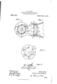
- Figure 1 is a Serial No. 498,444.
- Fig. 2 is a detail view of the attaching mechanism looking at it from the right of Fig. 1.
- Fig. 3 is a detail plan view of the locking or guard plate used in connection with the above described parts.
- Fig. 4 is a view taken on the irregular line 44 showing the relative positions of the guard plate and, the mouthpiece carrying member.
- the mouthpiece 10 made of glass, rubber or any suitable material, is preferably provided with an interior flange 12 such as is shown, described and claimed in my above mentioned prior application for use in this mouthpiece.
- a mouthpiece carrying member is provided consisting in the particular embodiment here illustrated of a flat plate member 14 provided throughout its surface with a plurality of holes 16 through which sound waves may freely pass and provided at its edge with short projecting spring dogs 18 adapted to engage the inner edge of the flange 12 as shown, and thus by such spring action hold the plate 14 within the mouthpiece 10 in the position shown in Fig.
- This plate 10 also has extending from it a plurality of flexible springs or arms 20 cut in the tapered lines 22- best seen in Fig. 4 converging in the outwardly turned fingers 24 adapted to enter the screw threads 26 out within the telephone transmitter box or case 28.
- a plate 30 is provided between the transmitter box 28 and the mouthpiece 10, having cut therein a plurality of pairs of locking dogs 32, 34 and 36 leaving the ends 38, 40 and -12 of the respective openings in the plate 30, thus formed at different radial distances from the center it of the plate 30, and the width of these dogs 32, 3t and 36, and consequently the openings in the plate 30 left by their partial removal is also of such a width that the arms 20 may, as best seen in Figs.
- the plate 80 is made of such a material and of such a stiffness and rigidity that when the locking fingers 32, 8st and 36 are formed in it, they will hold substantially their positions illustrated in Figs. 1 and 3 without influence by any spring pressure exerted by the arms 20.
- Fig. 1 a relatively large size transmitter box 28, and consequently in this particular case the arms 20 are inserted through the openings in the plate 30 adjacent to the locking fingers 32.
- the operator places the plate 30 with the arms 20 thus inserted adjacent to the open end of the transmitter box 28 and by rotating the plate 1a. and attached arms 20 causes the fingers 24k to travel around the screw threads 26 and thus through the plate 30 in the direction of the arrow 2 in Fig. 1.
- this operation is continued a given distance the inner faces of the arms 20 engage the locking members 32 as shown in F ig. 1, and are thereby sharply forced into more intimate contact than that heretofore existing with the threads 26 and after slightly passing the position of Fig.
- the operator takes the plate 30 and ascertains by examination whether the dogs 34 or 36 will most readily serve the purpose of locking the arms 20 in engagement with the threads of this new transmitter and having selected the proper dogs as for instance the locking members 36, he by hand springs the arms 20 into the openings left by these dogs 3st and the plate 30 and adjacent to the walls 40 thereof and then inserts the device in the same manner in this smaller transmitter.
- the tip of the arms 20 combines with the links of the locking arms 32; 34: or 36 as the case may be, to prevent a too energetic operator forcing the device to such a great distance within the transmitter that the fingers strip the screw threads within the transmitter.
- a member provided with means for detachably securing a transmitter mouthpiece thereto, arms upon said member extending beyond the end of a mouthpiece when it is attached to said member, and also adapted to enter and engage depressions in the interior of a transmitter box or case, a plate adapted to be inserted between the transmitter box or case and a mouthpiece upon said first mentioned member, there being openings in said plate through which said arms extending from the first mentioned member pass, and locking members carried by the plate and engaging the interior portions of said arms adapted to lock the arms in engagement with thetransmitter box or case, said arms being bent out from the material of the plate.
- a perforated fiat plate adapted to be inserted within and across the end of a mouthpiece, means for retaining said plate in the mouthpiece in said position, arms extending from said plate and of a suflicient length so that they extend outside of the mouthpiece when it is applied to said plate the opposite ends of said arms being adapted to enter and engage depressions in the interior of the transmitter box or case, a spring plate adapted to be inserted between the first mentioned plate and the transmitter 100:; or case, having openings therein through which said arms pass, and members carried by said plate engaging said arms to force them into engagement with the transmitter box or case.
- a member adapted to be inserted within and detachably secured Within a transmitter mouthpiece, fiaringly extending arms on said member having outwardly turned ends adapted to engage a recess within an adjacent transmitter case or box, a supplemental plate adapted to be inserted between the transmitter and the mouthpiece carried by said member, said plate being provided with a plurality of members at different radial distances from the center of the second mentioned plate, adapted to be selectively engaged by the arms upon the first mentioned member, for the purpose of locking said arms in engagement with transmitter boxes or cases of selected different internal diameters for the purposes described.
Landscapes
- Engineering & Computer Science (AREA)
- Signal Processing (AREA)
- Transmitters (AREA)
Description
M. W001). TELEPHONE TRANSMITTER .MOUTHPIBQE.
APPLIOATIONIIILED MAY 26, 1909.
- Patented Mar. 15,1920.
ANDREI/EU; GRAHAM C9. PHDTO-LITKDORAPNERS, WASHINGTON. D. O.
Cir
EPATNT @FFTQE.
MONTRAVILLE 1VL WOOD, 0F BERWYN, ILLINOIS, ASSIGNOR, BY MESNE ASSIGNMENTS,
TO W. H. FOLL, OF FREEPORT, ILLINOIS.
TELEPHONE-TRANSMITTER MOUTI-IPIEGE.
952,165. Specification lfitterslatent- Patented Mar. 15, 1918.
Application filed May 26, 1909.
To all whom it may concern:
Be it known that I, MONTRAVILLE M. V7001), a citizen of the United States, residing at Berwyn, in the county of Cook and State of Illinois, have invented a certain new and useful Improvement in Telephone- Transmitter Mouthpieces, of which the following is a specification.
My invention relates to telephone transmitter mouthpieces and particularly to means for securing the mouthpiece to the transmitter proper. Prior devices such for instance as that of my prior application No. 465,800 have used screw threads for this purpose, and this method is satisfactory where all of the transmitters to which the device is to be applied are of a given standard make, but it is a well know fact that there are many so called independent telephone companies in the field, all of which use transmitter boxes having their interiors of different diameters and threaded with different sizes of screw thread and when a commercial house sells transmitter mouthpieces such as that of my above mentioned application for use in any make of telephone transmitter box it becomes a serious problem to supply a mechanism by which a given standard mouthpiece may be readily attached to any and all forms and variety of transmitter box upon the market; and the object of this invention is to provide such a device which will readily adjust itself within reasonable limits to any size of transmitter box opening and pitch of screw threads therein whereby the given standard mouthpiece may be attached to any selected transmitter box.
A further object of the invention is to provide a mechanism of this type which automatically locks itself in the threads of the selected transmitter box and it is therefore not readily detachable therefrom.
The invention consists in mechanism capable of carrying out the foregoing objects, which can be very easily and cheaply made, whose operation may be readily understood by the ordinary mechanic and which is satisfactory in operation and not readily liable to get out of order.
The invention further consists in features of construction which will be hereafter more fully described and claimed as the specification proceeds.
Referring to the drawings, Figure 1 is a Serial No. 498,444.
central sectional side View of a transmitter case, a transmitter mouthpiece and the mechanism of this invention for securing the two together, the whole assembled in working position, said view being taken approximately on the line 1-1 of Fig. 2. Fig. 2 is a detail view of the attaching mechanism looking at it from the right of Fig. 1. Fig. 3 is a detail plan view of the locking or guard plate used in connection with the above described parts. Fig. 4 is a view taken on the irregular line 44 showing the relative positions of the guard plate and, the mouthpiece carrying member.
Again referring to the drawings, the mouthpiece 10 made of glass, rubber or any suitable material, is preferably provided with an interior flange 12 such as is shown, described and claimed in my above mentioned prior application for use in this mouthpiece. A mouthpiece carrying member is provided consisting in the particular embodiment here illustrated of a flat plate member 14 provided throughout its surface with a plurality of holes 16 through which sound waves may freely pass and provided at its edge with short projecting spring dogs 18 adapted to engage the inner edge of the flange 12 as shown, and thus by such spring action hold the plate 14 within the mouthpiece 10 in the position shown in Fig. 1 except when a sui'licientpulling force is exerted upon the mouthpiece 10 to overcome the spring action of the dogs 18 and thus pull the mouthpiece off from the plate 14 against the action of said spring dogs 18. This plate 10 also has extending from it a plurality of flexible springs or arms 20 cut in the tapered lines 22- best seen in Fig. 4 converging in the outwardly turned fingers 24 adapted to enter the screw threads 26 out within the telephone transmitter box or case 28. These fingers 24 being upon the ends of the spring arms 20 engage the screw threads 26 with some pressure and might be made to serve the purpose of holding the mouthpiece 10 in engagement with the transmitter, but in practice it is found that it only takes a very slight pull upon the transmitter mouthpiece 10 to cause these fingers 24 to click over the threads 26 and thus permit the ready removal of the mouthpiece 10, the plate 14 and the arms 20 from the transmitter instead of the mouthpiece slipping over the locking dogs 18 in the manner described. This is very objectionable for the reason that repeated removals will wear the threads 26 and ultimately render the "attachment of the device to the transmitter box 28 impossible.
In order to provide a locking mechanism which will hold these fingers 24 in positive engagement with the screw threads 26 and which will do this even though the device be inserted in transmitters of different sizes, a plate 30 is provided between the transmitter box 28 and the mouthpiece 10, having cut therein a plurality of pairs of locking dogs 32, 34 and 36 leaving the ends 38, 40 and -12 of the respective openings in the plate 30, thus formed at different radial distances from the center it of the plate 30, and the width of these dogs 32, 3t and 36, and consequently the openings in the plate 30 left by their partial removal is also of such a width that the arms 20 may, as best seen in Figs. 1 and 4:, descend through said openings a given predetermined distance before the angular sides 22 of the arms 20 engage the sides of such openings in the plate 30, but that at said point the arms 20 do engage the sides of these openings and further entry of the arms is impossible. The plate 80 is made of such a material and of such a stiffness and rigidity that when the locking fingers 32, 8st and 36 are formed in it, they will hold substantially their positions illustrated in Figs. 1 and 3 without influence by any spring pressure exerted by the arms 20.
The method of application of the device is I as follows: In Fig. 1 is shown a relatively large size transmitter box 28, and consequently in this particular case the arms 20 are inserted through the openings in the plate 30 adjacent to the locking fingers 32. The operator then places the plate 30 with the arms 20 thus inserted adjacent to the open end of the transmitter box 28 and by rotating the plate 1a. and attached arms 20 causes the fingers 24k to travel around the screw threads 26 and thus through the plate 30 in the direction of the arrow 2 in Fig. 1. \Vhen this operation is continued a given distance the inner faces of the arms 20 engage the locking members 32 as shown in F ig. 1, and are thereby sharply forced into more intimate contact than that heretofore existing with the threads 26 and after slightly passing the position of Fig. l are so rigidly held in position by the fingers 32 that removal of the members 24 from engagement with the screw threads 26 is impossible without absolutely stripping the threads 26. hen the plate 1-lhas thus been attached to the transmitter box 28 the operator takes the mouthpiece and slips it over plate 1% to the position shown in Fig. l. The mouthpiece may be removed by pulling it 01f against the action of the dogs 18 in the manner described. When it is desired to attach the device to another transmitter than that shown, having a smaller diameter of opening, the operator takes the plate 30 and ascertains by examination whether the dogs 34 or 36 will most readily serve the purpose of locking the arms 20 in engagement with the threads of this new transmitter and having selected the proper dogs as for instance the locking members 36, he by hand springs the arms 20 into the openings left by these dogs 3st and the plate 30 and adjacent to the walls 40 thereof and then inserts the device in the same manner in this smaller transmitter. It will be noticed that the tip of the arms 20 combines with the links of the locking arms 32; 34: or 36 as the case may be, to prevent a too energetic operator forcing the device to such a great distance within the transmitter that the fingers strip the screw threads within the transmitter.
The claims are:
1. In mechanism of the class described, the combination of a plate, means for detachably attaching a transmitter mouthpiece thereto, and arms projecting from said plate of such a length as to extend beyond the end of the mouthpiece attached to the plate, and means for detachably connecting such extending ends of the arms to recesses within a transmitter box or case to which the device is to be applied.
In mechanism of the class described, the combination of a member provided with means for detachably securing it to a transmitter mouthpiece, arms upon said member capable of normally extending beyond the position of a mouthpiece applied to said member, projecting portions on said arms adapted to enter recesses within a transmitter box or case, and a supplemental plate adapted to be interposed between the first mentioned device and the transmitter box or case, said plate being provided with mechanism engaging said arms and locking them in engagement with the interior of the transmitter box or case.
3. In a device of the class described, the combination of a member provided with means for detachably securing a transmitter mouthpiece thereto, arms upon said member extending beyond the end of a mouthpiece when it is attached to said member, and also adapted to enter and engage depressions in the interior of a transmitter box or case, a plate adapted to be inserted between the transmitter box or case and a mouthpiece upon said first mentioned member, there being openings in said plate through which said arms extending from the first mentioned member pass, and locking members carried by the plate and engaging the interior portions of said arms adapted to lock the arms in engagement with thetransmitter box or case, said arms being bent out from the material of the plate.
4. In mechanism of the class described, a perforated fiat plate adapted to be inserted within and across the end of a mouthpiece, means for retaining said plate in the mouthpiece in said position, arms extending from said plate and of a suflicient length so that they extend outside of the mouthpiece when it is applied to said plate the opposite ends of said arms being adapted to enter and engage depressions in the interior of the transmitter box or case, a spring plate adapted to be inserted between the first mentioned plate and the transmitter 100:; or case, having openings therein through which said arms pass, and members carried by said plate engaging said arms to force them into engagement with the transmitter box or case.
5. In mechanism of the class described, the combination of a member adapted to be inserted within and detachably secured Within a transmitter mouthpiece, fiaringly extending arms on said member having outwardly turned ends adapted to engage a recess within an adjacent transmitter case or box, a supplemental plate adapted to be inserted between the transmitter and the mouthpiece carried by said member, said plate being provided with a plurality of members at different radial distances from the center of the second mentioned plate, adapted to be selectively engaged by the arms upon the first mentioned member, for the purpose of locking said arms in engagement with transmitter boxes or cases of selected different internal diameters for the purposes described.
In witness whereof, I have hereunto subscribed my name in the presence of two witnesses.
MONTRAVILLE M. lVOOD.
WVitnesses DWIGHT B. CHEEVER, C. J. CHRISTOFIEL.
Priority Applications (1)
| Application Number | Priority Date | Filing Date | Title |
|---|---|---|---|
| US49844409A US952165A (en) | 1909-05-26 | 1909-05-26 | Telephone-transmitter mouthpiece. |
Applications Claiming Priority (1)
| Application Number | Priority Date | Filing Date | Title |
|---|---|---|---|
| US49844409A US952165A (en) | 1909-05-26 | 1909-05-26 | Telephone-transmitter mouthpiece. |
Publications (1)
| Publication Number | Publication Date |
|---|---|
| US952165A true US952165A (en) | 1910-03-15 |
Family
ID=3020575
Family Applications (1)
| Application Number | Title | Priority Date | Filing Date |
|---|---|---|---|
| US49844409A Expired - Lifetime US952165A (en) | 1909-05-26 | 1909-05-26 | Telephone-transmitter mouthpiece. |
Country Status (1)
| Country | Link |
|---|---|
| US (1) | US952165A (en) |
-
1909
- 1909-05-26 US US49844409A patent/US952165A/en not_active Expired - Lifetime
Similar Documents
| Publication | Publication Date | Title |
|---|---|---|
| CA120382A (en) | Hitching device | |
| CA117348A (en) | Poultry feeding device | |
| CA106705A (en) | Cord or rope holder | |
| GB190608957A (en) | A New or Improved Device or Seed Protector for Agricultural and like purposes. | |
| CA130872A (en) | Harness bit | |
| CA121102A (en) | Logging device | |
| CA117161A (en) | Apparatus for classifying and distributing telegrams | |
| CA99905A (en) | Chain securing device | |
| CA121578A (en) | Logging hook | |
| GB190616355A (en) | An Improved Box for Sticking Plaster and the like. | |
| CA108936A (en) | Feeding device for poultry | |
| CA105705A (en) | Horse bit | |
| GB190807213A (en) | A New or Improved Multiple Lubricating Device. | |
| CA100868A (en) | Sanding device | |
| CA106886A (en) | Harness hook | |
| CA116429A (en) | Harness | |
| CA123766A (en) | Harness | |
| CA100259A (en) | Percussive device | |
| CA103210A (en) | Hub attaching device | |
| CA100890A (en) | Horse training device | |
| CA98572A (en) | Hose binder | |
| CA100660A (en) | Printing device | |
| CA100737A (en) | Printing device | |
| CA122735A (en) | Computing device | |
| CA105837A (en) | Pacing device for horses |