US9520919B2 - Magnetic wireless ground data link for aircraft health monitoring - Google Patents
Magnetic wireless ground data link for aircraft health monitoring Download PDFInfo
- Publication number
- US9520919B2 US9520919B2 US14/168,412 US201414168412A US9520919B2 US 9520919 B2 US9520919 B2 US 9520919B2 US 201414168412 A US201414168412 A US 201414168412A US 9520919 B2 US9520919 B2 US 9520919B2
- Authority
- US
- United States
- Prior art keywords
- aircraft
- ground
- coil
- based coil
- magnetic field
- Prior art date
- Legal status (The legal status is an assumption and is not a legal conclusion. Google has not performed a legal analysis and makes no representation as to the accuracy of the status listed.)
- Active, expires
Links
Images


Classifications
-
- H—ELECTRICITY
- H04—ELECTRIC COMMUNICATION TECHNIQUE
- H04B—TRANSMISSION
- H04B5/00—Near-field transmission systems, e.g. inductive or capacitive transmission systems
- H04B5/70—Near-field transmission systems, e.g. inductive or capacitive transmission systems specially adapted for specific purposes
- H04B5/72—Near-field transmission systems, e.g. inductive or capacitive transmission systems specially adapted for specific purposes for local intradevice communication
-
- H—ELECTRICITY
- H04—ELECTRIC COMMUNICATION TECHNIQUE
- H04B—TRANSMISSION
- H04B5/00—Near-field transmission systems, e.g. inductive or capacitive transmission systems
- H04B5/20—Near-field transmission systems, e.g. inductive or capacitive transmission systems characterised by the transmission technique; characterised by the transmission medium
- H04B5/24—Inductive coupling
- H04B5/26—Inductive coupling using coils
-
- H04B5/0031—
-
- H—ELECTRICITY
- H01—ELECTRIC ELEMENTS
- H01Q—ANTENNAS, i.e. RADIO AERIALS
- H01Q7/00—Loop antennas with a substantially uniform current distribution around the loop and having a directional radiation pattern in a plane perpendicular to the plane of the loop
-
- H—ELECTRICITY
- H01—ELECTRIC ELEMENTS
- H01Q—ANTENNAS, i.e. RADIO AERIALS
- H01Q1/00—Details of, or arrangements associated with, antennas
- H01Q1/27—Adaptation for use in or on movable bodies
- H01Q1/28—Adaptation for use in or on aircraft, missiles, satellites, or balloons
-
- H04B5/0081—
-
- H—ELECTRICITY
- H04—ELECTRIC COMMUNICATION TECHNIQUE
- H04B—TRANSMISSION
- H04B5/00—Near-field transmission systems, e.g. inductive or capacitive transmission systems
- H04B5/20—Near-field transmission systems, e.g. inductive or capacitive transmission systems characterised by the transmission technique; characterised by the transmission medium
- H04B5/24—Inductive coupling
- H04B5/26—Inductive coupling using coils
- H04B5/266—One coil at each side, e.g. with primary and secondary coils
-
- H—ELECTRICITY
- H04—ELECTRIC COMMUNICATION TECHNIQUE
- H04B—TRANSMISSION
- H04B7/00—Radio transmission systems, i.e. using radiation field
- H04B7/14—Relay systems
- H04B7/15—Active relay systems
- H04B7/185—Space-based or airborne stations; Stations for satellite systems
- H04B7/18502—Airborne stations
- H04B7/18506—Communications with or from aircraft, i.e. aeronautical mobile service
-
- H—ELECTRICITY
- H04—ELECTRIC COMMUNICATION TECHNIQUE
- H04L—TRANSMISSION OF DIGITAL INFORMATION, e.g. TELEGRAPHIC COMMUNICATION
- H04L67/00—Network arrangements or protocols for supporting network services or applications
- H04L67/01—Protocols
- H04L67/12—Protocols specially adapted for proprietary or special-purpose networking environments, e.g. medical networks, sensor networks, networks in vehicles or remote metering networks
Definitions
- the present disclosure relates to aircraft communications and, more specifically, to systems and methods of wireless communications between an aircraft on the ground and a ground-based location.
- Aircraft are routinely equipped with sensors to establish estimates of wear and tear, load conditions, etc., so that maintenance may be carried out in a proactive manner.
- This data is downloaded to ground-based computers for further analysis and processing after the aircraft has landed.
- Current technologies for downloading aircraft data may include wireless communication in frequency bands around 2.4 Gigahertz (GHz) and commercial communication frequencies such as Groupe Special Mobile (GSM) or Code Division Multiple Access (CDMA) standards.
- GSM Groupe Special Mobile
- CDMA Code Division Multiple Access
- a method of communicating a signal includes: moving an aircraft so that a aircraft-based coil is within a selected volume defined by a ground-based coil; modulating a current in one of the aircraft-based coil and the ground-based coil to generate a magnetic field in the volume; and communicating the signal by measuring a current generated in the other of the aircraft-based coil and the ground-based coil in response to the generated magnetic field.
- a communication system includes: a ground-based coil; a ground-based transceiver configured to generate and measure a magnetic field at the ground-based coil to communicate a signal; an aircraft movable with respect to the ground-based coil; an aircraft-based coil conveyed on an aircraft; and a transceiver conveyed on the aircraft configured to generate and measure a magnetic field at the aircraft-based coil to communicate the signal.
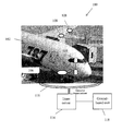
- FIG. 1 shows an exemplary communication system between an aircraft at a ground location and a ground-based unit
- FIG. 2 shows another embodiment of the communication system for use with a commuter-type aircraft
- FIG. 3 shows yet another embodiment of the communication system in which the aircraft is a helicopter
- FIG. 4 illustrates a signal communication protocol that may be used with the illustrative communication systems shown in FIGS. 1-3 ;
- FIG. 5 shows a flowchart illustrating a communication method of the present disclosure.
- FIG. 1 shows an example of a communication system 100 allowing communication between an aircraft 100 at a ground location and a ground-based unit 118 .
- the aircraft 102 that may be any form of aircraft, such as a passenger aircraft, commuter aircraft, helicopter, etc.
- a transceiver 104 that is coupled to an aircraft-based coil 106 , with both transceiver 104 and aircraft-based coil 106 being located on aircraft 102 .
- the aircraft-based coil 106 may be a magnetic loop antenna, in one embodiment.
- the transceiver 104 may be coupled to one or more sensors 108 located in the aircraft.
- the sensors 108 may be located at various locations in the aircraft and may be configured to obtain data relating to health of the aircraft, force on the aircraft in flight, or other data that may be of interest to ground crew, airplane designers, etc.
- the obtained data may be sent from the sensors 108 to the transceiver 104 or to a memory storage device 103 on the aircraft 102 .
- the transceiver 104 may produce or modulate a current in the aircraft-based coil 106 to generate a magnetic field.
- the modulation of the coil may be selected to encode a signal in the generated magnetic field.
- the encoded signal may be related to the data obtained at the sensors 108 .
- the transceiver 104 may measure or monitor a current generated in the coil 106 in response to a modulating magnetic field.
- the system 100 further includes a ground-based transceiver 114 coupled to a ground-based coil 116 , which may be a magnetic loop antenna in one embodiment. Similar to the transceiver of the aircraft 102 , in a transmitting mode of operation, the transceiver 114 may produce or modulate a current in the ground-based coil 116 to generate a magnetic field. In a receiving mode of operation, the ground-based transceiver 114 may measure or monitor a current generated in the aircraft-based coil 106 in response to a modulating magnetic field.
- data may be transmitted from the aircraft 102 to a suitable ground-based unit 118 , such as a ground-based control unit, processor or database, for example.
- a suitable ground-based unit 118 such as a ground-based control unit, processor or database, for example.
- data may be transmitted from the ground-based unit 118 to the aircraft 102 .
- the ground-based coil 116 may be several meters in diameter or having a cross-sectional area large enough to substantially encompass a cockpit area of a passenger aircraft, or an area spanned by small aircraft such as a commuter type fixed wing jet or a helicopter.
- the ground-based coil 116 may lie flat along the ground with its normal facing perpendicular to the ground or airplane surface.
- the airplane may taxi along the ground to the location of the ground-based coil 116 so that the aircraft-based coil 106 is located within or above the ground-based coil 116 in order to establish a communication link between the aircraft 102 and the ground-based unit 118 .
- the aircraft-based coil 106 may be moved to within a volume that is defined by or is affected by a magnetic field that is generated at the ground-based coil 116 .
- the airplane may break the communication link by taxiing away from the ground-based coil 116 .
- a magnetic field generated at the ground-based coil 116 may be detected at the aircraft-based coil 106 of the aircraft 102 and a magnetic field generated at the aircraft-based coil 106 may be detected at the ground-based coil 106 .
- An annunciator in the cockpit may indicate to the pilot that the aircraft 102 is within acceptable range of the ground-based coil 116 .
- the ground crew directing the aircraft 102 may use a visual alignment marking or a positive electrical indicator (e.g., sound or light) to confirm that the aircraft 102 is positioned appropriately for wireless communication.
- the ground-based coil 116 may be located at a hanger location, an aircraft boarding location, an aircraft de-icing station; a resting location of the aircraft, or other suitable location on the ground.
- the ground-based coil 116 may be buried underneath the ground surface or laid on top of a ground surface, positioned in such a way as to be in close proximity to the aircraft 102 . Other such positions may include mounting the ground-based coil 116 on a movable gateway, a ground service vehicle or a refueling vehicle.
- FIG. 1 shows an illustrative example in which the aircraft 102 is a passenger aircraft such as the Boeing 747, 757, 767, 777, 787, the Airbus A380, etc.
- the aircraft-based coil 106 may be located below a cockpit location of the aircraft 102 .
- the ground-based coil 116 is located at the boarding area where the cockpit may be located during a boarding operation. Therefore, the information may be communicated while passenger are de-boarding and boarding the aircraft 102 .
- FIG. 2 shows another embodiment of the communication system for use with a commuter-type aircraft 202 .
- the ground-based coil 216 has a diameter that is approximately the same as a length or width of the aircraft 202 .
- FIG. 3 shows yet another embodiment of the communication system in which the aircraft is a helicopter. As in FIG. 2 , the diameter of the ground-based coil is approximately the same as the length of the helicopter.
- FIG. 4 illustrates a signal communication protocol that may be used with the illustrative communication systems shown in FIGS. 1-3 .
- the aircraft For many aircraft, such as passenger aircraft, for example, the aircraft is on the ground for a designated amount of time before it is takes off for its next destination. In addition, the aircraft may be stationary for only a short amount of its time on the ground, such as during a boarding and de-boarding operation, for example.
- the communication system 100 transfers all or most of its data from the aircraft to the ground-based unit during this time.
- the present disclosure therefore combines pulse width modulation with amplitude modulation to achieve desired performance of multiple bits/baud.
- the achievable efficiency of this system referred to herein as called Pulse Amplitude Width System or PAWS, may be increased via improved circuit techniques, etc.
- FIG. 4 shows a matrix of illustrative pulse characteristics used in the PAWS protocol to achieve a selected communication efficiency.
- the selected communication efficiency is about two bits/baud.
- Signal pulse duration is shown along the horizontal axis and signal magnitude is shown along the vertical axis.
- a signal may include a pulse characterized by both its magnitude and duration.
- the pulse duration may be one of two time durations (e.g., 1 millisecond and 2 milliseconds) while the pulse amplitude may be one of two values (e.g., 0.5 volts and 1.0 volts).
- Various combinations of these various pulse characteristics produces four different states, which may therefore be used to represent binary bit pairs. For example, bit pair ‘00’ may be transmitted using a pulse having a magnitude of 0.5 V and having a duration of 1 millisecond.
- the table shown in FIG. 4 describes the pulse characteristics for each bit pair.
- FIG. 5 shows a flowchart 500 illustrating a communication method of the present disclosure.
- an aircraft taxis to a location of a ground-based coil so that an aircraft-based coil is within a volume affected by a magnetic field generated at the ground-based coil.
- a current may be modulated at the aircraft-based coil to generate a magnetic field. The modulation of the current is according to a communication protocol for transferring data from the aircraft to a ground-based unit, such as the protocol illustrated in FIG. 4 .
- the magnetic field generated at the aircraft-based coil produces a current in the ground-based coil, and the current in the ground-based coil is measured to read the data from the aircraft.
- the read data is sent to a ground-based unit for further processing and review. It is to be noted that communication from the ground-based unit to the aircraft may also be performed by generating the magnetic field in the ground-based coil and reading currents in the aircraft-based coil that are in response to the generated magnetic field.
- the present disclosure therefore enables wireless transfer of data stored in an aircraft to ground-based units by using magnetic field radio frequency (RF) signals.
- RF magnetic field radio frequency
- the magnetic field RF communication decays at about 60 decibels/decade (dB/decade) vs. 20 dB/decade for electric field RF communications.
- the magnetic field RF communication is more resistant to jamming techniques than electric field RF communication.
- the magnetic field RF communication is more secure and allows less eavesdropping.
- signals may be generally below a threshold of detection at distances beyond 3 meters away from the ground-based coil, using present technologies.
- the magnetic field RF signals do not share the same frequency bands as present electric field RF signals.
- commercial communication may be performed substantially simultaneously with the magnetic field communication, with reduced interference with the bandwidth of tablet computers, laptops, smartphones, etc.
- due to the decay rate of magnetic field RF signals data communication to and from a single aircraft may not interfere with data communication from neighboring aircraft. Therefore, a communication system may be established for a plurality of densely-parked aircraft using a plurality of densely packed ground-based coils, where each coil is at an assigned parking area for commuter aircraft or at boarding areas of passenger aircraft at large hub airports.
Landscapes
- Engineering & Computer Science (AREA)
- Computer Networks & Wireless Communication (AREA)
- Signal Processing (AREA)
- Aviation & Aerospace Engineering (AREA)
- Physics & Mathematics (AREA)
- Astronomy & Astrophysics (AREA)
- General Physics & Mathematics (AREA)
- Medical Informatics (AREA)
- General Health & Medical Sciences (AREA)
- Computing Systems (AREA)
- Health & Medical Sciences (AREA)
- Remote Sensing (AREA)
- Near-Field Transmission Systems (AREA)
- Arrangements For Transmission Of Measured Signals (AREA)
Abstract
Description
Claims (14)
Priority Applications (6)
| Application Number | Priority Date | Filing Date | Title |
|---|---|---|---|
| US14/168,412 US9520919B2 (en) | 2014-01-30 | 2014-01-30 | Magnetic wireless ground data link for aircraft health monitoring |
| CA2876750A CA2876750A1 (en) | 2014-01-30 | 2014-12-22 | Magnetic wireless ground data link for aircraft health monitoring |
| JP2014258174A JP2015142378A (en) | 2014-01-30 | 2014-12-22 | Signal communication method and communication system |
| CN201410828870.8A CN104821077B (en) | 2014-01-30 | 2014-12-26 | magnetic wireless ground data link for aircraft health monitoring |
| EP14200419.1A EP2903179B1 (en) | 2014-01-30 | 2014-12-29 | Magnetic wireless ground data link for aircraft state monitoring |
| BR102014032848-3A BR102014032848A2 (en) | 2014-01-30 | 2014-12-29 | method of communicating a signal, and, communication system. |
Applications Claiming Priority (1)
| Application Number | Priority Date | Filing Date | Title |
|---|---|---|---|
| US14/168,412 US9520919B2 (en) | 2014-01-30 | 2014-01-30 | Magnetic wireless ground data link for aircraft health monitoring |
Publications (2)
| Publication Number | Publication Date |
|---|---|
| US20150215004A1 US20150215004A1 (en) | 2015-07-30 |
| US9520919B2 true US9520919B2 (en) | 2016-12-13 |
Family
ID=52444065
Family Applications (1)
| Application Number | Title | Priority Date | Filing Date |
|---|---|---|---|
| US14/168,412 Active 2034-05-19 US9520919B2 (en) | 2014-01-30 | 2014-01-30 | Magnetic wireless ground data link for aircraft health monitoring |
Country Status (6)
| Country | Link |
|---|---|
| US (1) | US9520919B2 (en) |
| EP (1) | EP2903179B1 (en) |
| JP (1) | JP2015142378A (en) |
| CN (1) | CN104821077B (en) |
| BR (1) | BR102014032848A2 (en) |
| CA (1) | CA2876750A1 (en) |
Citations (8)
| Publication number | Priority date | Publication date | Assignee | Title |
|---|---|---|---|---|
| US6047165A (en) | 1995-11-14 | 2000-04-04 | Harris Corporation | Wireless, frequency-agile spread spectrum ground link-based aircraft data communication system |
| US6163681A (en) | 1999-06-25 | 2000-12-19 | Harris Corporation | Wireless spread spectrum ground link-based aircraft data communication system with variable data rate |
| US6181990B1 (en) | 1998-07-30 | 2001-01-30 | Teledyne Technologies, Inc. | Aircraft flight data acquisition and transmission system |
| US20030130769A1 (en) | 2002-11-14 | 2003-07-10 | Farley Rod J. | Aircraft data transmission system for wireless communication of data between the aircraft and ground-based systems |
| US6816728B2 (en) | 2002-04-24 | 2004-11-09 | Teledyne Technologies Incorporated | Aircraft data communication system and method |
| US20090070841A1 (en) * | 2007-09-12 | 2009-03-12 | Proximetry, Inc. | Systems and methods for delivery of wireless data and multimedia content to aircraft |
| WO2011044695A1 (en) | 2009-10-13 | 2011-04-21 | Cynetic Designs Ltd. | An inductively coupled power and data transmission system |
| US20130005251A1 (en) | 2007-12-21 | 2013-01-03 | Cynetic Designs Ltd. | Vehicle seat inductive charger and data transmitter |
Family Cites Families (14)
| Publication number | Priority date | Publication date | Assignee | Title |
|---|---|---|---|---|
| JPS4833198Y1 (en) * | 1969-04-30 | 1973-10-08 | ||
| JPS61203737A (en) * | 1985-03-06 | 1986-09-09 | Omron Tateisi Electronics Co | Communication system between vehicles on road |
| US5084864A (en) * | 1990-05-14 | 1992-01-28 | The Boeing Company | Broadband, inductively coupled, duplex, rf transmission system |
| US5295212A (en) * | 1992-10-29 | 1994-03-15 | Eldec Corporation | System for transmitting signals between optical transceivers |
| JP2001206297A (en) * | 2000-01-21 | 2001-07-31 | Japan Aircraft Mfg Co Ltd | Aircraft operation and maintenance information management system |
| JP2003030611A (en) * | 2001-07-18 | 2003-01-31 | Nippon Telegr & Teleph Corp <Ntt> | Wireless communication module and wireless communication method |
| US20040229607A1 (en) * | 2003-05-12 | 2004-11-18 | La Chapelle Michael De | Wireless communication inside shielded envelope |
| SE0302681D0 (en) * | 2003-10-09 | 2003-10-09 | Bang & Olufsen Icepower As | Method of pulse area modulation |
| US7620374B2 (en) * | 2004-09-16 | 2009-11-17 | Harris Corporation | System and method of transmitting data from an aircraft |
| JP4772744B2 (en) * | 2007-05-17 | 2011-09-14 | 昭和飛行機工業株式会社 | Signal transmission coil communication device for non-contact power feeding device |
| DE102008048500A1 (en) * | 2008-09-23 | 2010-04-15 | Airbus Deutschland Gmbh | Lockable device with data and energy transmission through electromagnetic induction |
| US20110022113A1 (en) * | 2008-12-02 | 2011-01-27 | Mark Zdeblick | Analyzer Compatible Communication Protocol |
| DE102010055696A1 (en) * | 2010-12-22 | 2012-06-28 | Airbus Operations Gmbh | A system for contactless energy transfer, use of a system for contactless energy transfer and vehicle with a system for contactless energy transfer between a first vehicle part and a second vehicle part |
| JP2013244785A (en) * | 2012-05-24 | 2013-12-09 | Sinfonia Technology Co Ltd | Power supply system for aircraft and power supply vehicle for aircraft |
-
2014
- 2014-01-30 US US14/168,412 patent/US9520919B2/en active Active
- 2014-12-22 JP JP2014258174A patent/JP2015142378A/en active Pending
- 2014-12-22 CA CA2876750A patent/CA2876750A1/en not_active Abandoned
- 2014-12-26 CN CN201410828870.8A patent/CN104821077B/en active Active
- 2014-12-29 BR BR102014032848-3A patent/BR102014032848A2/en not_active Application Discontinuation
- 2014-12-29 EP EP14200419.1A patent/EP2903179B1/en active Active
Patent Citations (9)
| Publication number | Priority date | Publication date | Assignee | Title |
|---|---|---|---|---|
| US6047165A (en) | 1995-11-14 | 2000-04-04 | Harris Corporation | Wireless, frequency-agile spread spectrum ground link-based aircraft data communication system |
| US6181990B1 (en) | 1998-07-30 | 2001-01-30 | Teledyne Technologies, Inc. | Aircraft flight data acquisition and transmission system |
| US6163681A (en) | 1999-06-25 | 2000-12-19 | Harris Corporation | Wireless spread spectrum ground link-based aircraft data communication system with variable data rate |
| US6816728B2 (en) | 2002-04-24 | 2004-11-09 | Teledyne Technologies Incorporated | Aircraft data communication system and method |
| US20030130769A1 (en) | 2002-11-14 | 2003-07-10 | Farley Rod J. | Aircraft data transmission system for wireless communication of data between the aircraft and ground-based systems |
| US20090070841A1 (en) * | 2007-09-12 | 2009-03-12 | Proximetry, Inc. | Systems and methods for delivery of wireless data and multimedia content to aircraft |
| US20130005251A1 (en) | 2007-12-21 | 2013-01-03 | Cynetic Designs Ltd. | Vehicle seat inductive charger and data transmitter |
| US9126514B2 (en) * | 2007-12-21 | 2015-09-08 | Cynetic Designs Ltd | Vehicle seat inductive charger and data transmitter |
| WO2011044695A1 (en) | 2009-10-13 | 2011-04-21 | Cynetic Designs Ltd. | An inductively coupled power and data transmission system |
Non-Patent Citations (1)
| Title |
|---|
| The extended European search report; Dated: Jul. 17, 2015; Application No. EP14200419; pp. 1-6. |
Also Published As
| Publication number | Publication date |
|---|---|
| EP2903179A3 (en) | 2015-08-19 |
| JP2015142378A (en) | 2015-08-03 |
| EP2903179B1 (en) | 2017-02-15 |
| US20150215004A1 (en) | 2015-07-30 |
| BR102014032848A2 (en) | 2020-07-07 |
| CN104821077B (en) | 2018-04-27 |
| EP2903179A2 (en) | 2015-08-05 |
| CN104821077A (en) | 2015-08-05 |
| CA2876750A1 (en) | 2015-07-30 |
Similar Documents
| Publication | Publication Date | Title |
|---|---|---|
| EP3046273B1 (en) | System and method for connecting aircraft to networks on ground | |
| US8634827B2 (en) | Techniques for reporting on or tracking ground vehicles | |
| US10110297B2 (en) | Aircraft comprising a plurality of antenna units | |
| EP4203333B1 (en) | Method and apparatus for physical security over a powerline connection | |
| US20160365917A1 (en) | Aircraft communications during different phases of flight | |
| US20200396602A1 (en) | Aircraft interface device | |
| US11231276B2 (en) | Aircraft-based radio frequency surveying | |
| US20180026707A1 (en) | System and method for re-broadcasting ads-b data | |
| US9520919B2 (en) | Magnetic wireless ground data link for aircraft health monitoring | |
| KR20240054268A (en) | Airport signaling system with ultra-wideband communication capabilities | |
| Chung et al. | A 1090 extended squitter automatic dependent surveillance-Broadcast (ADS-B) reception model for air-traffic-management simulations | |
| KR102802660B1 (en) | Method for contacting the channel of unmanned aerial vehicle(uav) control and non-payload communications(cnpc) system | |
| RS64083B1 (en) | Communication device for rail vehicle, rail vehicle equipped with said device | |
| US9030348B2 (en) | Systems and methods for providing diversity-distance-measuring equipment | |
| Wu et al. | Research on the influence of drone countermeasure equipment on the surveillance system used in civil aviation | |
| Steingass et al. | Airborne measurements of DME interferers at the European hotspot | |
| US10059355B2 (en) | Communication device for rail vehicle, rail vehicle equipped with said device | |
| Morioka et al. | 5GHz ground-to-air communication link by AeroMACS in high-speed movement scenarios | |
| Beck et al. | Cellular 4G LTE aeronautical mobile telemetry flight test results | |
| Kanada et al. | Signal evaluation on airport surface in 5.1 Ghz band | |
| Mendoza et al. | On the application of three dimensional HAP MIMO model in UAV environment | |
| US11467249B2 (en) | Interval management using data overlay | |
| Hall et al. | Nextgen ATS Communications, Navigation, And Surveillance Test Bed | |
| Apaza | Wireless communications for airport surface: an evaluation of requirements | |
| Kopyt et al. | Remotely powered wireless dual-band sensing system for aircraft EMC environment |
Legal Events
| Date | Code | Title | Description |
|---|---|---|---|
| AS | Assignment |
Owner name: SIMMONDS PRECISION PRODUCTS, INC., VERMONT Free format text: ASSIGNMENT OF ASSIGNORS INTEREST;ASSIGNORS:BAJEKAL, SANJAY;LYNCH, MICHAEL ANTHONY;SIGNING DATES FROM 20140114 TO 20140128;REEL/FRAME:032094/0626 |
|
| STCF | Information on status: patent grant |
Free format text: PATENTED CASE |
|
| MAFP | Maintenance fee payment |
Free format text: PAYMENT OF MAINTENANCE FEE, 4TH YEAR, LARGE ENTITY (ORIGINAL EVENT CODE: M1551); ENTITY STATUS OF PATENT OWNER: LARGE ENTITY Year of fee payment: 4 |
|
| MAFP | Maintenance fee payment |
Free format text: PAYMENT OF MAINTENANCE FEE, 8TH YEAR, LARGE ENTITY (ORIGINAL EVENT CODE: M1552); ENTITY STATUS OF PATENT OWNER: LARGE ENTITY Year of fee payment: 8 |
|
| AS | Assignment |
Owner name: GOLDMAN SACHS BANK USA, AS AGENT, NEW YORK Free format text: SECURITY INTEREST;ASSIGNOR:SIMMONDS PRECISION PRODUCTS, INC.;REEL/FRAME:073465/0631 Effective date: 20251104 |
|
| AS | Assignment |
Owner name: THE BANK OF NEW YORK MELLON TRUST COMPANY, N.A., ILLINOIS Free format text: SECURITY INTEREST;ASSIGNOR:SIMMONDS PRECISION PRODUCTS, INC.;REEL/FRAME:073545/0454 Effective date: 20251104 Owner name: THE BANK OF NEW YORK MELLON TRUST COMPANY, N.A., ILLINOIS Free format text: SECURITY INTEREST;ASSIGNOR:SIMMONDS PRECISION PRODUCTS, INC.;REEL/FRAME:073590/0028 Effective date: 20251104 Owner name: THE BANK OF NEW YORK MELLON TRUST COMPANY, N.A., ILLINOIS Free format text: SECURITY INTEREST;ASSIGNOR:SIMMONDS PRECISION PRODUCTS, INC.;REEL/FRAME:073560/0086 Effective date: 20251104 Owner name: THE BANK OF NEW YORK MELLON TRUST COMPANY, N.A., ILLINOIS Free format text: SECURITY INTEREST;ASSIGNOR:SIMMONDS PRECISION PRODUCTS, INC.;REEL/FRAME:073560/0144 Effective date: 20251104 Owner name: THE BANK OF NEW YORK MELLON TRUST COMPANY, N.A., ILLINOIS Free format text: SECURITY INTEREST;ASSIGNOR:SIMMONDS PRECISION PRODUCTS, INC.;REEL/FRAME:073545/0100 Effective date: 20251104 Owner name: THE BANK OF NEW YORK MELLON TRUST COMPANY, N.A., ILLINOIS Free format text: SECURITY INTEREST;ASSIGNOR:SIMMONDS PRECISION PRODUCTS, INC.;REEL/FRAME:073560/0181 Effective date: 20251104 Owner name: THE BANK OF NEW YORK MELLON TRUST COMPANY, N.A., ILLINOIS Free format text: SECURITY INTEREST;ASSIGNOR:SIMMONDS PRECISION PRODUCTS, INC.;REEL/FRAME:073560/0239 Effective date: 20251104 |