US9516223B2 - Motion-based image stitching - Google Patents
Motion-based image stitching Download PDFInfo
- Publication number
- US9516223B2 US9516223B2 US13/490,326 US201213490326A US9516223B2 US 9516223 B2 US9516223 B2 US 9516223B2 US 201213490326 A US201213490326 A US 201213490326A US 9516223 B2 US9516223 B2 US 9516223B2
- Authority
- US
- United States
- Prior art keywords
- image
- processor
- motion data
- cause
- translation
- Prior art date
- Legal status (The legal status is an assumption and is not a legal conclusion. Google has not performed a legal analysis and makes no representation as to the accuracy of the status listed.)
- Expired - Fee Related, expires
Links
Images


Classifications
-
- H04N5/23238—
-
- H—ELECTRICITY
- H04—ELECTRIC COMMUNICATION TECHNIQUE
- H04N—PICTORIAL COMMUNICATION, e.g. TELEVISION
- H04N23/00—Cameras or camera modules comprising electronic image sensors; Control thereof
- H04N23/60—Control of cameras or camera modules
- H04N23/698—Control of cameras or camera modules for achieving an enlarged field of view, e.g. panoramic image capture
-
- G—PHYSICS
- G06—COMPUTING OR CALCULATING; COUNTING
- G06T—IMAGE DATA PROCESSING OR GENERATION, IN GENERAL
- G06T3/00—Geometric image transformations in the plane of the image
- G06T3/40—Scaling of whole images or parts thereof, e.g. expanding or contracting
- G06T3/4038—Image mosaicing, e.g. composing plane images from plane sub-images
-
- H—ELECTRICITY
- H04—ELECTRIC COMMUNICATION TECHNIQUE
- H04N—PICTORIAL COMMUNICATION, e.g. TELEVISION
- H04N23/00—Cameras or camera modules comprising electronic image sensors; Control thereof
- H04N23/60—Control of cameras or camera modules
- H04N23/68—Control of cameras or camera modules for stable pick-up of the scene, e.g. compensating for camera body vibrations
- H04N23/681—Motion detection
- H04N23/6812—Motion detection based on additional sensors, e.g. acceleration sensors
-
- H04N5/23258—
Definitions
- This disclosure relates generally to the field of image processing. More particularly, but not by way of limitation, this disclosure relates to techniques for improving real-time panoramic photography processing using motion data (e.g., gyroscopic sensor input).
- motion data e.g., gyroscopic sensor input
- Panoramic photography may be defined generally as a photographic technique for capturing images with elongated fields of view.
- panoramic images generally have an aspect ratio of at least 2:1, meaning that the image is at least twice as wide as it is high (or, conversely, twice as high as it is wide, in the case of vertical panoramic images).
- panoramic images may even cover fields of view of up to 360 degrees, i.e., a “full rotation” panoramic image.
- panoramic photography systems may utilize gyroscopic information to assist in image analysis and registration.
- gyroscopic information As the number of images within a given time period that are aligned to generate a panoramic image increases, however, the computational costs of performing image analysis and registration can become prohibitive. This may be particularly true for image capture devices embedded in handheld electronic devices such as mobile phones, personal data assistants (PDAs), portable music players, digital cameras, as well as laptop and tablet computer systems.
- the invention provides a method to align or stitch together digital images without analyzing the image or performing standard image registration (both generally computationally expensive operations).
- the method includes obtaining a first image from an image capture device (e.g., a digital camera).
- motion information for the first image may be obtained (e.g., from a gyroscopic and/or accelerometer sensors).
- a second image having a focal length may then be obtained.
- motion data for the second image may be obtained at substantially the same time that the second image is obtained.
- a rotation metric between the two images e.g., due to motion of the image capture device
- sensor output data may be determined.
- a translation measure for the second image, relative to the first image, may be determined based on the rotation metric and the focal length.
- the second image may then be aligned with the first image using the translation measure.
- the translation measure may include a first translation measure for a first axis and a second translation measure for a second axis. It is significant that the two images may be aligned without performing standard image processing or analysis.
- the disclosed methods may be embodied in program code and stored on a non-transitory storage medium.
- the stored program code may be executed by a programmable control device that is part of, or controls, an image capture device.
- FIG. 1 shows, in flowchart form, an image stitching operation in accordance with one embodiment.
- FIGS. 2A and 2B show, in block diagram form, two different embodiments for correlating image data with motion data.
- FIG. 3 shows, in flowchart form, motion data being processed and attached to image data in accordance with one embodiment.
- FIGS. 4A and 4B show how rotational information between two images may be determined in accordance with one embodiment.
- FIG. 5 shows, in flowchart form, a perspective transform matrix generation operation in accordance with one embodiment.
- FIG. 6 shows, in flowchart form, an image stitching operation in accordance with another embodiment.
- FIG. 7 shows, in flowchart form, an image stitching operation in accordance with another embodiment.
- FIG. 8 shows the alignment of two consecutive images based on the calculation of a motion vector in accordance with the embodiment of FIG. 7 .
- FIG. 9 shows, in block diagram form, an image capture device in accordance with one embodiment.
- FIG. 10 shows an illustrative electronic device incorporating image stitching capability in accordance with this disclosure.
- FIGS. 11A and 11B show, in a functional block diagram, two illustrative devices capable of performing image stitching in accordance with this disclosure.
- FIG. 12 shows, in block diagram form, an electronic device in accordance with one embodiment.
- This disclosure pertains to systems, methods, and computer readable media for stitching or aligning multiple images (or portions of images) to generate a panoramic image.
- techniques are disclosed for using motion data (captured at substantially the same time as image data) to align images rather than performing standard image analysis and/or registration operations. More particularly, motion data derived from sensor output may be used to identify the rotational change between two images. The identified rotational change may be used to directly align/stitch the images.
- image stitching operation 100 begins by capturing raw image sequence 105 (block 110 ) and corresponding motion data 115 (block 120 ). Motion data 115 may then be attached to individual images within raw image sequence 105 (block 125 ) to produce image sequence 130 . It can be advantageous to capture motion data for each image in raw image sequence 105 so that each captured image has a corresponding motion datum. It can also be advantageous, and is common, for each image in an image sequence to have a timestamp indicating when the particular image was captured (e.g., during acts in accordance with block 110 ). The rotational change between successive images in image sequence 130 may be identified (block 135 ) and used to generate a perspective transform matrix (block 140 ). Applying the perspective transform to a “current” image (block 145 ) allows it to be aligned with a previously captured image (block 150 ) to produce aligned image sequence 155 , a panoramic image.
- image capture operation 110 may be preformed by sensor array 200 and motion data capture operation 120 may be performed by gyroscopic sensor (gyro) 205 .
- Sensor array 200 may capture black and white or color images and use, for example, complementary metal-oxide semiconductor (CMOS) or charged-coupled device (CCD) technology.
- CMOS complementary metal-oxide semiconductor
- CCD charged-coupled device
- Gyro sensor 205 may be used to generate rotation rate data in three dimensions (e.g., (x, y, z) or (pitch, roll, yaw) or in a quaternion system).
- Gyro sensor 205 may use any desired technology such as micro-electromechanical systems (MEMS) technology.
- MEMS micro-electromechanical systems
- image sensor 200 may signal gyro sensor 205 each time an image is captured through, for example, the V sync signal.
- Gyro sensor 205 may tag each “next captured” motion datum each time a V sync signal is received. This permits each image in raw image sequence 105 to be correlated or associated with the proper motion data.
- common clock 210 may drive both image sensor array 200 and gyro 205 . This arrangement permits the synchronous capture of image and motion data.
- motion data 115 may be attached to image data (i.e., each image in raw image sequence 105 ) through process 125 .
- rate information the rate at which the image capture device is being moved in each of, for example, 3 axis.
- Rate information may be integrated (block 300 ) to produce instantaneous rotation position information 305 (also in each of 3 axis).
- image timestamp information each image in raw image sequence 105 may be associated with the appropriate rotation position information 305 (block 310 ).
- operation 125 may also use accelerometer input 315 to assist in calibrating gyro sensor 205 's output.
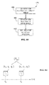
- FIG. 3 is a high-level representation of a single image frame 320 from image sequence 130 .
- image 320 includes data 325 representing the image itself and timestamp 330 provided during acts in accordance with block 110 .
- image 320 may also include position information 305 .
- identifying the relative rotation between successive images 135 begins by identifying the rotation position of the current image (block 400 ) and the rotation position of a prior image (block 405 ) upon which rotation for the current image is to be based (e.g., the immediately prior frame). As described above, this information may be attached to each image in accordance with block 125 (see also, FIG. 3 ). These two positions may be used to determine the rotation of the current image relative to the prior image. This operation may then be repeated for the next image in image sequence 130 and so on. Referring to FIG. 4B , two images from image sequence 130 are shown.
- Prior image I p was captured at time t p and has rotation position information x p , y p , and z p .
- Current image I c was taken at time t c and has rotation position information x c , y c , and z c .
- the difference between the rotation position of image I p and image I c represents the amount of rotation experienced by the image capture unit between time t p and t c and can be represented by a 3 ⁇ 3 rotation matrix denoted [R pc ] and associated with image I c .
- rotation matrix [R pc ] may be generated in accordance with any of a number of techniques but is not, in general, the algebraic difference between the rotation position of image I p and image I c .
- a perspective transform for each image in image sequence 130 in accordance with block 140 obtains various parameter values from the image capture device (block 500 ).
- Illustrative parameters include the focal length used to capture an image and the image capture device's principal point. It will be recognized that on image capture devices that provide the capability to move their lens and/or image sensor assemblies, the focal length may change from image to image.
- the device's intrinsic matrix may be found or generated (block 505 ). It will be understood that an image's intrinsic matrix links the pixel coordinates of an object point with the corresponding coordinates in the image capture device's reference frame.
- An image's perspective transform matrix may then be generated for a particular image using the image capture device's intrinsic matrix associated with that image (i.e., the intrinsic matrix generated using device parameter values that were in place when the image was captured) and the image's associated rotation matrix (block 510 ).
- a perspective transform matrix for a given image may be derived as follows. First, it will be recognized by those of skill in the art that the 2D projection of real-space (which is 3D) onto a sensor array (which is 2D) may be given as—
- EQ. 1 represents a 3D-to-2D transformation.
- EQ. 2 represents a 3D-to-2D transformation estimator.
- Equation 7 and 8 describe how a point in an image captured at time t 0 moved to a new position at time t 1 due to rotation of the image capture device as represented by rotation matrix [R 01 ]. (It is also noted that EQS. 7 and 8 incorporate the image capture device's parameters (e.g., focal length) at times t 0 and t 1 .) It is significant to note, perspective transform [P 01 ] permits alignment of image-1 with image-0 without any image processing operations (i.e., analysis and/or registration).
- perspective transform [P 01 ] is based solely on the image capture device's parameter values (e.g., focal length) and rotational information (e.g., from a gyro) for each image. It will be recognized that this information is computationally inexpensive to obtain and process, allowing image stitching operations in accordance with this disclosure to be performed quickly and at low computational cost. This, in turn, may support high image capture rates. It is also noted that the methodologies disclosed herein may be used to complement traditional image registration methods.
- operation 600 begins when a first image is captured (block 605 ). As noted, this image may be designated as the current image, I c . If current image I c is the first image in an image sequence such as raw image sequence 105 (the “YES” prong of block 610 ), the image's associated intrinsic matrix ⁇ c is determined, whereafter processing continues at block 645 . If current image I c is not the first image in an image sequence (the “NO” prong of block 610 ), rotation matrix [R pc ] between current image I c and prior image I p may be determined (block 620 ).
- the image capture device's intrinsic matrix is obtained corresponding to current image I C , ⁇ c (block 625 ).
- the intrinsic matrix associated with prior image I p may then be obtained, ⁇ p (block 630 ) and perspective transform matrix [P pc ] determined (block 635 ) and applied to each pixel in current image I c (block 640 ). If current image I c is the last image in an image sequence (the “YES” prong of block 645 ), the last image (i.e., current image I c ) may be aligned with prior image I p in the image sequence whereafter stitching operation 600 is complete (block 650 ).
- current image I c may be aligned with prior image I p in the image sequence (block 655 ), whereafter current image I c is made the prior image I p (block 660 ).
- a next image may be captured (block 665 ) which becomes the current image I c and processing continues at block 620 .
- the alignment of a current image I c with a prior image I p can be accomplished without calculating the perspective transform matrix [P pc ].
- the perspective transform matrix [P pc ] is defined in terms of the image capture device's intrinsic matrix ⁇ c associated with image I c , the rotation matrix between image I c and image I p [R pc ], and the inverse of the image capture device's intrinsic matrix ⁇ p associated with image I p (see EQ. 7). Eliminating the calculation of this matrix may result in a more accurate and computationally simple process.
- a process to align a series of images in raw image sequence 105 is illustrated as image stitching operation 700 .
- operation 700 begins when a first image is captured (block 705 ). As noted, this image may be designated as the current image, I c . If current image I c is the first image in an image sequence such as raw image sequence 105 (the “YES” prong of block 710 ), the current image I c may be made the prior image I p (block 750 ), where after processing may continue at block 755 .
- rotation matrix [R pc ] between current image I c and prior image I p may be determined (block 715 ). While it has been noted that rotation matrix [R pc ] may be a 3 ⁇ 3 matrix, it should also be noted here that the 3 ⁇ 3 matrix may represent the rotated position of three unit vectors (û, ⁇ circumflex over (v) ⁇ , ⁇ ) that form an orthonormal basis. More specifically, each element of rotation matrix [R pc ] may represent one coordinate that describes the rotated position of one of the unit vectors in terms of a non-rotated, reference set of coordinate axes. Therefore, the rotation matrix may be expressed as:
- each column of the rotation matrix may be described as a rotation vector and where each element of a rotation vector represents a coordinate of the rotation vector in terms of a three-dimensional reference coordinate system.
- rotation matrix [R pc ] Given the rotation position associated with two consecutive images in raw image sequence 105 . Moreover, given this position information for two consecutive images, the elements of rotation matrix [R pc ] (e.g., the scalar component coordinates for unit vectors û, ⁇ circumflex over (v) ⁇ , and ⁇ ) may be calculated independently.
- [ R pc ] [ - 1 + 2 ⁇ q 1 2 + 2 ⁇ q 4 2 2 ⁇ ( q 1 ⁇ q 2 - q 3 ⁇ q 4 ) 2 ⁇ ( q 1 ⁇ q 3 + q 2 ⁇ q 4 ) 2 ⁇ ( q 1 ⁇ q 2 + q 3 ⁇ q 4 ) - 1 + 2 ⁇ q 2 2 + 2 ⁇ q 4 2 2 ⁇ ( q 2 ⁇ q 3 - q 1 ⁇ q 4 ) 2 ⁇ ( q 1 ⁇ q 3 - q 2 ⁇ q 4 ) 2 ⁇ ( q 1 ⁇ q 4 + q 2 ⁇ q 3 ) - 1 + 2 ⁇ q 4 2 ] .
- the focal length (f) (i.e., the distance between the sensor and lens center) associated with image I c may be determined (block 720 ). Because image parameter values (such as the focal length) may be part of the data associated with an image, determining the focal length associated with image I c may simply involve extracting this parameter from the image metadata. Given rotation matrix [R pc ] and focal length f, the components of a motion vector that describes a change in position in two-dimensional space between a point in image I p and a corresponding point in image I c may be determined (blocks 725 and 730 ).
- the motion between image I p and I c may be given in terms of horizontal and vertical motions, ⁇ x and ⁇ y respectively.
- horizontal component 805 of motion vector 800 i.e., the scalar projection of motion vector 800 onto a horizontal axis
- rotation matrix [R pc ] the focal length as:
- vertical component 810 of motion vector 800 (i.e., the scalar projection of motion vector 800 onto a vertical axis orthogonal to the horizontal axis) may be determined as:
- ⁇ ⁇ ⁇ y f ⁇ ( w ⁇ y w ⁇ z ) , EQ . ⁇ 12
- Motion vector 800 may then be applied to image I c so as to align it with prior image I p in the image sequence (block 735 ).
- stitching operation 700 is complete (block 745 ). If current image I c is not the last image in the image sequence (the “NO” prong of block 740 ), current image I c may be made the prior image I p (block 750 ), and a next image may be captured (block 755 ) which becomes the current image I c , and processing may continue at block 715 .
- FIG. 7 According to the embodiment illustrated in FIG.
- successive images may be aligned utilizing a relatively simple calculation to obtain motion vector 800 without the need to calculate a perspective transform matrix [P pc ].
- stitching process 700 indicates that rotation matrix [R pc ] should be determined (block 715 ), it should be noted that the entire matrix need not be determined. Rather, because each element of rotation matrix [R pc ] may be calculated independently as set forth above, and because motion vector 800 depends only on the focal length f and the rotation vector describing the position of unit vector ⁇ , only the rotation vector describing the position of unit vector ⁇ (i.e., the third or right-hand column of rotation matrix [R pc ]) needs to be calculated in order to obtain motion vector 800 .
- motion vector 800 defines a change in position of a point from image I p to image I c .
- motion vector 800 represents a change in position from the frame of reference of image I p .
- a coordinate system may be defined such that the top left corner of image I p represents an origin (e.g., coordinate (0,0)) with a horizontal axis that increases from left to right and a vertical axis that increases from top to bottom.
- a positive horizontal component 805 of motion vector 800 may indicate that a particular pixel in image I c should be aligned with a pixel located further to the right in image I p .
- a positive vertical component 810 of motion vector 800 may indicate that a particular pixel in image I c should be aligned with a pixel located further down in image I p .
- the computed motion vector 800 may be utilized to align point 815 in image I c with corresponding point 820 in image I p .
- electronic device 900 may include image capture unit 905 which can deliver a sequence of images (e.g., images 910 , 915 and 920 ) to first memory 925 .
- a portion or slice of each image e.g., slices 930 , 935 and 940
- memory 925 and memory 940 may be different regions within a common physical memory or wholly separate memories. It should also be recognized that it is not necessary to stitch whole images or partial images only.
- a whole image may be aligned with a portion of a second image which, in turn, may be aligned with another slice or whole image.
- device 1000 represents a mobile telephone which provides preview or capture display 1005 .
- Mobile telephone 1000 also includes microphone 1010 and one or more speakers (not shown).
- the disclosed image stitching capability may be incorporated in many electronic devices. Examples include, but are not limited to, stand-alone digital electronic cameras, mobile music players, personal digital assistants (PDAs), and notebook, desktop and tablet computers.
- PDAs personal digital assistants
- a functional view of illustrative electronic device 1100 in accordance with this disclosure includes image sensor 1105 , gyroscopic sensor 1110 , and accelerometer 1115 .
- Image sensor 1105 provides images to image device driver 1120
- gyro sensor 1110 provides motion data (e.g., rate of movement) to gyro device driver 1125
- accelerometer 1115 provides its data to accelerometer driver 1130 .
- images and motion data are correlated through the use of a V sync signal as discussed above with respect to FIG. 2A .
- Gyro and accelerometer data may be collected to generate motion data 1135 which may then be attached 1140 to individual images within raw image sequence 105 .
- augmented image sequence 130 may be sent to stitching processor 1145 which transforms each image in accordance with either its particular perspective transform matrix or a calculated motion vector so that it may be aligned with prior images in memory 1150 .
- common clock 1160 drives image 1105 , gyro 1110 and accelerometer 1115 sensors.
- common clock 1160 permits synchronous capture of image and motion data.
- Electronic device 1200 may include processor 1205 , display 1210 , user interface 1215 , graphics hardware 1220 , device sensors 1225 (e.g., proximity sensor/ambient light sensor, accelerometer and/or gyroscope), microphone 1230 , audio codec(s) 1235 , speaker(s) 1240 , communications circuitry 1245 , digital image capture unit 1250 , video codec(s) 1255 , memory 1260 , storage 1265 , and communications bus 1270 .
- Electronic device 1200 may be, for example, a personal digital assistant (PDA), personal music player, mobile telephone, notebook, laptop, tablet, desktop, or server computer.
- PDA personal digital assistant
- Processor 1205 may execute instructions necessary to carry out or control the operation of many functions performed by device 1200 .
- Processor 1205 may, for instance, drive display 1210 and receive user input from user interface 1215 .
- User interface 1215 may allow a user to interact with device 1200 .
- user interface 1215 can take a variety of forms, such as a button, keypad, dial, a click wheel, keyboard, display screen and/or a touch screen.
- Processor 1205 may also, for example, be a system-on-chip such as those found in mobile devices and include a dedicated graphics processing unit (GPU).
- GPU dedicated graphics processing unit
- Processor 1205 may be based on reduced instruction-set computer (RISC) or complex instruction-set computer (CISC) architectures or any other suitable architecture and may include one or more processing cores.
- Graphics hardware 1220 may be special purpose computational hardware for processing graphics and/or assisting processor 1205 to process graphics information.
- graphics hardware 1220 may include a programmable graphics processing unit (GPU).
- Sensor and camera circuitry 1250 may capture still and video images that may be processed, at least in part, by video codec(s) 1255 and/or processor 1205 and/or graphics hardware 1220 , and/or a dedicated image processing unit incorporated within circuitry 1250 . Images so captured may be stored in memory 1260 and/or storage 1265 .
- Memory 1260 may include one or more different types of media used by processor 1205 and graphics hardware 1220 to perform device functions.
- memory 1260 may include memory cache, read-only memory (ROM), and/or random access memory (RAM).
- Storage 1265 may store media (e.g., audio, image and video files), computer program instructions or software, preference information, device profile information, and any other suitable data.
- Storage 1265 may include one more non-transitory storage mediums including, for example, magnetic disks (fixed, floppy, and removable) and tape, optical media such as CD-ROMs and digital video disks (DVDs), and semiconductor memory devices such as Electrically Programmable Read-Only Memory (EPROM), and Electrically Erasable Programmable Read-Only Memory (EEPROM).
- Memory 1260 and storage 1265 may be used to tangibly retain computer program instructions or code organized into one or more modules and written in any desired computer programming language. When executed by, for example, processor 1205 such computer program code may implement one or more of the methods described herein.
Landscapes
- Engineering & Computer Science (AREA)
- Physics & Mathematics (AREA)
- General Physics & Mathematics (AREA)
- Theoretical Computer Science (AREA)
- Multimedia (AREA)
- Signal Processing (AREA)
- Studio Devices (AREA)
- Image Processing (AREA)
Abstract
Description
where
represents a point in real-space, Π represents the image capture device's intrinsic matrix and
represents the 2D projection of the real-space point onto the sensor array's plane using homogeneous coordinates. In essence, EQ. 1 represents a 3D-to-2D transformation.
where
is as described above,
represents an estimate of where that point is in real-space, and Π−1 represents the inverse of the image capture device's intrinsic matrix. Thus, EQ. 2 represents a 3D-to-2D transformation estimator.
where
represents the real-space location of a point at time t0 (as reflected in the image captured at time t0), [R01] represents the rotation matrix for image-1 from time t0 (and image I0) to time t1, and
represents the location of the same point after being rotated as characterized by [R01].
where Π1 represents the image capture device's intrinsic matrix at time t1. Substituting EQ. 3 into EQ. 4 yields—
Substituting EQ. 6 into EQ. 5 gives—
which may be rewritten as—
where [P01] represents the perspective transform matrix for image-1. Equations 7 and 8 describe how a point in an image captured at time t0 moved to a new position at time t1 due to rotation of the image capture device as represented by rotation matrix [R01]. (It is also noted that EQS. 7 and 8 incorporate the image capture device's parameters (e.g., focal length) at times t0 and t1.) It is significant to note, perspective transform [P01] permits alignment of image-1 with image-0 without any image processing operations (i.e., analysis and/or registration). More particularly, perspective transform [P01] is based solely on the image capture device's parameter values (e.g., focal length) and rotational information (e.g., from a gyro) for each image. It will be recognized that this information is computationally inexpensive to obtain and process, allowing image stitching operations in accordance with this disclosure to be performed quickly and at low computational cost. This, in turn, may support high image capture rates. It is also noted that the methodologies disclosed herein may be used to complement traditional image registration methods.
where each column of the rotation matrix may be described as a rotation vector and where each element of a rotation vector represents a coordinate of the rotation vector in terms of a three-dimensional reference coordinate system.
where f represents the focal length of the image capture device during capture of Ic, and rotation vectors ŵx and ŵz are as discussed above with respect to EQ. 9. In similar fashion,
Claims (28)
Priority Applications (3)
| Application Number | Priority Date | Filing Date | Title |
|---|---|---|---|
| US13/490,326 US9516223B2 (en) | 2012-06-06 | 2012-06-06 | Motion-based image stitching |
| PCT/US2013/041088 WO2013184313A1 (en) | 2012-06-06 | 2013-05-15 | Motion-based image stitching |
| TW102119979A TWI523517B (en) | 2012-06-06 | 2013-06-05 | Image capturing device, image alignment method, and storage medium for performing the method |
Applications Claiming Priority (1)
| Application Number | Priority Date | Filing Date | Title |
|---|---|---|---|
| US13/490,326 US9516223B2 (en) | 2012-06-06 | 2012-06-06 | Motion-based image stitching |
Publications (2)
| Publication Number | Publication Date |
|---|---|
| US20130329072A1 US20130329072A1 (en) | 2013-12-12 |
| US9516223B2 true US9516223B2 (en) | 2016-12-06 |
Family
ID=48577247
Family Applications (1)
| Application Number | Title | Priority Date | Filing Date |
|---|---|---|---|
| US13/490,326 Expired - Fee Related US9516223B2 (en) | 2012-06-06 | 2012-06-06 | Motion-based image stitching |
Country Status (3)
| Country | Link |
|---|---|
| US (1) | US9516223B2 (en) |
| TW (1) | TWI523517B (en) |
| WO (1) | WO2013184313A1 (en) |
Cited By (6)
| Publication number | Priority date | Publication date | Assignee | Title |
|---|---|---|---|---|
| TWI638130B (en) * | 2017-04-25 | 2018-10-11 | Benq Materials Corporation | Inspection apparatus for thin films with internal marks and inspection method by using thereof |
| US10404915B1 (en) * | 2016-04-07 | 2019-09-03 | Scott Zhihao Chen | Method and system for panoramic video image stabilization |
| US10885690B2 (en) | 2016-06-10 | 2021-01-05 | Canon Kabushiki Kaisha | Image processing apparatus that performs an alignment process on a plurality of images, a related control method, and a related storage medium that stores a control program |
| US20240370971A1 (en) * | 2023-05-05 | 2024-11-07 | Nvidia Corporation | Image stitching with ego-motion compensated camera calibration for surround view visualization |
| US12488554B2 (en) * | 2021-03-05 | 2025-12-02 | The Administrators Of The Tulane Educational Fund | System and method for real-time adapitive resolution microscope slide imaging |
| US12524960B2 (en) | 2023-07-14 | 2026-01-13 | Nvidia Corporation | Spatial masking for stitched images and surround view visualizations |
Families Citing this family (17)
| Publication number | Priority date | Publication date | Assignee | Title |
|---|---|---|---|---|
| KR101723642B1 (en) | 2011-01-31 | 2017-04-19 | 삼성전자주식회사 | Photographing apparatus for photographing a panorama image and method thereof |
| US20130250048A1 (en) * | 2012-01-13 | 2013-09-26 | Joshua Victor Aller | Method of capture, display and sharing of orientation-based image sets |
| KR101819851B1 (en) * | 2012-10-24 | 2018-01-17 | 가부시키가이샤 모르포 | Image processing device, image processing method, and recording medium |
| JP2014176034A (en) * | 2013-03-12 | 2014-09-22 | Ricoh Co Ltd | Video transmission device |
| US9563105B1 (en) * | 2013-04-10 | 2017-02-07 | Ic Real Tech Inc. | Screw coupler enabling direct secure fastening between communicating electronic components |
| US9692975B2 (en) * | 2013-04-10 | 2017-06-27 | Microsoft Technology Licensing, Llc | Motion blur-free capture of low light high dynamic range images |
| JP6146278B2 (en) * | 2013-11-28 | 2017-06-14 | 株式会社Jvcケンウッド | Image joining apparatus, image joining method, and image joining program |
| KR101946019B1 (en) | 2014-08-18 | 2019-04-22 | 삼성전자주식회사 | Video processing apparatus for generating paranomic video and method thereof |
| US9807316B2 (en) | 2014-09-04 | 2017-10-31 | Htc Corporation | Method for image segmentation |
| US9986155B2 (en) * | 2014-09-05 | 2018-05-29 | Htc Corporation | Image capturing method, panorama image generating method and electronic apparatus |
| DE102015100226A1 (en) | 2015-01-09 | 2016-07-14 | Infineon Technologies Ag | Magnetic field sensor and magnetic field detection method |
| US10432856B2 (en) | 2016-10-27 | 2019-10-01 | Mediatek Inc. | Method and apparatus of video compression for pre-stitched panoramic contents |
| JP7184780B2 (en) * | 2017-01-26 | 2022-12-06 | ディー-ボックス テクノロジーズ インコーポレイテッド | Motion capture and motion synchronization with recorded audio/video |
| CN107040694B (en) * | 2017-04-07 | 2019-10-25 | 深圳岚锋创视网络科技有限公司 | Method, system and portable terminal for panoramic video anti-shake |
| CN107993258B (en) * | 2017-11-23 | 2021-02-02 | 浙江大华技术股份有限公司 | Image registration method and device |
| CN110717936B (en) * | 2019-10-15 | 2023-04-28 | 哈尔滨工业大学 | An Image Stitching Method Based on Camera Pose Estimation |
| US11711613B2 (en) * | 2021-04-27 | 2023-07-25 | Qualcomm Incorporated | Image alignment for computational photography |
Citations (32)
| Publication number | Priority date | Publication date | Assignee | Title |
|---|---|---|---|---|
| EP0462905A2 (en) | 1990-06-20 | 1991-12-27 | Sony Corporation | Electronic camera |
| US6044181A (en) * | 1997-08-01 | 2000-03-28 | Microsoft Corporation | Focal length estimation method and apparatus for construction of panoramic mosaic images |
| US6389179B1 (en) | 1996-05-28 | 2002-05-14 | Canon Kabushiki Kaisha | Image combining apparatus using a combining algorithm selected based on an image sensing condition corresponding to each stored image |
| US20030133020A1 (en) * | 2001-12-29 | 2003-07-17 | Lg Electronics Inc. | Apparatus and method for generating mosaic images |
| US6618511B1 (en) | 1999-12-31 | 2003-09-09 | Stmicroelectronics, Inc. | Perspective correction for panoramic digital camera with remote processing |
| US20060072176A1 (en) * | 2004-09-29 | 2006-04-06 | Silverstein D A | Creating composite images based on image capture device poses corresponding to captured images |
| US20060088191A1 (en) | 2004-10-25 | 2006-04-27 | Tong Zhang | Video content understanding through real time video motion analysis |
| US20070081081A1 (en) | 2005-10-07 | 2007-04-12 | Cheng Brett A | Automated multi-frame image capture for panorama stitching using motion sensor |
| US20070285562A1 (en) | 2006-05-24 | 2007-12-13 | Stmicroelectronics (Research & Development) Limited | Panoramic camera |
| US20080089552A1 (en) | 2005-08-04 | 2008-04-17 | Nippon Telegraph And Telephone Corporation | Digital Watermark Padding Method, Digital Watermark Padding Device, Digital Watermark Detecting Method, Digital Watermark Detecting Device, And Program |
| US7501616B2 (en) | 2006-05-25 | 2009-03-10 | Microvision, Inc. | Method and apparatus for capturing an image of a moving object |
| US20090208062A1 (en) | 2008-02-20 | 2009-08-20 | Samsung Electronics Co., Ltd. | Method and a handheld device for capturing motion |
| US20100017115A1 (en) | 2007-03-21 | 2010-01-21 | Sidharta Gautama | System and method for position determination |
| US20100020244A1 (en) | 2008-06-02 | 2010-01-28 | Sony Corporation | Image processing apparatus and image processing method |
| US20100194852A1 (en) | 2009-02-04 | 2010-08-05 | Altek Corporation | Automatic capturing method of a panoramic image for a digital camera |
| US20110110605A1 (en) * | 2009-11-12 | 2011-05-12 | Samsung Electronics Co. Ltd. | Method for generating and referencing panoramic image and mobile terminal using the same |
| US20110228112A1 (en) * | 2010-03-22 | 2011-09-22 | Microsoft Corporation | Using accelerometer information for determining orientation of pictures and video images |
| US8064720B2 (en) | 2004-03-25 | 2011-11-22 | Ozluturk Fatih M | Method and apparatus to correct digital image blur due to motion of subject or imaging device |
| US20110304694A1 (en) * | 2010-06-11 | 2011-12-15 | Oscar Nestares | System and method for 3d video stabilization by fusing orientation sensor readings and image alignment estimates |
| US20110304688A1 (en) * | 2010-06-09 | 2011-12-15 | Hon Hai Precision Industry Co., Ltd. | Panoramic camera and method for capturing panoramic photos |
| US20110310255A1 (en) * | 2009-05-15 | 2011-12-22 | Olympus Corporation | Calibration of large camera networks |
| WO2012039307A1 (en) | 2010-09-22 | 2012-03-29 | ソニー株式会社 | Image processing device, imaging device, and image processing method and program |
| US20120201427A1 (en) | 2011-02-04 | 2012-08-09 | David Wayne Jasinski | Estimating subject motion between image frames |
| US20120218427A1 (en) | 2011-02-24 | 2012-08-30 | Hao Wu | Method for providing a stabilized video sequence |
| US8295547B1 (en) | 2010-05-26 | 2012-10-23 | Exelis, Inc | Model-based feature tracking in 3-D and 2-D imagery |
| US20120268554A1 (en) * | 2011-04-22 | 2012-10-25 | Research In Motion Limited | Apparatus, and associated method, for forming panoramic image |
| US20120300019A1 (en) * | 2011-05-25 | 2012-11-29 | Microsoft Corporation | Orientation-based generation of panoramic fields |
| US8335400B2 (en) | 2006-03-31 | 2012-12-18 | Canon Kabushiki Kaisha | Information processing method and information processing apparatus |
| US8335348B2 (en) | 2009-12-14 | 2012-12-18 | Indian Institute Of Technology Bombay | Visual object tracking with scale and orientation adaptation |
| US8345102B2 (en) | 2009-01-13 | 2013-01-01 | Futurewei Technologies, Inc. | Image processing system and method for object tracking |
| US20130033568A1 (en) * | 2007-08-29 | 2013-02-07 | Samsung Electronics Co., Ltd. | Method for photographing panoramic picture |
| US20140218470A1 (en) * | 2004-07-30 | 2014-08-07 | Eyesee360, Inc. | Telepresence using panoramic imaging and directional sound and motion |
-
2012
- 2012-06-06 US US13/490,326 patent/US9516223B2/en not_active Expired - Fee Related
-
2013
- 2013-05-15 WO PCT/US2013/041088 patent/WO2013184313A1/en not_active Ceased
- 2013-06-05 TW TW102119979A patent/TWI523517B/en not_active IP Right Cessation
Patent Citations (39)
| Publication number | Priority date | Publication date | Assignee | Title |
|---|---|---|---|---|
| EP0462905A2 (en) | 1990-06-20 | 1991-12-27 | Sony Corporation | Electronic camera |
| US6389179B1 (en) | 1996-05-28 | 2002-05-14 | Canon Kabushiki Kaisha | Image combining apparatus using a combining algorithm selected based on an image sensing condition corresponding to each stored image |
| US6044181A (en) * | 1997-08-01 | 2000-03-28 | Microsoft Corporation | Focal length estimation method and apparatus for construction of panoramic mosaic images |
| US6618511B1 (en) | 1999-12-31 | 2003-09-09 | Stmicroelectronics, Inc. | Perspective correction for panoramic digital camera with remote processing |
| US20030133020A1 (en) * | 2001-12-29 | 2003-07-17 | Lg Electronics Inc. | Apparatus and method for generating mosaic images |
| US8630484B2 (en) | 2004-03-25 | 2014-01-14 | Fatih M. Ozluturk | Method and apparatus to correct digital image blur due to motion of subject or imaging device |
| US8064720B2 (en) | 2004-03-25 | 2011-11-22 | Ozluturk Fatih M | Method and apparatus to correct digital image blur due to motion of subject or imaging device |
| US20130038743A1 (en) | 2004-03-25 | 2013-02-14 | Fatih M. Ozluturk | Method and apparatus for using motion information and image data to correct blurred images |
| US8331723B2 (en) | 2004-03-25 | 2012-12-11 | Ozluturk Fatih M | Method and apparatus to correct digital image blur due to motion of subject or imaging device |
| US20120194687A1 (en) | 2004-03-25 | 2012-08-02 | Ozluturk Fatih M | Method and apparatus to correct digital image blur due to motion of subject or imaging device |
| US8154607B2 (en) | 2004-03-25 | 2012-04-10 | Ozluturk Fatih M | Method and apparatus to correct digital image blur due to motion of subject or imaging device |
| US8064719B2 (en) | 2004-03-25 | 2011-11-22 | Ozluturk Fatih M | Method and apparatus to correct digital image blur due to motion of subject or imaging device |
| US20140218470A1 (en) * | 2004-07-30 | 2014-08-07 | Eyesee360, Inc. | Telepresence using panoramic imaging and directional sound and motion |
| US20060072176A1 (en) * | 2004-09-29 | 2006-04-06 | Silverstein D A | Creating composite images based on image capture device poses corresponding to captured images |
| US20060088191A1 (en) | 2004-10-25 | 2006-04-27 | Tong Zhang | Video content understanding through real time video motion analysis |
| US20080089552A1 (en) | 2005-08-04 | 2008-04-17 | Nippon Telegraph And Telephone Corporation | Digital Watermark Padding Method, Digital Watermark Padding Device, Digital Watermark Detecting Method, Digital Watermark Detecting Device, And Program |
| US20070081081A1 (en) | 2005-10-07 | 2007-04-12 | Cheng Brett A | Automated multi-frame image capture for panorama stitching using motion sensor |
| US8335400B2 (en) | 2006-03-31 | 2012-12-18 | Canon Kabushiki Kaisha | Information processing method and information processing apparatus |
| US20070285562A1 (en) | 2006-05-24 | 2007-12-13 | Stmicroelectronics (Research & Development) Limited | Panoramic camera |
| US7501616B2 (en) | 2006-05-25 | 2009-03-10 | Microvision, Inc. | Method and apparatus for capturing an image of a moving object |
| US20100017115A1 (en) | 2007-03-21 | 2010-01-21 | Sidharta Gautama | System and method for position determination |
| US20130033568A1 (en) * | 2007-08-29 | 2013-02-07 | Samsung Electronics Co., Ltd. | Method for photographing panoramic picture |
| US20090208062A1 (en) | 2008-02-20 | 2009-08-20 | Samsung Electronics Co., Ltd. | Method and a handheld device for capturing motion |
| US20100020244A1 (en) | 2008-06-02 | 2010-01-28 | Sony Corporation | Image processing apparatus and image processing method |
| US8345102B2 (en) | 2009-01-13 | 2013-01-01 | Futurewei Technologies, Inc. | Image processing system and method for object tracking |
| US20100194852A1 (en) | 2009-02-04 | 2010-08-05 | Altek Corporation | Automatic capturing method of a panoramic image for a digital camera |
| US20110310255A1 (en) * | 2009-05-15 | 2011-12-22 | Olympus Corporation | Calibration of large camera networks |
| US20110110605A1 (en) * | 2009-11-12 | 2011-05-12 | Samsung Electronics Co. Ltd. | Method for generating and referencing panoramic image and mobile terminal using the same |
| US8335348B2 (en) | 2009-12-14 | 2012-12-18 | Indian Institute Of Technology Bombay | Visual object tracking with scale and orientation adaptation |
| US20110228112A1 (en) * | 2010-03-22 | 2011-09-22 | Microsoft Corporation | Using accelerometer information for determining orientation of pictures and video images |
| US8295547B1 (en) | 2010-05-26 | 2012-10-23 | Exelis, Inc | Model-based feature tracking in 3-D and 2-D imagery |
| US20110304688A1 (en) * | 2010-06-09 | 2011-12-15 | Hon Hai Precision Industry Co., Ltd. | Panoramic camera and method for capturing panoramic photos |
| US20110304694A1 (en) * | 2010-06-11 | 2011-12-15 | Oscar Nestares | System and method for 3d video stabilization by fusing orientation sensor readings and image alignment estimates |
| TW201223271A (en) | 2010-09-22 | 2012-06-01 | Sony Corp | Image processing device, imaging device, and image processing method and program |
| WO2012039307A1 (en) | 2010-09-22 | 2012-03-29 | ソニー株式会社 | Image processing device, imaging device, and image processing method and program |
| US20120201427A1 (en) | 2011-02-04 | 2012-08-09 | David Wayne Jasinski | Estimating subject motion between image frames |
| US20120218427A1 (en) | 2011-02-24 | 2012-08-30 | Hao Wu | Method for providing a stabilized video sequence |
| US20120268554A1 (en) * | 2011-04-22 | 2012-10-25 | Research In Motion Limited | Apparatus, and associated method, for forming panoramic image |
| US20120300019A1 (en) * | 2011-05-25 | 2012-11-29 | Microsoft Corporation | Orientation-based generation of panoramic fields |
Non-Patent Citations (1)
| Title |
|---|
| International Search Report and Written Opinion received in PCT Application No. PCT/US2013/041088, dated Aug. 6, 2013. |
Cited By (6)
| Publication number | Priority date | Publication date | Assignee | Title |
|---|---|---|---|---|
| US10404915B1 (en) * | 2016-04-07 | 2019-09-03 | Scott Zhihao Chen | Method and system for panoramic video image stabilization |
| US10885690B2 (en) | 2016-06-10 | 2021-01-05 | Canon Kabushiki Kaisha | Image processing apparatus that performs an alignment process on a plurality of images, a related control method, and a related storage medium that stores a control program |
| TWI638130B (en) * | 2017-04-25 | 2018-10-11 | Benq Materials Corporation | Inspection apparatus for thin films with internal marks and inspection method by using thereof |
| US12488554B2 (en) * | 2021-03-05 | 2025-12-02 | The Administrators Of The Tulane Educational Fund | System and method for real-time adapitive resolution microscope slide imaging |
| US20240370971A1 (en) * | 2023-05-05 | 2024-11-07 | Nvidia Corporation | Image stitching with ego-motion compensated camera calibration for surround view visualization |
| US12524960B2 (en) | 2023-07-14 | 2026-01-13 | Nvidia Corporation | Spatial masking for stitched images and surround view visualizations |
Also Published As
| Publication number | Publication date |
|---|---|
| US20130329072A1 (en) | 2013-12-12 |
| WO2013184313A1 (en) | 2013-12-12 |
| TW201404128A (en) | 2014-01-16 |
| TWI523517B (en) | 2016-02-21 |
Similar Documents
| Publication | Publication Date | Title |
|---|---|---|
| US9516223B2 (en) | Motion-based image stitching | |
| US9007428B2 (en) | Motion-based image stitching | |
| CN103534726B (en) | The image registration assisted for the position sensor of panoramic shooting | |
| US8896713B2 (en) | Motion-based video stabilization | |
| US9247133B2 (en) | Image registration using sliding registration windows | |
| CN1701595B (en) | Image photographing processing method and image photographing apparatus | |
| JP4508049B2 (en) | 360 ° image capturing device | |
| KR102114377B1 (en) | Method for previewing images captured by electronic device and the electronic device therefor | |
| CN103733617B (en) | Systems and methods for capturing stereoscopic image pairs | |
| US20140363044A1 (en) | Efficient Machine-Readable Object Detection and Tracking | |
| EP2933605A1 (en) | A device orientation correction method for panorama images | |
| CN102239697B (en) | Image processing device and method | |
| CN101010942A (en) | capture image sequence | |
| CN106210538A (en) | Show method and apparatus and the program of image based on light field on a user device | |
| US10165186B1 (en) | Motion estimation based video stabilization for panoramic video from multi-camera capture device | |
| CN104247395A (en) | Image processing device, image processing method, image processing program, and storage medium | |
| US8965105B2 (en) | Image processing device and method | |
| US10447926B1 (en) | Motion estimation based video compression and encoding | |
| JP2014531860A (en) | Method and apparatus for conditional display of stereoscopic image pairs | |
| CN103312975A (en) | Image processing apparatus that combines images | |
| CN108028904A (en) | The method and system of light field augmented reality/virtual reality in mobile equipment | |
| JP6545229B2 (en) | IMAGE PROCESSING APPARATUS, IMAGING APPARATUS, CONTROL METHOD OF IMAGE PROCESSING APPARATUS, AND PROGRAM | |
| CN110520904A (en) | Display control unit, display control method and program | |
| JP2010072813A (en) | Image processing device and image processing program | |
| CN103856715B (en) | Imaging device and method |
Legal Events
| Date | Code | Title | Description |
|---|---|---|---|
| AS | Assignment |
Owner name: APPLE INC., CALIFORNIA Free format text: ASSIGNMENT OF ASSIGNORS INTEREST;ASSIGNORS:ZHOU, JIANPING;ZULIANI, MARCO;SIGNING DATES FROM 20120521 TO 20120522;REEL/FRAME:028331/0184 |
|
| FEPP | Fee payment procedure |
Free format text: PAYOR NUMBER ASSIGNED (ORIGINAL EVENT CODE: ASPN); ENTITY STATUS OF PATENT OWNER: LARGE ENTITY |
|
| STCF | Information on status: patent grant |
Free format text: PATENTED CASE |
|
| MAFP | Maintenance fee payment |
Free format text: PAYMENT OF MAINTENANCE FEE, 4TH YEAR, LARGE ENTITY (ORIGINAL EVENT CODE: M1551); ENTITY STATUS OF PATENT OWNER: LARGE ENTITY Year of fee payment: 4 |
|
| FEPP | Fee payment procedure |
Free format text: MAINTENANCE FEE REMINDER MAILED (ORIGINAL EVENT CODE: REM.); ENTITY STATUS OF PATENT OWNER: LARGE ENTITY |
|
| LAPS | Lapse for failure to pay maintenance fees |
Free format text: PATENT EXPIRED FOR FAILURE TO PAY MAINTENANCE FEES (ORIGINAL EVENT CODE: EXP.); ENTITY STATUS OF PATENT OWNER: LARGE ENTITY |
|
| STCH | Information on status: patent discontinuation |
Free format text: PATENT EXPIRED DUE TO NONPAYMENT OF MAINTENANCE FEES UNDER 37 CFR 1.362 |
|
| FP | Lapsed due to failure to pay maintenance fee |
Effective date: 20241206 |