US951491A - Speed-indicator. - Google Patents
Speed-indicator. Download PDFInfo
- Publication number
- US951491A US951491A US42724608A US1908427246A US951491A US 951491 A US951491 A US 951491A US 42724608 A US42724608 A US 42724608A US 1908427246 A US1908427246 A US 1908427246A US 951491 A US951491 A US 951491A
- Authority
- US
- United States
- Prior art keywords
- disk
- indicating
- worm gear
- worm
- spindle
- Prior art date
- Legal status (The legal status is an assumption and is not a legal conclusion. Google has not performed a legal analysis and makes no representation as to the accuracy of the status listed.)
- Expired - Lifetime
Links
Images
Classifications
-
- G—PHYSICS
- G06—COMPUTING OR CALCULATING; COUNTING
- G06M—COUNTING MECHANISMS; COUNTING OF OBJECTS NOT OTHERWISE PROVIDED FOR
- G06M1/00—Design features of general application
- G06M1/04—Design features of general application for driving the stage of lowest order
- G06M1/06—Design features of general application for driving the stage of lowest order producing continuous revolution of the stage, e.g. with gear train
- G06M1/062—Design features of general application for driving the stage of lowest order producing continuous revolution of the stage, e.g. with gear train for drum type indicating means
Definitions
- This invention has reference to an improvement in instruments used for measuring or recording the speed of revolving shafts and more particularly to an improvement in speed indicators adapted to record the revolutions of a shaft from one to tive thousand revolutions.
- the means for intermittently holding one of the disks usually, consists of an external spring linger engaging with the notches in the disk.
- These spring fingers are liable to get bent or broken, thereby ruining the utility ot the indicator, also the means used for turning back the disks are generally crude in construction and diiiicult to manipulate.
- the object of my invention is to improve the construction of a speed indicator, whereby the means for intermittently holding the revolving indicating disks are protected from injury and strengthened in construction and the indicator provided with means for turning back the disk which can be easily and quickly manipulated by the operator.
- My invention consists in the peculiar and novel construction of a speed indicator having an internal spring actuated latch for intermittently holding the revolving indicating disk, a protruding wheel engaging with the periphery of the indicating disk for setting back the disk, and other details of construction as will be more fully set forth hereinafter and claimed.
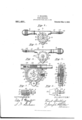
- Figure 1 is a face view of my improved speed indicator.
- Fig. 2 is a back view of the speed indicator.
- Fig. 3 is an enlarged detail sectional view, showing the interior construction of the indicator looking toward the back.
- Fig. 4 is an enlarged transverse sectional view taken on line 4 4 of Fig. 1 through the indicator.
- Fig. 5 is an enlarged detail sectional view looking at the underside of the spring latch, and
- Fig. 6 is an enlarged detail view looking at the inner face of the spring latch.
- a indicates the frame
- b the handle
- c the spindle
- d the worm gear
- e the rotatable latch
- g the setback wheel
- h the front fixed indicating disk
- a' the rotatable front pointer
- 7c the back iixed indicating disk
- Z the rotatable back pointer of my improved speed indicator.
- the frame a has a longitudinal bore 7 for the spindle c intersecting a circular recess 8 which extends in from the face ot the trame and has a central hole 9 which extends through the back 10 of the frame for the hub of the worm gear (Z, a forwardly-extending boss 11 in which is a radial hole 12 for the latch f, and a downwardly-extending portion 13 recessed in the face for the set-back wheel g, as shown in Figs. 3 and 4.
- the handle b is secured to the rear end of the frame ct in the usual way or may be formed integral with the frame.
- the spindle c has the worm 14 on its inner end, a sleeve 15 having a pointed end 16 trictionally secured to its outer end and is rotatably secured in the bore 7 by a screw in the frame a engaging with a circumferential groove in the spindle, as shown in Fig. 3.
- the worm gear Z meshes with the worm 14 on the spindle c and is in the form ot a tlat disk having a central hub 17 which extends equally on both sides of the gear and the length of which equals the thickness of the frame a.
- the rear end of the hub 17 is rotatably supported in the hole 9 in the back 10 ot the frame a, as shown in Fig. 4.
- a stud 18 is secured to the tace ot the worm gear Z in a position to engage with the latch f, as shown in Figs. 3 and 5.
- the rotatable indicating disk e has a toothed or milled edge, a central circular cavity 19 for a spring washer 20 merging into a central hole 21 for the forward end of the worm gear hub 17, the outer circular stepped portion 22 for the front fixed indieating disk 7Ly and the inner circular stepped portion 23.
- a disk 24 having a series of fifty V-shaped notches 25 in its periphery is secured to the inner face of the disk c, as shown in Fig. 4, or may be formed integral with the disk c.
- the latch f is in the form of a pin having a flattened tace 26 adapted to engage with the inner face of the indicating disk e and hold the latch from turning, a V-shaped inner end 27 adapted to engage with the if-shaped notches 25 in the periphery ot the disk 2li, a l/-shaped shoulder 2S on the back, and a collar 29 adjacent the inner end ot the latch.
- a screw-threaded ring 3 is screwed into the end ot the boss 11 and a coiled spring 31 is placed on the latch intermediate the collar 29 on the latch and the ring 230, shown in Fig. 3. i
- the set-back wheel g has a toothed or milled edge and is rotatably secured to the portion 13 ot' the trame a by a screw 32 in a position tor the edge on the periphery ot the wheel to engage with the toothed or milled edge or periphery of the indicating disk e, as shown in Figs. 3 and 4.
- the front iixed indicating disk 7i has central opening t'or the raised central portion of the disk e, and is recessed into the tace of the trame ci tlush with the surface ot the trame where it is held by a screw or other means.
- This disk has inner and outer graduations on its tace, as shown in lfig. 1.
- the iront pointer z' is secured to the front end otl the worin gear hub 17 by a screw 33 which forces the pointer against the spring washer 20, thereby forcing the indicating disk c into frictional Contact with the worm gear CZ, as shown in Fig. L1-.
- the back fixed indicating disk it' has a central opening ⁇ and is recessed into the back 10 of the trame flush with the surt'ace or" the frame, where it is held by a screw or other means.
- This disk has outer graduations on its t'ace (as shown in Fig. 2) corresponding ⁇ to the outer graduations on the disk z.
- the back pointer Z is secured to the back end of the worm gear hub 17 by a screw 33, as shown in F la Villien in use the indicating ⁇ disk e is held normally from rotating by the V-shaped end 2T of the latch f' engaging with a ll-shaped notch 25 in the disk 2a, as shown in liig. G.
- the pointers revolve in the direction o1 the arrows, as shown in Figs. 1 and ⁇ When the worm gear Z completes one revolution the pointers have indicated one hundred revolutions ot the spindle c.
- the stud 18 on the worm gear d now engages with the lf-shaped shoulder' 28 on the latch ji and moves the latch outward against the tension ot ⁇ the sprintf' 31, releasing the indicating disk c.
- the i'rictional contact of the worm gear Z on the disk e moves the disk c one notch or one-tittieth of a revolution, when the stud 18 passing by the latch releases the latch and allows the same to engage with the next notch in the periphery oit the disk 2a. rlhe reading is now one hundred revolutions ot the spindle.
- the latch f acting to release and engage the disk e t'or each one hundred revolutions ot the spindle or until the spindle has revolved ive thousand times, when the indicator will repeat.
- the indicating disk e may be easily and quickly set back at any time by revolving the set-back wheel (j in either direction. the wheel eing placed in a convenient position :tor the tinger or thumb ot the operator to engage with the toothed or milled edge otl the wheel.
- Patentz-e 1. ,ln a speed indicator, a spindle, a worm on the spindle, a w rin gear meshing with the worm, an indicating disk, and me ns operatively connected with the indicating disk, whereby the indicating disk may be revolved by hand independent et" the worm or worm gear.
- a speed indicator In a speed indicator, a spindle, a worm on the spindle, a worin gear meshing with the worm, an indicating disk, means tor holdingthe indicating disk in lirictional contact with the worm gear, a disk having a series ot notches in its periphery secured to the indicatingl disk, a spring actuated latch adapted to engage with the notches in the periphery ot the disk, and means on thel worm gear adapted to operate the spring latch, whereby an intermittent rotary movement is given to the indicating disk.
- a speed indicator in a speed indicator, a trame, a spindle rotatably supported in the trame, a worm on the spindle, a worm gear meshing with the worm, an indicating oisk having a mille l edge, means for htndin.4 the indicating disk in trictional contact 1th the worm gear, a wheel having a milled edge rotatably secured to the traine in a position for the periphery of the wheel to engage with the periliihery of the indicating disk, whereby the indicating disk may be revolved independent ot the ".vorm gear by turning the wheel.
- a speed indicator a traine, a spindle rotatably supported in the trame, a worm on the spindle, a worin gear meshing with the worm, an indicating;I disk, means 'tor holdingl the indicating disk in trictional contact with the worm gear, a disk having a series ot vi-shaped notches in its periphery secured to the indicating disk, a spring actuated latch reciprocally supported in the traine and having itt-shaped end adapted to engage with the lJ-shaped notches in the pernahery ot the disk, and a stud on the worm gear adapted to engage with the latch, whereby an intermittent rotary movement is given to the indicating disk.
- a speed indicator a trame, a spindle rotatably supported in the frame, a worin on the spindle, a worm gear meshing with the worm, an indicating disk on the worm gear having a milled edge, means for holding the indicating disk in rictional contact with the worm gear, a disk having a series ot notches in its periphery secured to or formed integral with the indicating disk, a spring actuated latch in the frame adapted to engage with the notches in the periphery ot the disk, a stud on the worm gear adapted to engage with the latch, and a wheel having a milled edge rotatably secured to the trame in a ⁇ position to extend beyond the frame and for the periphery of the wheel to engage with the periphery of the indicating' disk, whereby an intermittent rotary movement is given to the indicating disk and the indicating disk may be rotated by the milled wheel.
- a speed indicator in a speed indicator, a frame, a spindle rotatably secured in the frame, a worm on the spindle, a worin gear in the frame meshing with the worm, a. hub on the worin gear rotatably supported in the back ot the frame and extending from the back to the frontot the frame, an indicating disk on the worm gear, means tor holding the indicating disk in trictionai contact with the worm gear, a disk having a series ot notches in its periphery secured to the indicating disk, a spring actuated latch in the trame adapted to engage with the notches in the periphery of the disk, a stud on the worm gear adapted to engage with the latch, a.
- a speed indicator a spindle, a Worm on the spindle, a worm gear meshing with the worm, a. rotatable indicating disk, a front ixed indicating disk, a front pointer secured to the hub of the worm gear, a back fixed indicating disk, a back pointer secured to the back hub of the worm gear, and means operatively connected with the rotatable indicating disk, whereby the said disk may be revolved by hand independent of the worm or worm gear.
- a speed indicator the combination ont the following instrumentalities; a trame a, a handle Z) on the frame, a spindle c rotatably supported in the frame and having a worm 14C, a worm gear d in the frame meshing with the worm 14e, a rotatable indicating disk e on the worm gear, a disk 24e havi ig a series of notches 25 25 in its periphery secured to the indicating disk e, means for holding the indicating disk e in rictio-nal contact with the worm gear cl, a spring actuated latch f reciprocally supported in the frame in a position to engage with the notches 25 25 in the periphery of the disk 24, a shoulder 28 on the latch, a stud 18 on the worm gear Z in a position to engage with the shoulder 2S on the latch, a set back wheel 7 rotatably secured to the trame in a position for the periphery of the set back wheel
Landscapes
- Physics & Mathematics (AREA)
- General Physics & Mathematics (AREA)
- Engineering & Computer Science (AREA)
- Theoretical Computer Science (AREA)
- A Measuring Device Byusing Mechanical Method (AREA)
Description
F. SPALDING. SPEED INDIGATR.
APPLICATION FILED APB.15, 1908.
Patented Mar. 8, 1910.
SATEE @FFIQFL FRANK SPALDING, 0F PROVIDENCE, RHODE ISLAND, ASSIGNOR TO :EROI/VN & SHARPE MANUFACTURING COMPANY, OF PROVIDENCE, RHODE ISLAND.
SPEED-INDICATOR.
T o all whom it may concern:
Be it known that I, FRANK SPALDING, a citizen of the United States, residing at Providence, in the county of Providence and State of Rhode Island, have invented a new and useful Improvement in Speed -Indicators, of which the following is a specification.
lThis invention has reference to an improvement in instruments used for measuring or recording the speed of revolving shafts and more particularly to an improvement in speed indicators adapted to record the revolutions of a shaft from one to tive thousand revolutions.
In speed indicators as heretofore constructed (having revolving indicating` disks) the means for intermittently holding one of the disks, usually, consists of an external spring linger engaging with the notches in the disk. These spring fingers are liable to get bent or broken, thereby ruining the utility ot the indicator, also the means used for turning back the disks are generally crude in construction and diiiicult to manipulate.
The object of my invention is to improve the construction of a speed indicator, whereby the means for intermittently holding the revolving indicating disks are protected from injury and strengthened in construction and the indicator provided with means for turning back the disk which can be easily and quickly manipulated by the operator.
My invention consists in the peculiar and novel construction of a speed indicator having an internal spring actuated latch for intermittently holding the revolving indicating disk, a protruding wheel engaging with the periphery of the indicating disk for setting back the disk, and other details of construction as will be more fully set forth hereinafter and claimed.
Figure 1 is a face view of my improved speed indicator. Fig. 2 is a back view of the speed indicator. Fig. 3 is an enlarged detail sectional view, showing the interior construction of the indicator looking toward the back. Fig. 4 is an enlarged transverse sectional view taken on line 4 4 of Fig. 1 through the indicator. Fig. 5 is an enlarged detail sectional view looking at the underside of the spring latch, and Fig. 6 is an enlarged detail view looking at the inner face of the spring latch.
Specification of Letters Patent.
Application filed April 15, 1908.
Patented Mar. 8, 1910.
serial No. 427,246.
In the drawings, a, indicates the frame, b the handle, c the spindle, d the worm gear, e the rotatable latch, g the setback wheel, h the front fixed indicating disk, a' the rotatable front pointer, 7c the back iixed indicating disk, and Z the rotatable back pointer of my improved speed indicator.
The frame a has a longitudinal bore 7 for the spindle c intersecting a circular recess 8 which extends in from the face ot the trame and has a central hole 9 which extends through the back 10 of the frame for the hub of the worm gear (Z, a forwardly-extending boss 11 in which is a radial hole 12 for the latch f, and a downwardly-extending portion 13 recessed in the face for the set-back wheel g, as shown in Figs. 3 and 4.
The handle b is secured to the rear end of the frame ct in the usual way or may be formed integral with the frame.
The spindle c has the worm 14 on its inner end, a sleeve 15 having a pointed end 16 trictionally secured to its outer end and is rotatably secured in the bore 7 by a screw in the frame a engaging with a circumferential groove in the spindle, as shown in Fig. 3.
The worm gear Z meshes with the worm 14 on the spindle c and is in the form ot a tlat disk having a central hub 17 which extends equally on both sides of the gear and the length of which equals the thickness of the frame a. The rear end of the hub 17 is rotatably supported in the hole 9 in the back 10 ot the frame a, as shown in Fig. 4. A stud 18 is secured to the tace ot the worm gear Z in a position to engage with the latch f, as shown in Figs. 3 and 5.
The rotatable indicating disk e has a toothed or milled edge, a central circular cavity 19 for a spring washer 20 merging into a central hole 21 for the forward end of the worm gear hub 17, the outer circular stepped portion 22 for the front fixed indieating disk 7Ly and the inner circular stepped portion 23. A disk 24 having a series of fifty V-shaped notches 25 in its periphery is secured to the inner face of the disk c, as shown in Fig. 4, or may be formed integral with the disk c.
The latch f is in the form of a pin having a flattened tace 26 adapted to engage with the inner face of the indicating disk e and hold the latch from turning, a V-shaped inner end 27 adapted to engage with the if-shaped notches 25 in the periphery ot the disk 2li, a l/-shaped shoulder 2S on the back, and a collar 29 adjacent the inner end ot the latch. A screw-threaded ring 3 is screwed into the end ot the boss 11 and a coiled spring 31 is placed on the latch intermediate the collar 29 on the latch and the ring 230, shown in Fig. 3. i
rthe set-back wheel g has a toothed or milled edge and is rotatably secured to the portion 13 ot' the trame a by a screw 32 in a position tor the edge on the periphery ot the wheel to engage with the toothed or milled edge or periphery of the indicating disk e, as shown in Figs. 3 and 4.
The front iixed indicating disk 7i has central opening t'or the raised central portion of the disk e, and is recessed into the tace of the trame ci tlush with the surface ot the trame where it is held by a screw or other means. This disk has inner and outer graduations on its tace, as shown in lfig. 1.
The iront pointer z' is secured to the front end otl the worin gear hub 17 by a screw 33 which forces the pointer against the spring washer 20, thereby forcing the indicating disk c into frictional Contact with the worm gear CZ, as shown in Fig. L1-.
The back fixed indicating disk it' has a central opening` and is recessed into the back 10 of the trame flush with the surt'ace or" the frame, where it is held by a screw or other means. This disk has outer graduations on its t'ace (as shown in Fig. 2) corresponding` to the outer graduations on the disk z.
The back pointer Z is secured to the back end of the worm gear hub 17 by a screw 33, as shown in F la Villien in use the indicating` disk e is held normally from rotating by the V-shaped end 2T of the latch f' engaging with a ll-shaped notch 25 in the disk 2a, as shown in liig. G. The pointers revolve in the direction o1 the arrows, as shown in Figs. 1 and `When the worm gear Z completes one revolution the pointers have indicated one hundred revolutions ot the spindle c. The stud 18 on the worm gear d now engages with the lf-shaped shoulder' 28 on the latch ji and moves the latch outward against the tension ot` the sprintf' 31, releasing the indicating disk c. The i'rictional contact of the worm gear Z on the disk e moves the disk c one notch or one-tittieth of a revolution, when the stud 18 passing by the latch releases the latch and allows the same to engage with the next notch in the periphery oit the disk 2a. rlhe reading is now one hundred revolutions ot the spindle. As the spindle continues to revolve these operations are repeated, the latch f acting to release and engage the disk e t'or each one hundred revolutions ot the spindle or until the spindle has revolved ive thousand times, when the indicator will repeat. The indicating disk e may be easily and quickly set back at any time by revolving the set-back wheel (j in either direction. the wheel eing placed in a convenient position :tor the tinger or thumb ot the operator to engage with the toothed or milled edge otl the wheel.
Having thus described my invention, vI claim as new and desire to secure b v lietters Patentz-e 1. ,ln a speed indicator, a spindle, a worm on the spindle, a w rin gear meshing with the worm, an indicating disk, and me ns operatively connected with the indicating disk, whereby the indicating disk may be revolved by hand independent et" the worm or worm gear.
i). in a speed indicator, a spindle, a worm on the spindle, a worin gear meshing with the worin, an indicating disk, means tor holding the indicating disk in trictional con tact with the worm gear, and a wheel oper atively connected with the indicating disk, v-.fhereby the ii'idicating disk may be revolved by hand independent of the worm gear.
In a speed indicator, a spindle, a worm on the spindle, a worin gear meshing with the worm, an indicating disk, means tor holdingthe indicating disk in lirictional contact with the worm gear, a disk having a series ot notches in its periphery secured to the indicatingl disk, a spring actuated latch adapted to engage with the notches in the periphery ot the disk, and means on thel worm gear adapted to operate the spring latch, whereby an intermittent rotary movement is given to the indicating disk.
et. in a speed indicator, a trame, a spindle rotatably supported in the trame, a worm on the spindle, a worm gear meshing with the worm, an indicating oisk having a mille l edge, means for htndin.4 the indicating disk in trictional contact 1th the worm gear, a wheel having a milled edge rotatably secured to the traine in a position for the periphery of the wheel to engage with the periliihery of the indicating disk, whereby the indicating disk may be revolved independent ot the ".vorm gear by turning the wheel.
5. ln a speed indicator, a traine, a spindle rotatably supported in the trame, a worm on the spindle, a worin gear meshing with the worm, an indicating;I disk, means 'tor holdingl the indicating disk in trictional contact with the worm gear, a disk having a series ot vi-shaped notches in its periphery secured to the indicating disk, a spring actuated latch reciprocally supported in the traine and having itt-shaped end adapted to engage with the lJ-shaped notches in the pernahery ot the disk, and a stud on the worm gear adapted to engage with the latch, whereby an intermittent rotary movement is given to the indicating disk.
6. ln a speed indicator, a trame, a spindle rotatably supported in the frame, a worin on the spindle, a worm gear meshing with the worm, an indicating disk on the worm gear having a milled edge, means for holding the indicating disk in rictional contact with the worm gear, a disk having a series ot notches in its periphery secured to or formed integral with the indicating disk, a spring actuated latch in the frame adapted to engage with the notches in the periphery ot the disk, a stud on the worm gear adapted to engage with the latch, and a wheel having a milled edge rotatably secured to the trame in a `position to extend beyond the frame and for the periphery of the wheel to engage with the periphery of the indicating' disk, whereby an intermittent rotary movement is given to the indicating disk and the indicating disk may be rotated by the milled wheel.
7. in a speed indicator, a frame, a spindle rotatably secured in the frame, a worm on the spindle, a worin gear in the frame meshing with the worm, a. hub on the worin gear rotatably supported in the back ot the frame and extending from the back to the frontot the frame, an indicating disk on the worm gear, means tor holding the indicating disk in trictionai contact with the worm gear, a disk having a series ot notches in its periphery secured to the indicating disk, a spring actuated latch in the trame adapted to engage with the notches in the periphery of the disk, a stud on the worm gear adapted to engage with the latch, a. wheel rotatably secured to the frame in a? position for the periphery of the wheel to engage with the periphery of the indicating disk, tixed indicating disks on the front and back otl the `rame, and pointers secured to each end of the worm gear hub in a position to extend over the ixed indicating disks.
8. In a speed indicator, a spindle, a Worm on the spindle, a worm gear meshing with the worm, a. rotatable indicating disk, a front ixed indicating disk, a front pointer secured to the hub of the worm gear, a back fixed indicating disk, a back pointer secured to the back hub of the worm gear, and means operatively connected with the rotatable indicating disk, whereby the said disk may be revolved by hand independent of the worm or worm gear.
9. In a speed indicator, the combination ont the following instrumentalities; a trame a, a handle Z) on the frame, a spindle c rotatably supported in the frame and having a worm 14C, a worm gear d in the frame meshing with the worm 14e, a rotatable indicating disk e on the worm gear, a disk 24e havi ig a series of notches 25 25 in its periphery secured to the indicating disk e, means for holding the indicating disk e in rictio-nal contact with the worm gear cl, a spring actuated latch f reciprocally supported in the frame in a position to engage with the notches 25 25 in the periphery of the disk 24, a shoulder 28 on the latch, a stud 18 on the worm gear Z in a position to engage with the shoulder 2S on the latch, a set back wheel 7 rotatably secured to the trame in a position for the periphery of the set back wheel g` to engage with the periphery of the indicating` disk e, a front ixed indicating disk 7L, a front pointer z' secured to the hub of the worm gear cl, a back fixed indicating disk 7c, and a back pointer Z secured to the hub of the worm gear CZ, as described.
In testimony whereof I have signed my name to this specification in the presence of two subscribing witnesses.
FRANK SPALDNG. litnesses:
ADA E. HAGERTY, J. A. MiLLER.
Priority Applications (1)
| Application Number | Priority Date | Filing Date | Title |
|---|---|---|---|
| US42724608A US951491A (en) | 1908-04-15 | 1908-04-15 | Speed-indicator. |
Applications Claiming Priority (1)
| Application Number | Priority Date | Filing Date | Title |
|---|---|---|---|
| US42724608A US951491A (en) | 1908-04-15 | 1908-04-15 | Speed-indicator. |
Publications (1)
| Publication Number | Publication Date |
|---|---|
| US951491A true US951491A (en) | 1910-03-08 |
Family
ID=3019902
Family Applications (1)
| Application Number | Title | Priority Date | Filing Date |
|---|---|---|---|
| US42724608A Expired - Lifetime US951491A (en) | 1908-04-15 | 1908-04-15 | Speed-indicator. |
Country Status (1)
| Country | Link |
|---|---|
| US (1) | US951491A (en) |
-
1908
- 1908-04-15 US US42724608A patent/US951491A/en not_active Expired - Lifetime
Similar Documents
| Publication | Publication Date | Title |
|---|---|---|
| US1021384A (en) | Micrometer-gage. | |
| US1065744A (en) | Micrometer-gage. | |
| US1357323A (en) | Measuring instrument | |
| US1006924A (en) | Test-indicator. | |
| US435012A (en) | Speed-measure | |
| US2487844A (en) | Indicating square | |
| US1121632A (en) | Micrometer-calipers. | |
| US990655A (en) | Micrometer-calipers. | |
| US2428828A (en) | Tachometer | |
| US1380580A (en) | Surface and center indicator | |
| US1235478A (en) | Micrometer-calipers. | |
| US790665A (en) | Micrometer-calipers. | |
| US1210051A (en) | Direct-reading micrometer-caliper. | |
| US1217850A (en) | Micrometer-gage. | |
| US826971A (en) | Truing-up indicator. | |
| US1095745A (en) | Micrometer-caliper. | |
| US1526115A (en) | Measuring and indicating instrumentalities | |
| US1503353A (en) | Recording pressure gauge, indicator, and other measuring instrument | |
| US2717451A (en) | Depth micrometer | |
| US520201A (en) | Micrometer-indicator | |
| US843361A (en) | Speed-indicator. | |
| US391067A (en) | Thomas philop owen | |
| US1518244A (en) | Speed or like indicating device | |
| US991839A (en) | Micrometer-protractor. | |
| US801205A (en) | Register and mechanism therefor. |