US9513510B1 - Alignment material for liquid crystal lens and liquid crystal lens system - Google Patents
Alignment material for liquid crystal lens and liquid crystal lens system Download PDFInfo
- Publication number
- US9513510B1 US9513510B1 US14/922,992 US201514922992A US9513510B1 US 9513510 B1 US9513510 B1 US 9513510B1 US 201514922992 A US201514922992 A US 201514922992A US 9513510 B1 US9513510 B1 US 9513510B1
- Authority
- US
- United States
- Prior art keywords
- alignment material
- lens
- substrates
- liquid crystal
- polymer
- Prior art date
- Legal status (The legal status is an assumption and is not a legal conclusion. Google has not performed a legal analysis and makes no representation as to the accuracy of the status listed.)
- Expired - Fee Related
Links
- 239000004973 liquid crystal related substance Substances 0.000 title claims abstract description 102
- 239000000463 material Substances 0.000 title claims abstract description 88
- 239000000178 monomer Substances 0.000 claims abstract description 86
- 229920001577 copolymer Polymers 0.000 claims abstract description 41
- -1 alkyl methacrylate Chemical compound 0.000 claims abstract description 33
- 239000000758 substrate Substances 0.000 claims description 91
- 238000000034 method Methods 0.000 claims description 32
- 206010034972 Photosensitivity reaction Diseases 0.000 claims description 19
- 230000036211 photosensitivity Effects 0.000 claims description 19
- 230000008569 process Effects 0.000 claims description 19
- 239000002245 particle Substances 0.000 claims description 12
- 238000000151 deposition Methods 0.000 claims description 10
- 239000011521 glass Substances 0.000 claims description 10
- 239000002904 solvent Substances 0.000 claims description 10
- 125000004169 (C1-C6) alkyl group Chemical group 0.000 claims description 7
- 125000004417 unsaturated alkyl group Chemical group 0.000 claims description 7
- 229920006395 saturated elastomer Polymers 0.000 claims description 6
- 239000003292 glue Substances 0.000 claims description 3
- 125000006850 spacer group Chemical group 0.000 claims description 3
- 125000000217 alkyl group Chemical group 0.000 claims 1
- 230000010287 polarization Effects 0.000 abstract description 17
- 238000004519 manufacturing process Methods 0.000 abstract description 12
- 239000011159 matrix material Substances 0.000 description 10
- 230000003287 optical effect Effects 0.000 description 7
- 0 *OC.CC.CC.CC.CCC(C)(C)C(=O)OC1=CC=C(C=O)C=C1.CCC(C)C1=CC=C(C(=O)OC2=CC=C(C=O)C=C2)C=C1.CCOC(=O)C(C)(C)CC Chemical compound *OC.CC.CC.CC.CCC(C)(C)C(=O)OC1=CC=C(C=O)C=C1.CCC(C)C1=CC=C(C(=O)OC2=CC=C(C=O)C=C2)C=C1.CCOC(=O)C(C)(C)CC 0.000 description 5
- 238000009826 distribution Methods 0.000 description 5
- 239000000126 substance Substances 0.000 description 5
- 230000008859 change Effects 0.000 description 2
- 230000001419 dependent effect Effects 0.000 description 2
- 230000008021 deposition Effects 0.000 description 2
- 229920000642 polymer Polymers 0.000 description 2
- DKPFZGUDAPQIHT-UHFFFAOYSA-N Butyl acetate Natural products CCCCOC(C)=O DKPFZGUDAPQIHT-UHFFFAOYSA-N 0.000 description 1
- AZDPLRQUJYYNJC-UHFFFAOYSA-N CC#COC(=O)C(C)(C)CC.CCC(C)(C)C(=O)OC1=CC=C(C=O)C=C1OC.CCC(C)C1=CC=C(C(=O)OC2=CC=C(C=O)C=C2)C=C1.CCCCCCCCCCCCCCCCOC(=O)C(C)(C)CC.CCCCOC(=O)C(C)(C)CC Chemical compound CC#COC(=O)C(C)(C)CC.CCC(C)(C)C(=O)OC1=CC=C(C=O)C=C1OC.CCC(C)C1=CC=C(C(=O)OC2=CC=C(C=O)C=C2)C=C1.CCCCCCCCCCCCCCCCOC(=O)C(C)(C)CC.CCCCOC(=O)C(C)(C)CC AZDPLRQUJYYNJC-UHFFFAOYSA-N 0.000 description 1
- IOUSZFHURUNRKK-UHFFFAOYSA-N CC.CC.CC.CCC(C)C1=CC=C(C(=O)OC2=CC=C(C=O)C=C2)C=C1.CCC(C)C1=CC=C(C(=O)OC2=CC=C(C=O)C=C2)C=C1 Chemical compound CC.CC.CC.CCC(C)C1=CC=C(C(=O)OC2=CC=C(C=O)C=C2)C=C1.CCC(C)C1=CC=C(C(=O)OC2=CC=C(C=O)C=C2)C=C1 IOUSZFHURUNRKK-UHFFFAOYSA-N 0.000 description 1
- OWKRTTGNBBKSFW-UHFFFAOYSA-N CCC(C)(C)C(=O)OC.CCC(C)(C)C(=O)OC1=CC=C(C=O)C=C1OC.CCC(C)C1=CC=C(C(=O)OC2=CC=C(C=O)C=C2)C=C1.CCCCCCCCCCCCCCCCOC(=O)C(C)(C)CC.CCCCOC(=O)C(C)(C)CC Chemical compound CCC(C)(C)C(=O)OC.CCC(C)(C)C(=O)OC1=CC=C(C=O)C=C1OC.CCC(C)C1=CC=C(C(=O)OC2=CC=C(C=O)C=C2)C=C1.CCCCCCCCCCCCCCCCOC(=O)C(C)(C)CC.CCCCOC(=O)C(C)(C)CC OWKRTTGNBBKSFW-UHFFFAOYSA-N 0.000 description 1
- FWXLMMAQHAYYON-UHFFFAOYSA-N CCC(C)(C)C(=O)OC.CCCCCCCCCCCCCCCCOC(=O)C(C)(C)CC.CCCCOC(=O)C(C)(C)CC Chemical compound CCC(C)(C)C(=O)OC.CCCCCCCCCCCCCCCCOC(=O)C(C)(C)CC.CCCCOC(=O)C(C)(C)CC FWXLMMAQHAYYON-UHFFFAOYSA-N 0.000 description 1
- YKDCATRNPVJHMY-UHFFFAOYSA-N CCOC(=O)C(C)(C)CC Chemical compound CCOC(=O)C(C)(C)CC YKDCATRNPVJHMY-UHFFFAOYSA-N 0.000 description 1
- 238000000862 absorption spectrum Methods 0.000 description 1
- 230000004075 alteration Effects 0.000 description 1
- 238000013459 approach Methods 0.000 description 1
- 230000007423 decrease Effects 0.000 description 1
- 238000011161 development Methods 0.000 description 1
- 231100000673 dose–response relationship Toxicity 0.000 description 1
- FUZZWVXGSFPDMH-UHFFFAOYSA-N hexanoic acid Chemical compound CCCCCC(O)=O FUZZWVXGSFPDMH-UHFFFAOYSA-N 0.000 description 1
- 230000003993 interaction Effects 0.000 description 1
- 238000005259 measurement Methods 0.000 description 1
- 238000000386 microscopy Methods 0.000 description 1
- 238000012986 modification Methods 0.000 description 1
- 230000004048 modification Effects 0.000 description 1
- 238000012545 processing Methods 0.000 description 1
- 230000035945 sensitivity Effects 0.000 description 1
- 230000003595 spectral effect Effects 0.000 description 1
Images


Classifications
-
- G—PHYSICS
- G02—OPTICS
- G02F—OPTICAL DEVICES OR ARRANGEMENTS FOR THE CONTROL OF LIGHT BY MODIFICATION OF THE OPTICAL PROPERTIES OF THE MEDIA OF THE ELEMENTS INVOLVED THEREIN; NON-LINEAR OPTICS; FREQUENCY-CHANGING OF LIGHT; OPTICAL LOGIC ELEMENTS; OPTICAL ANALOGUE/DIGITAL CONVERTERS
- G02F1/00—Devices or arrangements for the control of the intensity, colour, phase, polarisation or direction of light arriving from an independent light source, e.g. switching, gating or modulating; Non-linear optics
- G02F1/29—Devices or arrangements for the control of the intensity, colour, phase, polarisation or direction of light arriving from an independent light source, e.g. switching, gating or modulating; Non-linear optics for the control of the position or the direction of light beams, i.e. deflection
-
- G—PHYSICS
- G02—OPTICS
- G02F—OPTICAL DEVICES OR ARRANGEMENTS FOR THE CONTROL OF LIGHT BY MODIFICATION OF THE OPTICAL PROPERTIES OF THE MEDIA OF THE ELEMENTS INVOLVED THEREIN; NON-LINEAR OPTICS; FREQUENCY-CHANGING OF LIGHT; OPTICAL LOGIC ELEMENTS; OPTICAL ANALOGUE/DIGITAL CONVERTERS
- G02F1/00—Devices or arrangements for the control of the intensity, colour, phase, polarisation or direction of light arriving from an independent light source, e.g. switching, gating or modulating; Non-linear optics
- G02F1/01—Devices or arrangements for the control of the intensity, colour, phase, polarisation or direction of light arriving from an independent light source, e.g. switching, gating or modulating; Non-linear optics for the control of the intensity, phase, polarisation or colour
- G02F1/13—Devices or arrangements for the control of the intensity, colour, phase, polarisation or direction of light arriving from an independent light source, e.g. switching, gating or modulating; Non-linear optics for the control of the intensity, phase, polarisation or colour based on liquid crystals, e.g. single liquid crystal display cells
- G02F1/133—Constructional arrangements; Operation of liquid crystal cells; Circuit arrangements
- G02F1/1333—Constructional arrangements; Manufacturing methods
- G02F1/1337—Surface-induced orientation of the liquid crystal molecules, e.g. by alignment layers
- G02F1/133711—Surface-induced orientation of the liquid crystal molecules, e.g. by alignment layers by organic films, e.g. polymeric films
-
- G—PHYSICS
- G02—OPTICS
- G02F—OPTICAL DEVICES OR ARRANGEMENTS FOR THE CONTROL OF LIGHT BY MODIFICATION OF THE OPTICAL PROPERTIES OF THE MEDIA OF THE ELEMENTS INVOLVED THEREIN; NON-LINEAR OPTICS; FREQUENCY-CHANGING OF LIGHT; OPTICAL LOGIC ELEMENTS; OPTICAL ANALOGUE/DIGITAL CONVERTERS
- G02F1/00—Devices or arrangements for the control of the intensity, colour, phase, polarisation or direction of light arriving from an independent light source, e.g. switching, gating or modulating; Non-linear optics
- G02F1/01—Devices or arrangements for the control of the intensity, colour, phase, polarisation or direction of light arriving from an independent light source, e.g. switching, gating or modulating; Non-linear optics for the control of the intensity, phase, polarisation or colour
- G02F1/13—Devices or arrangements for the control of the intensity, colour, phase, polarisation or direction of light arriving from an independent light source, e.g. switching, gating or modulating; Non-linear optics for the control of the intensity, phase, polarisation or colour based on liquid crystals, e.g. single liquid crystal display cells
- G02F1/133—Constructional arrangements; Operation of liquid crystal cells; Circuit arrangements
- G02F1/1333—Constructional arrangements; Manufacturing methods
- G02F1/1337—Surface-induced orientation of the liquid crystal molecules, e.g. by alignment layers
- G02F1/13378—Surface-induced orientation of the liquid crystal molecules, e.g. by alignment layers by treatment of the surface, e.g. embossing, rubbing or light irradiation
- G02F1/133784—Surface-induced orientation of the liquid crystal molecules, e.g. by alignment layers by treatment of the surface, e.g. embossing, rubbing or light irradiation by rubbing
-
- G—PHYSICS
- G02—OPTICS
- G02F—OPTICAL DEVICES OR ARRANGEMENTS FOR THE CONTROL OF LIGHT BY MODIFICATION OF THE OPTICAL PROPERTIES OF THE MEDIA OF THE ELEMENTS INVOLVED THEREIN; NON-LINEAR OPTICS; FREQUENCY-CHANGING OF LIGHT; OPTICAL LOGIC ELEMENTS; OPTICAL ANALOGUE/DIGITAL CONVERTERS
- G02F1/00—Devices or arrangements for the control of the intensity, colour, phase, polarisation or direction of light arriving from an independent light source, e.g. switching, gating or modulating; Non-linear optics
- G02F1/01—Devices or arrangements for the control of the intensity, colour, phase, polarisation or direction of light arriving from an independent light source, e.g. switching, gating or modulating; Non-linear optics for the control of the intensity, phase, polarisation or colour
- G02F1/13—Devices or arrangements for the control of the intensity, colour, phase, polarisation or direction of light arriving from an independent light source, e.g. switching, gating or modulating; Non-linear optics for the control of the intensity, phase, polarisation or colour based on liquid crystals, e.g. single liquid crystal display cells
- G02F1/133—Constructional arrangements; Operation of liquid crystal cells; Circuit arrangements
- G02F1/1333—Constructional arrangements; Manufacturing methods
- G02F1/1337—Surface-induced orientation of the liquid crystal molecules, e.g. by alignment layers
- G02F1/13378—Surface-induced orientation of the liquid crystal molecules, e.g. by alignment layers by treatment of the surface, e.g. embossing, rubbing or light irradiation
- G02F1/133788—Surface-induced orientation of the liquid crystal molecules, e.g. by alignment layers by treatment of the surface, e.g. embossing, rubbing or light irradiation by light irradiation, e.g. linearly polarised light photo-polymerisation
-
- C—CHEMISTRY; METALLURGY
- C09—DYES; PAINTS; POLISHES; NATURAL RESINS; ADHESIVES; COMPOSITIONS NOT OTHERWISE PROVIDED FOR; APPLICATIONS OF MATERIALS NOT OTHERWISE PROVIDED FOR
- C09K—MATERIALS FOR MISCELLANEOUS APPLICATIONS, NOT PROVIDED FOR ELSEWHERE
- C09K2323/00—Functional layers of liquid crystal optical display excluding electroactive liquid crystal layer characterised by chemical composition
- C09K2323/02—Alignment layer characterised by chemical composition
-
- G—PHYSICS
- G02—OPTICS
- G02F—OPTICAL DEVICES OR ARRANGEMENTS FOR THE CONTROL OF LIGHT BY MODIFICATION OF THE OPTICAL PROPERTIES OF THE MEDIA OF THE ELEMENTS INVOLVED THEREIN; NON-LINEAR OPTICS; FREQUENCY-CHANGING OF LIGHT; OPTICAL LOGIC ELEMENTS; OPTICAL ANALOGUE/DIGITAL CONVERTERS
- G02F1/00—Devices or arrangements for the control of the intensity, colour, phase, polarisation or direction of light arriving from an independent light source, e.g. switching, gating or modulating; Non-linear optics
- G02F1/01—Devices or arrangements for the control of the intensity, colour, phase, polarisation or direction of light arriving from an independent light source, e.g. switching, gating or modulating; Non-linear optics for the control of the intensity, phase, polarisation or colour
- G02F1/13—Devices or arrangements for the control of the intensity, colour, phase, polarisation or direction of light arriving from an independent light source, e.g. switching, gating or modulating; Non-linear optics for the control of the intensity, phase, polarisation or colour based on liquid crystals, e.g. single liquid crystal display cells
- G02F1/133—Constructional arrangements; Operation of liquid crystal cells; Circuit arrangements
- G02F1/1333—Constructional arrangements; Manufacturing methods
- G02F1/133302—Rigid substrates, e.g. inorganic substrates
-
- G—PHYSICS
- G02—OPTICS
- G02F—OPTICAL DEVICES OR ARRANGEMENTS FOR THE CONTROL OF LIGHT BY MODIFICATION OF THE OPTICAL PROPERTIES OF THE MEDIA OF THE ELEMENTS INVOLVED THEREIN; NON-LINEAR OPTICS; FREQUENCY-CHANGING OF LIGHT; OPTICAL LOGIC ELEMENTS; OPTICAL ANALOGUE/DIGITAL CONVERTERS
- G02F1/00—Devices or arrangements for the control of the intensity, colour, phase, polarisation or direction of light arriving from an independent light source, e.g. switching, gating or modulating; Non-linear optics
- G02F1/01—Devices or arrangements for the control of the intensity, colour, phase, polarisation or direction of light arriving from an independent light source, e.g. switching, gating or modulating; Non-linear optics for the control of the intensity, phase, polarisation or colour
- G02F1/13—Devices or arrangements for the control of the intensity, colour, phase, polarisation or direction of light arriving from an independent light source, e.g. switching, gating or modulating; Non-linear optics for the control of the intensity, phase, polarisation or colour based on liquid crystals, e.g. single liquid crystal display cells
- G02F1/133—Constructional arrangements; Operation of liquid crystal cells; Circuit arrangements
- G02F1/1333—Constructional arrangements; Manufacturing methods
- G02F1/1337—Surface-induced orientation of the liquid crystal molecules, e.g. by alignment layers
- G02F1/133711—Surface-induced orientation of the liquid crystal molecules, e.g. by alignment layers by organic films, e.g. polymeric films
- G02F1/133715—Surface-induced orientation of the liquid crystal molecules, e.g. by alignment layers by organic films, e.g. polymeric films by first depositing a monomer
-
- G—PHYSICS
- G02—OPTICS
- G02F—OPTICAL DEVICES OR ARRANGEMENTS FOR THE CONTROL OF LIGHT BY MODIFICATION OF THE OPTICAL PROPERTIES OF THE MEDIA OF THE ELEMENTS INVOLVED THEREIN; NON-LINEAR OPTICS; FREQUENCY-CHANGING OF LIGHT; OPTICAL LOGIC ELEMENTS; OPTICAL ANALOGUE/DIGITAL CONVERTERS
- G02F1/00—Devices or arrangements for the control of the intensity, colour, phase, polarisation or direction of light arriving from an independent light source, e.g. switching, gating or modulating; Non-linear optics
- G02F1/29—Devices or arrangements for the control of the intensity, colour, phase, polarisation or direction of light arriving from an independent light source, e.g. switching, gating or modulating; Non-linear optics for the control of the position or the direction of light beams, i.e. deflection
- G02F1/291—Two-dimensional analogue deflection
-
- G—PHYSICS
- G02—OPTICS
- G02F—OPTICAL DEVICES OR ARRANGEMENTS FOR THE CONTROL OF LIGHT BY MODIFICATION OF THE OPTICAL PROPERTIES OF THE MEDIA OF THE ELEMENTS INVOLVED THEREIN; NON-LINEAR OPTICS; FREQUENCY-CHANGING OF LIGHT; OPTICAL LOGIC ELEMENTS; OPTICAL ANALOGUE/DIGITAL CONVERTERS
- G02F1/00—Devices or arrangements for the control of the intensity, colour, phase, polarisation or direction of light arriving from an independent light source, e.g. switching, gating or modulating; Non-linear optics
- G02F1/29—Devices or arrangements for the control of the intensity, colour, phase, polarisation or direction of light arriving from an independent light source, e.g. switching, gating or modulating; Non-linear optics for the control of the position or the direction of light beams, i.e. deflection
- G02F1/294—Variable focal length devices
-
- G02F2001/133302—
-
- G02F2001/133715—
-
- Y10T428/10—
-
- Y10T428/1005—
Definitions
- This disclosure relates generally to electrically tunable liquid crystal (LC) lens. More specifically, this disclosure relates to an alignment material capable of generating pretilt angles upon exposure to light. Also, this disclosure relates to LC lenses and LC lens systems comprising such alignment material. Moreover, this disclosure relate to a method for making such LC lenses and LC lens systems.
- LC liquid crystal
- a regular LC lens is polarization-dependent.
- two or more LC lenses or sub-lenses are stacked together and mutual orthogonal orientation is attempted.
- Each sub-lens is manufactured separately and special precise mechanics are required in order to achieve a mutual alignment of the optical axes. This constitutes a complicated and challenging process.
- a poor alignment generally induces polarization aberration which affects the quality of image, i.e., image doubling.
- alignment layers More specifically, the alignment material which typically comprises a photo-aligned polymer is staked in layers on a substrate.
- the alignment material is capable of generating pretilt angles (Chung-Yung Lee et al., 2009).
- This disclosure is drawn to an alignment material for a LC lens comprising a co-polymer of a photosensitive monomer and at least one alkyl methacrylate monomer.
- the material allows for the fabrication of a LC lens or LC lens system that is self-aligned and polarization-independent.
- the LC lens or LC lens system of this disclosure has a focal length which may be changed in a low voltage controlled manner, such as for example below about 10V AC.
- the fabrication process of this disclosure allows for a simultaneous fabrication of two orthogonally oriented sub-lenses in a self-aligned manner.
- this disclosure relates to an alignment material for a liquid crystal (LC) lens, comprising a co-polymer of a photosensitive monomer and at least one alkyl methacrylate monomer.
- LC liquid crystal
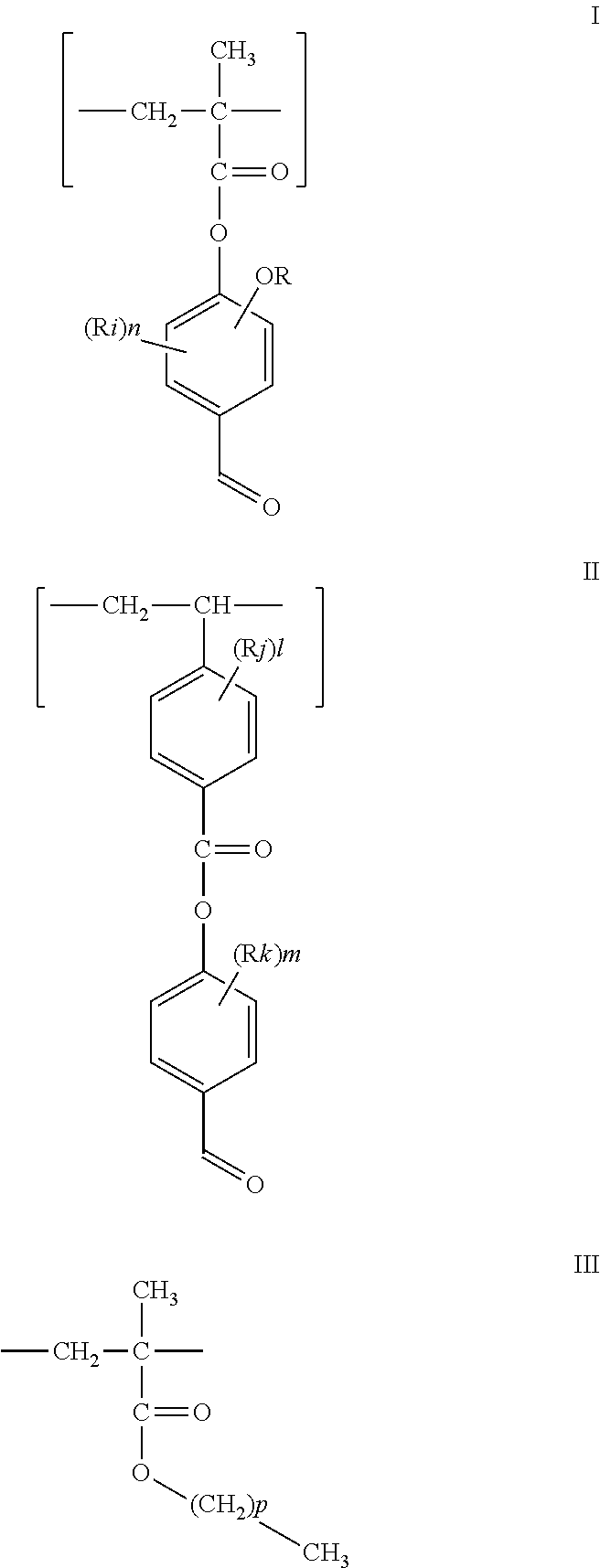
- the photosensitive monomer is of general formula I or II
- the at least one alkyl methacrylate monomer is of general formula III
- R is a C 1 to C 12 linear, branched, saturated and/or unsaturated alkyl group
- Ri, Rj and Rk each independently selected from the group consisting of H and C 1 to C 12 linear, branched, saturated and/or unsaturated alkyl groups
- n is an integer from 0-3
- m and 1 are each independently an integer from 0-4
- p is an integer from 0-30.
- the photosensitive monomer is of general formula IA or IIA
- the at least one alkyl methacrylate monomer is of general formula III
- R is a C 1 to C 6 alkyl group
- Rk is a H or a C 1 to C 6 alkyl group
- m is an integer from 0-2
- p is an integer from 1-20.
- the photosensitive monomer is of formula M or F, and the at least one alkyl methacrylate monomer is selected from formulae VA, PL and PL1
- the co-polymer is of M, VA, PL and PL1 or the co-polymer is of F, VA, PL and PL1.
- the co-polymer is of M, VA, PL and PL1; and wherein M is present in an amount of about 7-17% mol, preferably about 9-15% mol, more preferably about 12% mol; VA is present in an amount of about 2.5-12.5% mol, preferably about 4.5-10.5% mol, more preferably about 7.5% mol; PL is present in an amount of is present in an amount of about 65.5-75.5% mol, preferably about 67.5-73.5% mol, more preferably about 70.5% mol; and PL1 is present in an amount of about 5-15%, preferably about 7-13% mol, more preferably about 10% mol.
- the co-polymer is of F, VA, PL and PL1; and wherein F is present in an amount of about 0.5-9% mol, preferably 2-8% mol, more preferably about 5% mol; VA is present in an amount of about 3-15.5% mol, preferably about 4.5-10.5% mol, more preferably about 7.5% mol; PL is present in an amount of about 73-82.5% mol, preferably about 74.5-80.5% mol, more preferably 77.5; and PL1 is present in an amount of about 5.5-15% mol, preferably about 7-13% mol, more preferably about 10% mol.
- this disclosure relates to a liquid crystal (LC) lens comprising: a first planar substrate having on a surface thereof a layer of first alignment material comprising a co-polymer of a first photosensitive monomer and at least one alkyl methacrylate monomer; and a second planar substrate having on a surface thereof a layer of second alignment material comprising a co-polymer of a second photosensitive monomer and at least one alkyl methacrylate monomer, wherein the first and second substrates are assembled in parallel configuration such that the layers of alignment material face each other and are spaced apart, and wherein the first and second photosensitive monomers are of different photosensitivities, and wherein particles of the first alignment material have a pretilt angle gradient that is different from a pretilt angle gradient of the second alignment material.
- LC liquid crystal
- the lens further comprises a spacer between the layers of alignment material.
- the substrates are attached together at contours thereof, optionally the attachment is made with UV glue.
- the substrates are glass substrates.
- the lens further comprises an electrode mounted on a surface of at least one of the substrate.
- the lens has a focal length which may be controllably changed at a voltage between about 1-10V AC, preferably about 1-5V AC.
- this disclosure relates to a liquid crystal (LC) lens system comprising: first planar substrates each having on both surfaces thereof a layer of first alignment material comprising a co-polymer of a first photosensitive monomer and at least one alkyl methacrylate monomer; and second planar substrates each having on both surfaces thereof a layer of second alignment material comprising a co-polymer of a second photosensitive monomer and at least one alkyl methacrylate monomer, wherein the substrates are assembled in parallel configuration such that a layer of first alignment material and a layer of second alignment material face each other and are spaced apart, and wherein the first and second photosensitive monomers are of different photosensitivities, and wherein particles of the first alignment material have a pretilt angle gradient that is different from a pretilt angle gradient of the second alignment material.
- first alignment material comprising a co-polymer of a first photosensitive monomer and at least one alkyl methacrylate monomer
- second planar substrates each having on both surfaces
- a pretilt angle gradient in the first alignment material on the first substrates is identical, and a pretilt angle gradient in the second alignment material on the second substrates is identical.
- this disclosure relates to a method for making an electrically tunable liquid crystal (LC) lens, comprising: (a) providing a first planar substrate and a second planar substrate; (b) depositing on a surface of the first substrate a layer of a first alignment material comprising a co-polymer of a first photosensitive monomer and at least one alkyl methacrylate monomer; (c) depositing on a surface of the second substrate a layer of a second alignment material comprising a co-polymer of a second photosensitive monomer and at least one alkyl methacrylate monomer; (d) submitting each of the first substrate obtained at step (b) and the second substrate obtained at step (c) to a soft-baking process; (e) submitting each of the first and second substrates obtained at step (d) to a rubbing process; (f) submitting each of the first and second substrates obtained at step (e) to UV exposure; (g) assembling the first and second substrates obtained at step (
- the materials are in a solvent and the soft-baking process at step (d) removes the solvent.
- the soft-baking process at step (d) removes the solvent.
- rubbing directions on the two sides of the substrate are orthogonal, and the rubbing process induces an azimuthal alignment of particles in the materials.
- a gradient UV exposure is performed simultaneously on two sides of the substrate, and the UV exposure induces a pretilt angle in particles of the alignment materials.
- this disclosure relates to a method for making an electrically tunable liquid crystal lens (LC) system, comprising: (a) providing first planar substrates and second planar substrates; (b) depositing on both surfaces of each of the first substrates a layer of a first alignment material comprising a co-polymer of a first photosensitive monomer and at least one alkyl methacrylate monomer; (c) depositing on both surfaces of each of the two second substrates a layer of a second alignment material comprising a co-polymer of a second photosensitive monomer and at least one alkyl methacrylate monomer; (d) submitting each of the first substrates obtained at step (b) and each of the second substrates obtained at step (c) to a soft-baking process; (e) submitting each of the first and second substrates obtained at step (d) to a rubbing process; (f) submitting each of the first and second substrates obtained at step (e) to UV exposure; and (g) assembling the
- FIG. 1 Sequences of a patterned rubbing alignment process.
- FIG. 2 a Structure of a co-polymer of the alignment material.
- FIG. 2 b Chemical formulae of preferred photosensitive monomers.
- FIG. 2 c Chemical formulae of preferred alkyl methacrylate monomers.
- FIG. 2 d General chemical formulae of photosensitive monomers.
- FIG. 2 e General chemical formulae of photosensitive monomers.
- FIG. 2 f General chemical formulae of alkyl methacrylate monomers.
- FIG. 3 a Structure of a LC lens (or sub-lens when staked to constitute a lens system).
- FIG. 3 b Scheme of the LC lens' focus.
- FIG. 4 Absorption spectra of alignment materials with M-type photosensitive monomer and F-type photosensitive monomer.
- the thickness of a layer on a substrate is about 40 nm.
- FIG. 5 Pretilt angle dependence on exposure time for alignment material which comprises a co-polymer of F/PL1-VA-PL in a ratio 5/10-7.5-77.5.
- the exposure intensity is 4 mW, UV-B 300-330 nm.
- FIG. 6 a shows two orthogonal LC alignment spherical lens patterns on both sides of a substrate.
- FIG. 6 b Scheme of “round hole” diffraction optical element (DOE) exposure for LC lens pretilt angle gradient alignment layers on both sides of a substrate.
- DOE diffraction optical element
- FIG. 7 a Structure of self-aligned polarization-independent LC lens.
- FIG. 7 b Sample of self-aligned polarization-independent LC lens.
- FIG. 8 Microscopic picture of self-aligned polarization-independent LC lens sample.
- the top sub-lens (F-type) is off by 15V and the bottom sub-lens (M-type) voltage changes from 0 to 10V.
- FIG. 9 Direct measurement of LC sub-lens optical phase distribution for applied voltage levels of 0V, 2V and 5V.
- FIG. 10 Dependence of focal length on the applied voltage to electrodes of self-aligned polarization-independent LC lens.
- the words “comprising” (and any form of comprising, such as “comprise” and “comprises”), “having” (and any form of having, such as “have” and “has”), “including” (and any form of including, such as “include” and “includes”) or “containing” (and any form of containing, such as “contain” and “contains”), are inclusive or open-ended and do not exclude additional, unrecited elements or process steps.
- This disclosure is drawn to an alignment material for a LC lens comprising a co-polymer of a photosensitive monomer and at least one alkyl methacrylate monomer.
- the material allows for the fabrication of a LC lens or LC lens system that is self-aligned and polarization-independent.
- the LC lens or LC lens system of this disclosure has a focal length which may be changed in a low voltage controlled manner, such as for example below about 10V AC.
- the fabrication process of this disclosure allows for a simultaneous fabrication of two orthogonally oriented sub-lenses in a self-aligned manner.
- This disclosure provides for a liquid crystal alignment material for patterned rubbing alignment process ( FIG. 1 ).
- the process is applied to create a controllable pretilt angle gradient.
- the method of fabrication of self-aligned polarization liquid crystal lens is based on application of the liquid crystal alignment materials.
- the alignment material is processed in four main steps: a) deposition of a layer (wet film) of alignment material in a solvent, b) soft-baking to remove the solvent, c) rubbing to induce the azimuthal alignment direction and d) UV exposure to induce the pretilt angle.
- the alignment material is an organic co-polymer of four monomers.
- the four monomers are divided in two categories.
- a first category constituted a photosensitive monomer (photosensitive block) and a second category constituted of at least one alkyl methacrylate (matrix blocks).
- a structure of the co-polymer is illustrated in FIG. 2 a.
- a photosensitive monomer can be of type M or type F. Preferred photosensitive monomers are illustrated in FIG. 2 b . As will be understood by a skilled person, a type M photosensitive monomer of this disclosure may be any monomer of general formula I or IA outlined in FIG. 2 d and FIG. 2 e and reproduced below.
- R is a C 1 to C 12 linear, branched, saturated and/or unsaturated alkyl group, preferably R is a C 1 to C 6 alkyl group, more preferably R is CH 3 ;
- R 1 is H or a C 1 to C 12 linear, branched, saturated and/or unsaturated alkyl group, preferably Ri is a H or a C 1 to C 6 alkyl group, more preferably Ri is H; and
- n is an integer from 0-3, preferably n is 0.
- a type F photosensitive monomer of this disclosure may be any monomer of general formula II or IIA outlined in FIG. 2 d and FIG. 2 e and reproduced below.
- Rj and Rk each independently selected from the group consisting of H and C 1 to C 12 linear, branched, saturated and/or unsaturated alkyl groups, preferably Rj and Rk each independently selected from the group consisting of H and C 1 to C 6 alkyl group, more preferably Rj and Rk are each H; and m and 1 are each independently an integer from 0-4, preferably m and 1 are each 0.
- the two types of photosensitive monomers have different photosensitivities.
- the type M photosensitive monomer has a high photosensitivity and the type F has a low photosensitivity ( FIG. 4 ).
- Preferred embodiments of the matrix blocks or alkyl methacrylate monomers are VA, PL and PL1 outlined in FIG. 2 c and reproduced below.
- an alkyl methacrylate of this disclosure may be any alkyl methacrylate of general formula III outlined in FIG. 2 f and reproduced below.
- p is an integer from 0-30; preferably p is an integer from 0-20, more preferably p is an integer from 0-15.
- the co-polymer comprises either the type M photosensitive monomer or the type F photosensitive monomer as photosensitive block, and the three alkyl methacrylate monomers VA, PL and PL1 as matrix blocks.
- the co-polymer can be of any suitable combination of these components.
- the alignment material is provided in a solvent or liquid crystal.
- the matrix blocks determine the interaction of the co-polymer with the solvent or liquid crystal.
- the solvent may be butyl acetate for example or any other suitable solvent.
- FIG. 3 a A LC lens (or LC sub-lens when staked to constitute a lens system) is illustrated in FIG. 3 a .
- the lens or sub-lens comprises two substrates.
- a first substrate which has a layer of alignment material with pretilt angle gradient and a second substrate which has a layer of alignment material with uniform alignment.
- the alignment material on the first substrate comprises a co-polymer with a type M photosensitive monomer (high photosensitivity) and the alignment material on the second substrate comprises a co-polymer with a type F photosensitive monomer (low photosensitivity).
- FIG. 3 b is a scheme of the lens' focus.
- the first and second substrates assembled into the cell or lens such as to create a cell-gap.
- the cell-gap may be provided by a spacer.
- the substrates are attached together at their contours. Attachment may be made using UV glue or any other suitable attachment means.
- both first substrates with alignment material comprising a co-polymer with type M monomer are prepared simultaneously, by deposition of the alignment material on both sides of the double side coated ITO glass substrate.
- the rubbing directions on the two sides of the ITO glass substrate are orthogonal.
- Gradient UV light exposure is performed simultaneously on both sides of the glass, directly through the glass, on the up and down surface of the glass substrate. This creates an identical pretilt angle gradient on the first substrates (which are the two sides of the same glass substrate) and hence for the two sub-lenses.
- both second substrates with alignment material comprising a co-polymer with type F monomer are prepared simultaneously, thus creating an identical uniform pretilt on the substrate and hence for the two sub-senses.
- the intrinsic self-alignment of sub-lenses is achieved by simultaneous fabrication of mutually centered and aligned pretilt angle gradients of both sub-lenses at both surfaces of the substrate.
- the latter is achieved by development of new alignment materials—polymers with M- and F-type photosensitive block for high and low photosensitivity ( FIG. 4 ), correspondingly,—that both are capable to change its pretilt angle upon light exposure with UV-B (300-320 nm) spectral range (example FIG. 5 ) in an exposure dose dependent manner.
- the high photosensitivity co-polymer comprises 12% mol of M-type photosensitive block, 10% mol of PL1 matrix block, 70.5% mol of PL matrix block and 7.5% mol of VA matrix block.
- the low photosensitivity co-polymer comprises 5% mol of F-type photosensitive block, 10% mol of PL1 matrix block, 77.5% mol of PL matrix block and 7.5% mol of VA matrix block.
- the difference in the photosensitivity of the alignment materials with M- and F-type photosensitive groups allows achieving similar gradient of the pretilt angle, when low/high sensitivity material is deposited on top/bottom of the substrate, rubbed in orthogonal directions, correspondingly ( FIG. 6 a ) and light exposure is performed from the top side of the substrate ( FIG. 6 b ).
- “DOE Mask” is a diffraction optical element mask or a photomask that provides light intensity distribution at the surface on the first substrate, which induces LC lens pretilt angle gradient generation upon photo exposure through the mask.
- the self-aligned polarization-independent LC lens system ( FIG. 7 ) comprises two sub-lenses, which has two electrodes each at top and bottom substrates.
- voltage application to the sub-lens requires two wires, and four wires total for the polarization-independent LC liquid crystal lens system.
- using common ground wire for both sub-lenses reduces the number of control wires to three and remains the ability of independent control of each sub-lens.
- two wires only are sufficient: one common ground and one common control voltage.
- Each sub-lens has two electrodes.
- the first electrode of a sub-lens is short-circuited to the first electrode of another sub-lens, while the second electrode of a sub-lens is short-circuited to the second electrode of another sub-lens.
- the two sub-lenses are orthogonal to each other.
- the identical pretilt angle gradient and the same thickness of the sub-lenses result into mutual birefringence compensation. In that case the phase gradient of the polarization-independent LC lens system is not observed in the polarization microscope what the lens is at 45 degree to the polarizer crossed with analyzer.
- the fabrication process of this disclosure allows for a simultaneous fabrication of two orthogonally oriented sub-lenses in a self-aligned manner, thereby avoiding use of alignment mechanical equipment.
- the LC lens or LC lens system of this disclosure can be used in various types of camera and web-camera including cell phone and tablet cameras.
- the LC lens or LC lens system of this disclosure can also be used in light field cameras for 3D image capture or 3D microscopy, and in autostereoscopic and holographic 3D displays for glasses free 3D image display. Accordingly, the specification and drawings are to be regarded in an illustrative rather than a restrictive sense.
Landscapes
- Physics & Mathematics (AREA)
- Nonlinear Science (AREA)
- General Physics & Mathematics (AREA)
- Optics & Photonics (AREA)
- Spectroscopy & Molecular Physics (AREA)
- Mathematical Physics (AREA)
- Chemical & Material Sciences (AREA)
- Crystallography & Structural Chemistry (AREA)
- Liquid Crystal (AREA)
Abstract
Description

wherein: R is a C1 to C12 linear, branched, saturated and/or unsaturated alkyl group; Ri, Rj and Rk each independently selected from the group consisting of H and C1 to C12 linear, branched, saturated and/or unsaturated alkyl groups; n is an integer from 0-3; m and 1 are each independently an integer from 0-4; and p is an integer from 0-30.

wherein: R is a C1 to C6 alkyl group; Rk is a H or a C1 to C6 alkyl group; m is an integer from 0-2; and p is an integer from 1-20.


Claims (19)


Priority Applications (1)
| Application Number | Priority Date | Filing Date | Title |
|---|---|---|---|
| US14/922,992 US9513510B1 (en) | 2015-10-26 | 2015-10-26 | Alignment material for liquid crystal lens and liquid crystal lens system |
Applications Claiming Priority (1)
| Application Number | Priority Date | Filing Date | Title |
|---|---|---|---|
| US14/922,992 US9513510B1 (en) | 2015-10-26 | 2015-10-26 | Alignment material for liquid crystal lens and liquid crystal lens system |
Publications (1)
| Publication Number | Publication Date |
|---|---|
| US9513510B1 true US9513510B1 (en) | 2016-12-06 |
Family
ID=57399832
Family Applications (1)
| Application Number | Title | Priority Date | Filing Date |
|---|---|---|---|
| US14/922,992 Expired - Fee Related US9513510B1 (en) | 2015-10-26 | 2015-10-26 | Alignment material for liquid crystal lens and liquid crystal lens system |
Country Status (1)
| Country | Link |
|---|---|
| US (1) | US9513510B1 (en) |
Cited By (1)
| Publication number | Priority date | Publication date | Assignee | Title |
|---|---|---|---|---|
| CN113168006A (en) * | 2018-12-14 | 2021-07-23 | 脸谱科技有限责任公司 | Angle compensation lens and display |
Citations (1)
| Publication number | Priority date | Publication date | Assignee | Title |
|---|---|---|---|---|
| US20070258677A1 (en) * | 2006-04-24 | 2007-11-08 | The Hong Kong University Of Science And Technology | Electrically Tunable Microresonators Using Photoaligned Liquid Crystals |
-
2015
- 2015-10-26 US US14/922,992 patent/US9513510B1/en not_active Expired - Fee Related
Patent Citations (1)
| Publication number | Priority date | Publication date | Assignee | Title |
|---|---|---|---|---|
| US20070258677A1 (en) * | 2006-04-24 | 2007-11-08 | The Hong Kong University Of Science And Technology | Electrically Tunable Microresonators Using Photoaligned Liquid Crystals |
Cited By (2)
| Publication number | Priority date | Publication date | Assignee | Title |
|---|---|---|---|---|
| CN113168006A (en) * | 2018-12-14 | 2021-07-23 | 脸谱科技有限责任公司 | Angle compensation lens and display |
| EP3894933A4 (en) * | 2018-12-14 | 2022-02-16 | Facebook Technologies, LLC | ANGLE COMPENSATION LENS AND DISPLAY |
Similar Documents
| Publication | Publication Date | Title |
|---|---|---|
| US6822713B1 (en) | Optical compensation film for liquid crystal display | |
| US6734923B2 (en) | Stereoscopic liquid crystal display device using a liquid crystal polymer film and fabricating method thereof | |
| TW200411208A (en) | Parallax barrier element, method of producing the same, and display device | |
| US9995943B2 (en) | Phase difference plate and manufacturing method thereof, display device | |
| TWI504935B (en) | Optical filter and stereoscopic image display device including the same | |
| EP2624046B1 (en) | Color filter substrate and liquid crystal display device | |
| CN110799897B (en) | Electrically controllable optical elements, in particular thin-layer cells with optically effective surface features, and methods for their production | |
| TW201248219A (en) | Optical film for 3D image display, 3D image display device, and 3D image display system | |
| KR20130046116A (en) | 2 dimension/3 dimension switchable display apparatus | |
| TW201432317A (en) | Liquid crystal display device, liquid display device substrate, and production method for liquid crystal display device substrate | |
| TW201128272A (en) | Patterned retardation film and method for manufacturing the same | |
| CN102998848B (en) | Stereoscopic image display and method for manufacturing the same | |
| TW201239411A (en) | Liquid crystal optical element and method of making liquid crystal optical element | |
| CN104246587A (en) | Liquid crystal display device | |
| TW201219911A (en) | Color filter substrate for liquid crystal display device and liquid crystal display device | |
| CN111427216B (en) | A kind of focal length adjustable liquid crystal microlens array and preparation method thereof | |
| WO2014173140A1 (en) | Color filter, color filter manufacturing method, and display apparatus | |
| WO2013143325A1 (en) | 3d display and manufacturing method therefor | |
| CN109426037A (en) | Liquid crystal display | |
| CN202275178U (en) | Phase difference board and stereo image display device using the same | |
| US9513510B1 (en) | Alignment material for liquid crystal lens and liquid crystal lens system | |
| US10281763B2 (en) | Display panel, display apparatus and manufacturing method of display panel | |
| CN109891279A (en) | The manufacturing method and optical article of optical article | |
| EP3168680B1 (en) | Alignment material for liquid crystal lens and liquid crystal lens system | |
| TWI630450B (en) | Liquid crystal display element and radiation sensitive resin composition |
Legal Events
| Date | Code | Title | Description |
|---|---|---|---|
| AS | Assignment |
Owner name: KING ABDULAZIZ CITY FOR SCIENCE AND TECHNOLOGY (KA Free format text: ASSIGNMENT OF ASSIGNORS INTEREST;ASSIGNORS:AL-SAUD, TURKI SAUD MOHAMMED;ALTAMIMI, RASHID MOHAMMED;AGABEKOV, VLADIMIR ENOKOVICH;AND OTHERS;SIGNING DATES FROM 20151001 TO 20151022;REEL/FRAME:036883/0844 Owner name: INSTITUTE OF CHEMISTRY OF NEW MATERIALS, BELARUS Free format text: ASSIGNMENT OF ASSIGNORS INTEREST;ASSIGNORS:AL-SAUD, TURKI SAUD MOHAMMED;ALTAMIMI, RASHID MOHAMMED;AGABEKOV, VLADIMIR ENOKOVICH;AND OTHERS;SIGNING DATES FROM 20151001 TO 20151022;REEL/FRAME:036883/0844 |
|
| FEPP | Fee payment procedure |
Free format text: PAYOR NUMBER ASSIGNED (ORIGINAL EVENT CODE: ASPN); ENTITY STATUS OF PATENT OWNER: SMALL ENTITY |
|
| STCF | Information on status: patent grant |
Free format text: PATENTED CASE |
|
| FEPP | Fee payment procedure |
Free format text: MAINTENANCE FEE REMINDER MAILED (ORIGINAL EVENT CODE: REM.); ENTITY STATUS OF PATENT OWNER: SMALL ENTITY |
|
| LAPS | Lapse for failure to pay maintenance fees |
Free format text: PATENT EXPIRED FOR FAILURE TO PAY MAINTENANCE FEES (ORIGINAL EVENT CODE: EXP.); ENTITY STATUS OF PATENT OWNER: SMALL ENTITY |
|
| STCH | Information on status: patent discontinuation |
Free format text: PATENT EXPIRED DUE TO NONPAYMENT OF MAINTENANCE FEES UNDER 37 CFR 1.362 |
|
| FP | Lapsed due to failure to pay maintenance fee |
Effective date: 20201206 |