US9512781B2 - Cooling structure for recovery-type air-cooled gas turbine combustor - Google Patents
Cooling structure for recovery-type air-cooled gas turbine combustor Download PDFInfo
- Publication number
- US9512781B2 US9512781B2 US13/806,523 US201113806523A US9512781B2 US 9512781 B2 US9512781 B2 US 9512781B2 US 201113806523 A US201113806523 A US 201113806523A US 9512781 B2 US9512781 B2 US 9512781B2
- Authority
- US
- United States
- Prior art keywords
- air
- cooling
- bled
- gas turbine
- pressurized
- Prior art date
- Legal status (The legal status is an assumption and is not a legal conclusion. Google has not performed a legal analysis and makes no representation as to the accuracy of the status listed.)
- Active, expires
Links
Images


Classifications
-
- F—MECHANICAL ENGINEERING; LIGHTING; HEATING; WEAPONS; BLASTING
- F02—COMBUSTION ENGINES; HOT-GAS OR COMBUSTION-PRODUCT ENGINE PLANTS
- F02C—GAS-TURBINE PLANTS; AIR INTAKES FOR JET-PROPULSION PLANTS; CONTROLLING FUEL SUPPLY IN AIR-BREATHING JET-PROPULSION PLANTS
- F02C7/00—Features, components parts, details or accessories, not provided for in, or of interest apart form groups F02C1/00 - F02C6/00; Air intakes for jet-propulsion plants
- F02C7/12—Cooling of plants
- F02C7/16—Cooling of plants characterised by cooling medium
- F02C7/18—Cooling of plants characterised by cooling medium the medium being gaseous, e.g. air
-
- F—MECHANICAL ENGINEERING; LIGHTING; HEATING; WEAPONS; BLASTING
- F01—MACHINES OR ENGINES IN GENERAL; ENGINE PLANTS IN GENERAL; STEAM ENGINES
- F01D—NON-POSITIVE DISPLACEMENT MACHINES OR ENGINES, e.g. STEAM TURBINES
- F01D25/00—Component parts, details, or accessories, not provided for in, or of interest apart from, other groups
-
- F—MECHANICAL ENGINEERING; LIGHTING; HEATING; WEAPONS; BLASTING
- F01—MACHINES OR ENGINES IN GENERAL; ENGINE PLANTS IN GENERAL; STEAM ENGINES
- F01D—NON-POSITIVE DISPLACEMENT MACHINES OR ENGINES, e.g. STEAM TURBINES
- F01D9/00—Stators
- F01D9/02—Nozzles; Nozzle boxes; Stator blades; Guide conduits, e.g. individual nozzles
- F01D9/023—Transition ducts between combustor cans and first stage of the turbine in gas-turbine engines; their cooling or sealings
-
- F—MECHANICAL ENGINEERING; LIGHTING; HEATING; WEAPONS; BLASTING
- F02—COMBUSTION ENGINES; HOT-GAS OR COMBUSTION-PRODUCT ENGINE PLANTS
- F02C—GAS-TURBINE PLANTS; AIR INTAKES FOR JET-PROPULSION PLANTS; CONTROLLING FUEL SUPPLY IN AIR-BREATHING JET-PROPULSION PLANTS
- F02C7/00—Features, components parts, details or accessories, not provided for in, or of interest apart form groups F02C1/00 - F02C6/00; Air intakes for jet-propulsion plants
- F02C7/08—Heating air supply before combustion, e.g. by exhaust gases
-
- F—MECHANICAL ENGINEERING; LIGHTING; HEATING; WEAPONS; BLASTING
- F02—COMBUSTION ENGINES; HOT-GAS OR COMBUSTION-PRODUCT ENGINE PLANTS
- F02C—GAS-TURBINE PLANTS; AIR INTAKES FOR JET-PROPULSION PLANTS; CONTROLLING FUEL SUPPLY IN AIR-BREATHING JET-PROPULSION PLANTS
- F02C7/00—Features, components parts, details or accessories, not provided for in, or of interest apart form groups F02C1/00 - F02C6/00; Air intakes for jet-propulsion plants
- F02C7/24—Heat or noise insulation
-
- F—MECHANICAL ENGINEERING; LIGHTING; HEATING; WEAPONS; BLASTING
- F23—COMBUSTION APPARATUS; COMBUSTION PROCESSES
- F23R—GENERATING COMBUSTION PRODUCTS OF HIGH PRESSURE OR HIGH VELOCITY, e.g. GAS-TURBINE COMBUSTION CHAMBERS
- F23R3/00—Continuous combustion chambers using liquid or gaseous fuel
- F23R3/005—Combined with pressure or heat exchangers
-
- F—MECHANICAL ENGINEERING; LIGHTING; HEATING; WEAPONS; BLASTING
- F23—COMBUSTION APPARATUS; COMBUSTION PROCESSES
- F23R—GENERATING COMBUSTION PRODUCTS OF HIGH PRESSURE OR HIGH VELOCITY, e.g. GAS-TURBINE COMBUSTION CHAMBERS
- F23R3/00—Continuous combustion chambers using liquid or gaseous fuel
- F23R3/02—Continuous combustion chambers using liquid or gaseous fuel characterised by the air-flow or gas-flow configuration
- F23R3/04—Air inlet arrangements
- F23R3/06—Arrangement of apertures along the flame tube
-
- F—MECHANICAL ENGINEERING; LIGHTING; HEATING; WEAPONS; BLASTING
- F05—INDEXING SCHEMES RELATING TO ENGINES OR PUMPS IN VARIOUS SUBCLASSES OF CLASSES F01-F04
- F05D—INDEXING SCHEME FOR ASPECTS RELATING TO NON-POSITIVE-DISPLACEMENT MACHINES OR ENGINES, GAS-TURBINES OR JET-PROPULSION PLANTS
- F05D2260/00—Function
- F05D2260/20—Heat transfer, e.g. cooling
- F05D2260/202—Heat transfer, e.g. cooling by film cooling
-
- F—MECHANICAL ENGINEERING; LIGHTING; HEATING; WEAPONS; BLASTING
- F23—COMBUSTION APPARATUS; COMBUSTION PROCESSES
- F23R—GENERATING COMBUSTION PRODUCTS OF HIGH PRESSURE OR HIGH VELOCITY, e.g. GAS-TURBINE COMBUSTION CHAMBERS
- F23R2900/00—Special features of, or arrangements for continuous combustion chambers; Combustion processes therefor
- F23R2900/00014—Reducing thermo-acoustic vibrations by passive means, e.g. by Helmholtz resonators
-
- F—MECHANICAL ENGINEERING; LIGHTING; HEATING; WEAPONS; BLASTING
- F23—COMBUSTION APPARATUS; COMBUSTION PROCESSES
- F23R—GENERATING COMBUSTION PRODUCTS OF HIGH PRESSURE OR HIGH VELOCITY, e.g. GAS-TURBINE COMBUSTION CHAMBERS
- F23R3/00—Continuous combustion chambers using liquid or gaseous fuel
- F23R3/42—Continuous combustion chambers using liquid or gaseous fuel characterised by the arrangement or form of the flame tubes or combustion chambers
- F23R3/44—Combustion chambers comprising a single tubular flame tube within a tubular casing
Definitions
- the present invention relates to cooling structures for recovery-type air-cooled gas turbine combustors.
- a gas turbine is an apparatus composed mainly of a compressor, a combustor, and a turbine, and the compressor takes in and compresses air to discharge high-pressure compressed air.
- the compressed air discharged from the compressor is taken into the combustor and is used as combustion air for burning a gas turbine fuel supplied to the combustor to produce a high-temperature combustion gas.
- This combustion gas is taken into the turbine and flows between rotor blades and stator blades to drive the turbine, thereby producing output power.
- internal cooling passages of hot components are broadly divided into three types: open-type air cooling, recovery-type steam cooling, and recovery-type air cooling.
- open-type air cooling the interior of the hot components is cooled with air, and after cooling, the air is used as air for film cooling.
- recovery-type steam cooling In recovery-type steam cooling, the interior of the hot components is cooled with steam, and after cooling, the steam is recovered in a steam turbine. Recovery-type steam cooling, therefore, is not applicable to a gas turbine alone.
- Recovery-type air cooling is a cooling system that bleeds the compressed air supplied from the compressor as the air to be used for cooling the interior of the hot components and that uses the compressed air to cool the interior of the hot components, and after cooling, the compressed air is recovered and used as combustion air for the combustor.
- This air cooling system configured to use the compressed air bled from the compressor as cooling air and to recover and reuse the compressed air as combustion air after cooling is also termed a closed air cooling cycle. This system allows for reduced emissions of nitrogen oxides during combustion because the compressed air that has been used for cooling is reused for combustion.
- FIG. 14 is a diagram illustrating an air cooling system using compressed air as an example of the recovery-type air cooling system described above, where high-pressure compressed air compressed by a compressor 1 of a gas turbine GT is supplied through a compressed-air supply passage 2 to a combustor 3 for primary use as combustion air.
- a branch passage 4 through which a portion of the compressed air is bled is disposed at some location along the compressed-air supply passage 2 .
- This branch passage 4 has a pressurizing device 5 that pressurizes the bled compressed air into pressurized air with a higher pressure.
- the outlet of the pressurizing device 5 is connected to the interior of stator blades 8 of a turbine 7 via a pressurized-air passage 6 so that the pressurized air supplied from the pressurizing device 5 is used as cooling air that flows through internal cooling passages of the stator blades 8 .
- the pressurized air is returned through a return passage 9 to the compressed-air supply passage 2 , where it merges with the main flow of the compressed air supplied from the compressor 1 .
- recovery-type air cooling in which the passage for the compressed air bled from the compressed-air supply passage 2 forms a closed loop that allows the cooling air to be reused without flowing out into a gas path through which a high-temperature combustion gas is flowing, does not increase the inlet temperature of the turbine 7 and is said to be an effective system for improving gas turbine performance.
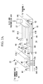
- Another type of recovery-type air cooling is a closed air cooling cycle, such as in a gas turbine GT′ shown in FIG. 15 , which bleeds and pressurizes the compressed air and supplies the pressurized air to both the stator blades 8 and the rotor blades 10 of the turbine 7 for cooling them.
- the branch passage 4 is divided into two lines, one for supplying the pressurized air to the stator blades 8 and the other for supplying the pressurized air to the rotor blades 10 .
- reference sign 5 A is a pressurizing device
- reference sign 6 A is a pressurized-air passage
- reference sign 9 A is a return passage
- reference sign 11 is a cooling device, all of which are provided in the line for supplying and recovering the pressurized air to and from the rotor blades 10 .
- Patent Literature 1 discloses a method for operating a gas turbine at partial load in which compressed air bled from near the outlet of a compressor is pressurized by operating a pressurizing device and is made to flow through a cooling passage in a combustor to perform cooling.
- PTL 2 discloses a method for operating a gas turbine at rated load in which compressed air bled from near the outlet of a compressor is pressurized by operating a pressurizing device and is made to flow through a turbine coolant passage and a cooling passage in a combustor to perform cooling.
- What is desired for a gas turbine that employs the recovery-type air cooling system (closed air cooling cycle) described above is a cooling structure that can effectively utilize compressed air supplied from a compressor to efficiently cool the wall of a combustor.
- the present invention employs the following solutions.
- a cooling structure according to the present invention for a recovery-type air-cooled gas turbine combustor is a cooling structure for a recovery-type air-cooled gas turbine combustor having a recovery-type air-cooling structure that bleeds, upstream of the combustor, and pressurizes compressed air supplied from a compressor, that uses the bled and pressurized air to cool a wall of the combustor, and that recovers and reuses the bled and pressurized air as combustion air for burning fuel in the combustor together with a main flow of the compressed air, and wall cooling in which cooling air is supplied to cooling air passages formed in the wall of the combustor to perform cooling involves a downstream wall region, closer to a turbine, that is cooled using the bled and pressurized air as the cooling air and an upstream wall region, closer to a burner, that is cooled using, as the cooling air, bled compressed air bled from a main flow of the compressed air through a housing.
- the cooling structure of the present invention for the recovery-type air-cooled gas turbine combustor can effectively utilize the bled and pressurized air and the bled compressed air to cool the wall of the combustor.
- wall cooling using the bled and pressurized air is performed in the region of the combustor closer to the turbine (downstream wall region), which is at a relatively high temperature
- wall cooling using the bled compressed air is performed in the region of the combustor closer to the burner (upstream wall region), which is at a relatively low temperature
- wall cooling is possible using a reduced amount of bled and pressurized air.
- bled and pressurized air introduced from bled-and-pressurized-air inlet holes provided closer to the turbine preferably flows out of bled-and-pressurized-air outlet holes provided closer to the burner in the downstream wall region into an inner space of the housing
- at least bled compressed air introduced from bled-compressed-air inlet holes provided closer to the turbine in the upstream wall region preferably flows out of bled-compressed-air outlet holes provided in the center of the upstream wall region, which allows the bled and pressurized air to be supplied from near an outlet of a tailpipe, which is exposed to a higher heat load, for wall cooling in the downstream wall region, thus allowing wall cooling using a further reduced amount of bled and pressurized air.
- the bled-and-pressurized-air outlet holes and/or the bled-compressed-air inlet holes that are adjacent to each other near a boundary between the upstream wall region and the downstream wall region are preferably arranged in a staggered pattern, which allows the opening positions of the bled-and-pressurized-air outlet holes and/or the bled-compressed-air inlet holes to be dispersed near the boundary between the upstream wall region and the downstream wall region so that the wall can be efficiently cooled.
- bled-and-pressurized-air cooling passages that direct the bled and pressurized air introduced from the bled-and-pressurized-air inlet holes to the bled-and-pressurized-air outlet holes and/or bled-compressed-air cooling passages that direct the bled compressed air introduced from the bled-compressed-air inlet holes to the bled-compressed-air outlet holes preferably include turn-back portions that couple together the cooling passages that are adjacent to each other in a circumferential direction of the combustor near the boundary, which allows the opening positions of the adjacent bled-and-pressurized-air outlet holes and bled-compressed-air inlet holes near the boundary to be spaced apart from each other to prevent or inhibit mixing of the bled and pressurized air and the bled compressed air so that the temperature of the compressed air that cools the upstream wall region does not rise.
- the turn-back portions are preferably routed so as to substantially uniformly cover a region near the boundary between the upstream wall region and the downstream wall region to perform wall cooling using the bled and pressurized air and/or the bled compressed air, which allows substantially uniform wall cooling if the turn-back portions are routed through a region separated from the positions of the bled-and-pressurized-air outlet holes and the bled-compressed-air inlet holes.
- a partition wall protruding from the wall of the combustor is preferably provided between the bled-and-pressurized-air outlet holes and the bled-compressed-air inlet holes, which allows the flow of the bled and pressurized air out of the bled-and-pressurized-air outlet holes to be reliably separated from the flow of the bled compressed air into the bled-compressed-air inlet holes without being mixed therewith.
- the ratio (P/d) of a pitch (P) of the bled-and-pressurized-air outlet holes and the bled-compressed-air inlet holes that are adjacent to each other near the boundary in a longitudinal direction of the combustor to the diameter (d) of the bled-and-pressurized-air outlet holes is preferably set to 2 or more (P/d ⁇ 2), which allows a sufficient distance to be provided between the adjacent bled-and-pressurized-air outlet holes and bled-compressed-air inlet holes so that the flow of the bled and pressurized air out of the bled-and-pressurized-air outlet holes and the flow of the bled compressed air into the bled-compressed-air inlet holes are not mixed with each other.
- the diameter (di) of the bled-compressed-air inlet holes is preferably set to a value larger than the diameter (d) of the bled-and-pressurized-air outlet holes (di>d), which allows the bled and pressurized air flowing out of the bled-and-pressurized-air outlet holes, which have a smaller diameter, to have a higher velocity, so that the high-temperature bled and pressurized air tends to flow out into the inner space of the housing without being mixed with the bled compressed air, which has a lower velocity.
- the bled compressed air flowing into the bled-compressed-air inlet holes tends not to be mixed with the high-temperature bled and pressurized air, thus preventing or inhibiting a temperature rise.
- a boundary between the upstream wall region and the downstream wall region is preferably located near an end of an acoustic liner closer to the turbine, which allows the amount of bled and pressurized air to be reduced for improved cycle performance.
- the cooling structure for the recovery-type air-cooled gas turbine combustor which employs recovery-type air cooling (closed air cooling cycle)
- the bled and pressurized air that has been used to cool the downstream wall region of the combustor and the bled compressed air that has been used to cool the upstream wall region of the combustor are both effectively reused as combustion air, thus providing a gas turbine having a cooling structure employing recovery-type air cooling that can efficiently cool the wall of the combustor using a reduced amount of bled and pressurized air, which needs to be pressurized.
- FIG. 1 is a sectional view illustrating a wall cooling system of a combustor as an embodiment of a cooling structure for a recovery-type air-cooled gas turbine combustor according to the present invention.
- FIG. 2A is an enlarged view illustrating a relevant part of the wall cooling system of the combustor illustrated in FIG. 1 and is a sectional perspective view illustrating the wall cooling system from the upstream side to the downstream side thereof.
- FIG. 2B is a schematic plan view of the wall cooling system in FIG. 2A as viewed from outside the combustor.
- FIG. 3A is an enlarged view illustrating the relevant part of the wall cooling system of the combustor illustrated in FIG. 1 and is a sectional view taken along line A-A in FIG. 3C .
- FIG. 3B is an enlarged view illustrating the relevant part of the wall cooling system of the combustor illustrated in FIG. 1 and is a sectional view taken along line B-B in FIG. 3C .
- FIG. 3C is an enlarged view illustrating the relevant part of the wall cooling system of the combustor illustrated in FIG. 1 and is a schematic plan view of the wall cooling system in FIGS. 3A and 3B as viewed from outside the combustor.
- FIG. 4 is a diagram illustrating an example of the configuration of a gas turbine that performs recovery-type air cooling on a wall of a combustor.
- FIG. 5 is a diagram illustrating an example of the structure of the combustor of the gas turbine and the surrounding thereof.
- FIG. 6A illustrates a first modification illustrating an example of the arrangement of cooling passages and cooling air inlets/outlets in the wall of the combustor, showing a pattern in which turn-back portions are provided for bled-compressed-air cooling passages and in which bled-compressed-air inlet holes are differently arranged.
- FIG. 6B illustrates a first modification illustrating an example of the arrangement of cooling passages and cooling air inlets/outlets in the wall of the combustor, showing a pattern in which the turn-back portions are provided for the bled-compressed-air cooling passages and in which the bled-compressed-air inlet holes are differently arranged.
- FIG. 6C illustrates a first modification illustrating an example of the arrangement of cooling passages and cooling air inlets/outlets in the wall of the combustor, showing a pattern in which the turn-back portions are provided for the bled-compressed-air cooling passages and in which the bled-compressed-air inlet holes are differently arranged.
- FIG. 7 illustrates a second modification illustrating an example of the arrangement of cooling passages and cooling air inlets/outlets in the wall of the combustor, showing a pattern in which the turn-back portions are provided for the bled-compressed-air cooling passages and in which bled-and-pressurized-air outlet holes are differently arranged.
- FIG. 8 illustrates a third modification illustrating an example of the arrangement of cooling passages and cooling air inlets/outlets in the wall of the combustor, showing a pattern in which the turn-back portions are provided for both the bled-and-pressurized-air cooling passage and the bled-compressed-air cooling passages.
- FIG. 9 illustrates a fourth modification illustrating an example of the arrangement of cooling passages and cooling air inlets/outlets in the wall of the combustor, showing a pattern in which the turn-back portions provided for the bled-compressed-air cooling passages are differently routed.
- FIG. 10 illustrates a fifth modification illustrating an example of the arrangement of cooling passages and cooling air inlets/outlets in the wall of the combustor, showing a pattern in which the turn-back portions are provided for the bled-and-pressurized-air cooling air.
- FIG. 11A is a diagram illustrating a sixth modification including a partition wall, showing a schematic plan view illustrating an example of the arrangement of cooling passages and cooling air inlets/outlets in the wall of the combustor.
- FIG. 11B is a sectional view taken along line C-C of FIG. 11A .
- FIG. 12 is a graph showing the relationship between the ratio (P/d) of the pitch (P) of adjacent bled-and-pressurized-air outlet holes and bled-compressed-air inlet holes to the diameter (d) of the bled-and-pressurized-air outlet holes and the mixed temperature of bled compressed air.
- FIG. 13 is a graph showing the relationship between the ratio of the diameter (di) of the bled-compressed-air inlet holes to the diameter (d) of the bled-and-pressurized-air outlet holes and the mixed temperature of the bled compressed air.
- FIG. 14 is a diagram of an air cooling system for cooling stator blades of a turbine using compressed air as an example of a recovery-type air cooling system applied to gas turbines in the related art.
- FIG. 15 is a diagram of an air cooling system for cooling stator blades and rotor blades of a turbine using compressed air as an example of a recovery-type air cooling system applied to gas turbines in the related art.
- FIG. 4 is a schematic configuration diagram illustrating a gas turbine according to this embodiment
- FIG. 5 is a sectional view illustrating an example of the surrounding structure of a combustor of the gas turbine.
- the illustrated gas turbine drives a generator, although it is not limited thereto.
- a gas turbine GT 1 is composed of a compressor 1 , a combustor 30 , and a turbine 7 to which a generator Ge is coupled.
- the compressor 1 compresses air taken in from the atmosphere.
- the main flow of the compressed air is supplied to the combustor 30 through a compressed-air supply passage 2 .
- the combustor 30 burns fuel with the compressed air compressed by the compressor 1 to produce a high-temperature, high-pressure combustion gas.
- the combustion gas is supplied to the turbine 7 .
- the turbine 7 has alternating rows of stator blades and rotor blades in a turbine housing thereof.
- the turbine 7 allows the combustion gas to flow between the stator blades and the rotor blades to rotate a rotor to which the rotor blades are affixed, thereby producing driving force for the generator Ge.
- the gas turbine GT 1 discussed above includes a pressurizing device 5 that bleeds a portion of the compressed air compressed by the compressor 1 and that pressurizes the portion to a pressure higher than that of the compressed air.
- the pressurizing device 5 is disposed in a branch passage 4 that branches off at some location from the compressed-air supply passage 2 and through which a portion of the compressed air is bled, and is driven by an electric motor M.
- the bled and pressurized air pressurized by the pressurizing device 5 is supplied through a pressurized-air passage 6 B to the combustor 30 , where it is used as cooling air for cooling the wall of the combustor 30 .
- the bled and pressurized air that has thus been used for cooling the wall of the combustor 30 returns through a return passage 9 B to the compressed-air supply passage 2 , merges with the main flow of the compressed air through the compressed-air supply passage 2 , and is reused as the combustion air for burning the fuel in the combustor 30 .
- the gas turbine GT 1 discussed above includes a recovery-type air-cooling structure that cools the wall of the combustor 30 using the bled and pressurized air, which is supplied from the compressor 1 , bled upstream of the combustor 30 , and pressurized and that recovers the bled and pressurized air and reuses it as the combustion air for burning the fuel in the combustor 30 together with the main flow of the compressed air.
- the illustrated recovery-type air-cooling structure uses the bled and pressurized air only to cool the wall of the combustor 30 , it may also be used for cooling of the stator blades 8 and the rotor blades 10 of the turbine 7 as in the related art discussed above.
- the combustor 30 has a substantially cylindrical shape; for example, as shown in FIG. 5 , a plurality of combustors 30 are accommodated and installed in a housing inner space 12 formed in a housing (casing) Ca of the gas turbine GT 1 and are arranged circumferentially around the rotor.
- Each combustor 30 includes an inner cylinder 31 , a tailpipe 32 , and an acoustic liner 33 , and a combustion burner 34 is disposed in the inner cylinder 31 .
- the combustion burner 34 includes a pilot burner 35 disposed in the center thereof and a plurality of main burners 36 arranged around the pilot burner 35 .
- the compressed air compressed by the compressor 1 is introduced into and fills the inner space 12 of the housing Ca in which the combustors 30 are installed.
- the compressed air introduced into the housing inner space 12 flows from the upstream portions (closer to the combustion burners 34 ) of the combustors 30 into the inner cylinders 31 , where the compressed air is mixed with the fuel supplied from the combustion burners 34 and is burned. This burning produces a high-temperature, high-pressure combustion gas that is supplied through the tailpipes 32 to the turbine 7 located downstream.
- each combustor 30 of the gas turbine GT 1 performs wall cooling by supplying cooling air to cooling air passages 41 formed in a wall 40 of the combustor 30 , and the combustor 30 includes a downstream wall region, closer to the turbine 7 , that is cooled using the bled and pressurized air as the cooling air and an upstream wall region, closer to the combustion burner 34 , that is cooled using, as the cooling air, the bled compressed air bled from the main flow of the compressed air through the inner space 12 of the housing Ca.
- the wall 40 forming the tailpipe 32 of the combustor 30 has a double-walled structure including an inner wall 40 a and an outer wall 40 b that are brazed together, and for example, grooves formed on the outer wall 40 b , which is thicker, and extending in the axial direction (longitudinal direction) of the combustor 30 form cooling air passages 41 after the inner wall 40 a is brazed thereto.
- the combustor 30 has a large number of cooling air passages 41 arranged adjacently in parallel in the circumferential direction thereof.
- reference sign 33 a is an acoustic hole passing through the wall 40 .
- the boundary between the upstream region, which is cooled with the bled compressed air, and the downstream region, which is cooled with the bled and pressurized air, lies closer to the turbine 7 than the acoustic liner 33 does and is near the end of the acoustic liner 33 closer to the turbine 7 .
- the cooling air passages 41 are divided into bled-compressed-air cooling passages (hereinafter referred to as “compressed cooling passages”) 41 A through which the bled compressed air flows and bled-and-pressurized-air cooling passages (hereinafter referred to as “pressurized cooling passages”) 41 B through which the bled and pressurized air flows.
- the bled and pressurized air introduced from near the trailing end of the tailpipe 32 flows into the pressurized cooling passages 41 B and exits from near the end of the acoustic liner 33 closer to the turbine 7 into the housing inner space 12 .
- the bled and pressurized air is directed through the pressurized-air passage 6 B into a manifold 37 disposed near the trailing end of the tailpipe 32 .
- bled-and-pressurized-air inlet holes (hereinafter referred to as “pressurized inlet holes”) 42 are provided from passage to passage as the inlets of the pressurized cooling passages 41 B through which the bled and pressurized air flows in the wall 40 .
- pressurized outlet holes 43 are provided closer to the turbine 7 than the acoustic liner 33 is and near the end of the acoustic liner 33 closer to the turbine 7 .
- the bled and pressurized air flowing from the manifold 37 into the pressurized inlet holes 42 flows through the pressurized cooling passages 41 B toward the acoustic liner 33 to cool the wall 40 , and the bled and pressurized air whose temperature has risen flows out of the pressurized outlet holes 43 into the housing inner space 12 .
- the high-temperature bled and pressurized air flowing out into the housing inner space 12 merges with the compressed air filling the housing inner space 12 and is reused as combustion air.
- the compressed air in the housing inner space 12 is bled from near the ends of the acoustic liner 33 closer to the turbine 7 and the burner 34 , and the bled compressed air flows through the compressed cooling passages 41 A into the interior of the acoustic liner 33 .
- the acoustic liner 33 has numerous acoustic holes 33 a passing through the wall 40 inside a liner body 33 b extending in the circumferential direction of the combustor 30 .
- the compressed cooling passages 41 A therefore, are provided at positions where the acoustic holes 33 a are not formed.
- the compressed cooling passages 41 A have bled-compressed-air inlet holes (hereinafter referred to as “compressed inlet holes”) 44 provided outside and near the ends of the liner body 33 b and bled-compressed-air outlet holes (hereinafter referred to as “compressed outlet holes”) 45 provided inside the liner body 33 b in the center of the upstream wall region.
- compressed inlet holes bled-compressed-air inlet holes
- compressed outlet holes bled-compressed-air outlet holes
- the compressed air filling the housing inner space 12 is bled from the compressed inlet holes 44 near the liner body 33 b and flows through the compressed cooling passages 41 A to cool the wall 40 in the region around the acoustic liner 33 , and the bled compressed air whose temperature has risen flows out of the compressed outlet holes 45 into the acoustic liner 33 and flows through the acoustic holes 33 a into a combustion chamber 38 of the combustor 30 , where it is used for combustion.
- wall cooling using the bled and pressurized air in the downstream wall region and wall cooling using the bled compressed air in the upstream wall region can be performed in the region of the tailpipe 32 of the combustor 30 closer to the turbine 7 (downstream wall region), which is at a relatively high temperature
- wall cooling using the bled compressed air can be performed in the region of the tailpipe 32 of the combustor 30 closer to the combustion burner 34 (upstream wall region), which is at a relatively low temperature.
- the upstream wall region which is cooled using the bled compressed air, is provided, the amount of bled and pressurized air can be reduced, which allows for a reduction in the size of the pressurizing device 5 and a reduction in the power consumed for driving.
- pressurized outlet holes 43 and compressed inlet holes 44 described above are adjacent to each other in the longitudinal direction (combustion gas flow direction) of the combustor 30 near the boundary between the upstream wall region and the downstream wall region.
- the pressurized outlet holes 43 and the compressed inlet holes 44 may be arranged respectively in lines in the circumferential direction of the combustor 30 , although a staggered arrangement is desirable.
- Such a staggered arrangement disperses the pressurized outlet holes 43 , from which the high-temperature bled and pressurized air flows out, so that efficient wall cooling can be performed near the boundary between the upstream wall region and the downstream wall region downstream of the acoustic liner 33 in the combustion gas flow direction, where the pressurized outlet holes 43 are provided.
- the pressurized outlet holes 43 from which the high-temperature air flows out after cooling
- the compressed inlet holes 44 into which the low-temperature air flows before cooling
- airflows having a temperature difference might be mixed.
- Such mixing might increase the temperature of the bled compressed air flowing into the compressed inlet holes 44 before cooling, thus decreasing the capacity for cooling the upstream wall region of the wall 40 in which the compressed cooling passages 41 A are formed to supply the bled compressed air for wall cooling.
- At least the pressurized cooling passages 41 B which supply the bled and pressurized air to the pressurized outlet holes 43 provided on the side of the acoustic liner 33 closer to the turbine 7 and near the boundary between the upstream wall region and the downstream wall region, and/or the compressed cooling passages 41 A, which direct the bled compressed air introduced from the compressed inlet holes 44 into the acoustic liner 33 , include turn-back portions 50 that couple together the cooling passages adjacent to each other in the circumferential direction of the combustor 30 on the side of the acoustic liner 33 closer to the turbine 7 and near the boundary between the upstream wall region and the downstream wall region.
- turn-back portions 50 allow the opening positions of the adjacent pressurized outlet holes 43 and compressed inlet holes 44 near the boundary to be spaced apart from each other to prevent or inhibit mixing of the bled and pressurized air and the bled compressed air so that the temperature of the bled compressed air that cools the upstream wall region does not rise. It is also desirable to route the turn-back portions 50 so as to substantially uniformly cover the region near the boundary between the upstream wall region and the downstream wall region to perform wall cooling using the bled and pressurized air or the bled compressed air.
- a first modification illustrated in FIGS. 6A to 6C includes substantially U-shaped turn-back portions 50 for the compressed cooling passages 41 A. Specifically, the ends of two adjacent compressed cooling passages 41 A closer to the turbine 7 are coupled together in a U-shape, and the compressed inlet holes 44 are provided at positions spaced apart from the pressurized outlet holes 43 so that little high-temperature bled and pressurized air is mixed.
- turn-back portions 50 are formed so as to flow through the region separated from the opening positions of the pressurized outlet holes 43 and the compressed inlet holes 44 to cover the empty wall region where no pressurized outlet holes 43 or compressed inlet holes 44 are provided, substantially uniform wall cooling is also possible near the boundary between the upstream wall region and the downstream wall region.
- a second modification illustrated in FIG. 7 differs from the example in FIG. 6A discussed above in the arrangement of the pressurized outlet holes 43 and the compressed inlet holes 44 .
- three pressurized outlet holes 43 corresponding to each turn-back portion 50 are arranged linearly in the circumferential direction of the combustor 30 , and at the positions between two adjacent turn-back portions 50 , the pressurized outlet holes 43 are provided by extending the pressurized cooling passages 41 B toward the acoustic liner 33 .
- the compressed inlet holes 44 are provided at three positions, rather than at one position as in FIG. 6A .
- a third modification illustrated in FIG. 8 differs from the modification in FIG. 7 discussed above in the structure of the pressurized cooling passages 41 B.
- the substantially U-shaped turn-back portions 50 are also provided for the pressurized cooling passages 41 B, and the number and arrangement of the pressurized outlet holes 43 differ.
- a fourth modification illustrated in FIG. 9 has the substantially U-shaped turn-back portions 50 in FIG. 7 discussed above replaced by substantially M-shaped turn-back portions 51 .
- the substantially U-shaped turn-back portions 50 discussed above can be provided for the compressed cooling passages 41 A or the pressurized cooling passages 41 B, or both.
- the turn-back portions 50 are not necessarily substantially U-shaped, but may have any other shape, including the substantially M-shaped turn-back portions 51 and substantially S-shaped turn-back portions.
- the turn-back portions 50 may be selected from the modifications illustrated in FIGS. 6 to 10 and combinations thereof so that the distances between the pressurized outlet holes 43 and the compressed inlet holes 44 are optimized and that the turn-back portions 50 pass through and cover the empty wall region to allow substantially uniform wall cooling near the boundary between the upstream wall region and the downstream wall region.
- FIGS. 11A and 11B A sixth modification including a partition wall will then be described based on FIGS. 11A and 11B .
- the portions similar to those of the embodiment and modifications thereof described above are indicated by the same reference signs, and a detailed description thereof is omitted.
- a partition wall 60 protruding from the wall 40 of the combustor 30 is provided between the pressurized outlet holes 43 and the compressed inlet holes 44 near the boundary between the upstream wall region and the downstream wall region.
- This partition wall 60 protrudes from the wall 40 into the housing inner space 12 to reliably prevent the bled and pressurized air flowing out of the pressurized outlet holes 43 , which is at a higher temperature, from being mixed with the bled compressed air flowing into the compressed inlet holes 44 , which is at a lower temperature.
- the partition wall 60 is a wall member that separates the flow of the bled and pressurized air out of the pressurized outlet holes 43 from the flow of the bled compressed air into the compressed inlet holes 44 , thus allowing both airflows to be reliably separated without being mixed together.
- the illustrated structure includes a guide portion 61 formed by bending the end of the partition wall 60 toward the trailing end of the tailpipe 32 (toward the turbine 7 ).
- This guide portion 61 forms a guide surface substantially parallel to the wall 40 to guide the flow of the bled and pressurized air out of the pressurized outlet holes 43 toward the downstream side facing away from the compressed inlet holes 44 (toward the trailing end of the tailpipe 32 ), thus more reliably preventing mixing of the bled and pressurized air and the bled compressed air.
- This partition wall 60 is applicable to the embodiment and modifications thereof described above, any of which produces a synergetic effect to allow for more efficient wall cooling of the combustor 30 .
- FIG. 12 shows the relationship between the ratio (P/d) of the pitch (P) of the adjacent pressurized outlet holes 43 and compressed inlet holes 44 to the diameter (d) of the pressurized outlet holes 43 and the mixed temperature of the bled compressed air, which represents the mixed state of the bled and pressurized air and the bled compressed air.
- This figure shows that the mixed temperature varies little as (P/d) is increased to 2 or more.
- the diameter (di) of the compressed inlet holes 44 provided near the boundary between the upstream wall region and the downstream wall region be set to a value larger than the diameter (d) of the pressurized outlet holes 43 (di>d).
- the compressed air supplied from the compressor 1 can be effectively utilized in the gas turbine GT 1 , which employs recovery-type air cooling (closed air cooling cycle), to perform wall cooling using the bled and pressurized air in the region of the combustor 30 closer to the turbine 7 , which is at a relatively high temperature, and to perform wall cooling using the bled compressed air closer to the combustion burner 34 .
- recovery-type air cooling closed air cooling cycle
- the bled and pressurized air that has been used to cool the downstream wall region of the combustor 30 and the bled compressed air that has been used to cool the upstream wall region of the combustor 30 are both effectively reused as combustion air, thus providing a gas turbine having a cooling structure employing recovery-type air cooling that can efficiently cool the wall of the combustor 30 .
- the amount of bled and pressurized air (amount of closed-cycle cooling air) can be reduced, which improves the cycle performance of the gas turbine. That is, both the bled and pressurized air and the bled compressed air can be used for cooling of the acoustic liner 33 because they can provide a sufficient pressure difference, and therefore the use of the bled compressed air, which does not need to be pressurized, for cooling is advantageous for improving the cycle performance because, for example, no power is needed for pressurization.
Landscapes
- Engineering & Computer Science (AREA)
- Chemical & Material Sciences (AREA)
- Combustion & Propulsion (AREA)
- Mechanical Engineering (AREA)
- General Engineering & Computer Science (AREA)
- Turbine Rotor Nozzle Sealing (AREA)
- Gas Burners (AREA)
Abstract
Description
- 1 compressor
- 3, 30 combustor
- 5 pressurizing device
- 7 turbine
- 12 housing inner space
- 31 inner cylinder
- 32 tailpipe
- 33 acoustic liner
- 33 a acoustic hole
- 33 b liner body
- 34 combustion burner
- 37 manifold
- 38 combustion chamber
- 40 wall
- 41 cooling air passage
- 41A bled-compressed-air cooling passage (compressed cooling passage)
- 41B bled-and-pressurized-air cooling passage (pressurized cooling passage)
- 42 bled-and-pressurized-air inlet hole (pressurized inlet hole)
- 43 bled-and-pressurized-air outlet hole (pressurized outlet hole)
- 44 bled-compressed-air inlet hole (compressed inlet hole)
- 45 bled-compressed-air outlet hole (compressed outlet hole)
- 46 cooling branch passage
- 50, 51 turn-back portion
- 60 partition wall
- 61 guide portion
- GT1 gas turbine
Claims (11)
Applications Claiming Priority (3)
| Application Number | Priority Date | Filing Date | Title |
|---|---|---|---|
| JP2010-222494 | 2010-09-30 | ||
| JP2010222494A JP5653705B2 (en) | 2010-09-30 | 2010-09-30 | Recovery air cooling gas turbine combustor cooling structure |
| PCT/JP2011/068234 WO2012043073A1 (en) | 2010-09-30 | 2011-08-10 | Air recovery-type cooling structure for air-cooled gas turbine combustor |
Publications (2)
| Publication Number | Publication Date |
|---|---|
| US20130098063A1 US20130098063A1 (en) | 2013-04-25 |
| US9512781B2 true US9512781B2 (en) | 2016-12-06 |
Family
ID=45892548
Family Applications (1)
| Application Number | Title | Priority Date | Filing Date |
|---|---|---|---|
| US13/806,523 Active 2033-10-04 US9512781B2 (en) | 2010-09-30 | 2011-08-10 | Cooling structure for recovery-type air-cooled gas turbine combustor |
Country Status (6)
| Country | Link |
|---|---|
| US (1) | US9512781B2 (en) |
| EP (1) | EP2623744B1 (en) |
| JP (1) | JP5653705B2 (en) |
| KR (1) | KR101477372B1 (en) |
| CN (1) | CN102971510B (en) |
| WO (1) | WO2012043073A1 (en) |
Cited By (19)
| Publication number | Priority date | Publication date | Assignee | Title |
|---|---|---|---|---|
| US10520194B2 (en) | 2016-03-25 | 2019-12-31 | General Electric Company | Radially stacked fuel injection module for a segmented annular combustion system |
| US10563869B2 (en) | 2016-03-25 | 2020-02-18 | General Electric Company | Operation and turndown of a segmented annular combustion system |
| US10584638B2 (en) | 2016-03-25 | 2020-03-10 | General Electric Company | Turbine nozzle cooling with panel fuel injector |
| US10584876B2 (en) | 2016-03-25 | 2020-03-10 | General Electric Company | Micro-channel cooling of integrated combustor nozzle of a segmented annular combustion system |
| US10584880B2 (en) | 2016-03-25 | 2020-03-10 | General Electric Company | Mounting of integrated combustor nozzles in a segmented annular combustion system |
| US10605459B2 (en) | 2016-03-25 | 2020-03-31 | General Electric Company | Integrated combustor nozzle for a segmented annular combustion system |
| US10641491B2 (en) | 2016-03-25 | 2020-05-05 | General Electric Company | Cooling of integrated combustor nozzle of segmented annular combustion system |
| US10690350B2 (en) | 2016-11-28 | 2020-06-23 | General Electric Company | Combustor with axially staged fuel injection |
| US10782025B2 (en) | 2015-09-15 | 2020-09-22 | Mitsubishi Hitachi Power Systems, Ltd. | Combustor pipe, combustor, and gas turbine |
| US10830442B2 (en) | 2016-03-25 | 2020-11-10 | General Electric Company | Segmented annular combustion system with dual fuel capability |
| US11156362B2 (en) | 2016-11-28 | 2021-10-26 | General Electric Company | Combustor with axially staged fuel injection |
| US11255545B1 (en) | 2020-10-26 | 2022-02-22 | General Electric Company | Integrated combustion nozzle having a unified head end |
| US11371702B2 (en) | 2020-08-31 | 2022-06-28 | General Electric Company | Impingement panel for a turbomachine |
| US11428413B2 (en) | 2016-03-25 | 2022-08-30 | General Electric Company | Fuel injection module for segmented annular combustion system |
| US11460191B2 (en) | 2020-08-31 | 2022-10-04 | General Electric Company | Cooling insert for a turbomachine |
| US11614233B2 (en) | 2020-08-31 | 2023-03-28 | General Electric Company | Impingement panel support structure and method of manufacture |
| US11767766B1 (en) | 2022-07-29 | 2023-09-26 | General Electric Company | Turbomachine airfoil having impingement cooling passages |
| US11994293B2 (en) | 2020-08-31 | 2024-05-28 | General Electric Company | Impingement cooling apparatus support structure and method of manufacture |
| US11994292B2 (en) | 2020-08-31 | 2024-05-28 | General Electric Company | Impingement cooling apparatus for turbomachine |
Families Citing this family (37)
| Publication number | Priority date | Publication date | Assignee | Title |
|---|---|---|---|---|
| DE102010051638A1 (en) * | 2010-11-17 | 2012-05-24 | Rolls-Royce Deutschland Ltd & Co Kg | Gas turbine combustor with a cooling air supply device |
| US9255484B2 (en) * | 2011-03-16 | 2016-02-09 | General Electric Company | Aft frame and method for cooling aft frame |
| US9175604B2 (en) * | 2011-09-08 | 2015-11-03 | Siemens Energy, Inc. | Gas turbine engine with high and intermediate temperature compressed air zones |
| JP5787857B2 (en) | 2012-09-27 | 2015-09-30 | 三菱日立パワーシステムズ株式会社 | Control method for gas turbine cooling system, control device for executing the method, and gas turbine equipment equipped with the control device |
| JP6041299B2 (en) * | 2012-11-15 | 2016-12-07 | 三菱日立パワーシステムズ株式会社 | Gas turbine combustor and gas turbine equipped with the combustor |
| US8834154B2 (en) * | 2012-11-28 | 2014-09-16 | Mitsubishi Heavy Industries, Ltd. | Transition piece of combustor, and gas turbine having the same |
| EP2762784B1 (en) * | 2012-11-30 | 2016-02-03 | Alstom Technology Ltd | Damping device for a gas turbine combustor |
| JP6004976B2 (en) * | 2013-03-21 | 2016-10-12 | 三菱重工業株式会社 | Combustor and gas turbine |
| US9366139B2 (en) * | 2013-04-09 | 2016-06-14 | Mitsubishi Heavy Industries, Ltd. | Repair method of plate member, plate member, combustor, ring segment, and gas turbine |
| DE112014006619B4 (en) | 2014-04-25 | 2023-11-16 | Mitsubishi Heavy Industries, Ltd. | Gas turbine combustion chamber and gas turbine provided with the same |
| JP6245757B2 (en) | 2014-05-22 | 2017-12-13 | 三菱日立パワーシステムズ株式会社 | COOLING DEVICE, GAS TURBINE EQUIPMENT HAVING THE SAME, AND COOLING DEVICE OPERATION METHOD |
| JP6331081B2 (en) * | 2014-05-22 | 2018-05-30 | 三菱日立パワーシステムズ株式会社 | Gas turbine equipment and cooling device operating method |
| WO2015186523A1 (en) * | 2014-06-04 | 2015-12-10 | 三菱日立パワーシステムズ株式会社 | Gas turbine |
| JP6175193B2 (en) * | 2014-07-25 | 2017-08-02 | 三菱日立パワーシステムズ株式会社 | Combustor cylinder, combustor and gas turbine |
| US9470421B2 (en) * | 2014-08-19 | 2016-10-18 | General Electric Company | Combustor cap assembly |
| US9964308B2 (en) * | 2014-08-19 | 2018-05-08 | General Electric Company | Combustor cap assembly |
| JP6623485B2 (en) * | 2014-09-25 | 2019-12-25 | 三菱日立パワーシステムズ株式会社 | Combustor and gas turbine including the same |
| JP6223954B2 (en) * | 2014-12-02 | 2017-11-01 | 三菱日立パワーシステムズ株式会社 | Combustor and gas turbine |
| CN104458283B (en) * | 2014-12-26 | 2017-05-03 | 长城汽车股份有限公司 | Airflow type cooling device and vehicle road simulating testing system |
| JP6476516B2 (en) * | 2015-01-30 | 2019-03-06 | 三菱日立パワーシステムズ株式会社 | Transition piece, combustor including the same, and gas turbine including the combustor |
| US10627110B2 (en) | 2015-02-24 | 2020-04-21 | Mitsubishi Hitachi Power Systems, Ltd. | Combustor cooling panel, transition piece and combustor including the same, and gas turbine including combustor |
| FR3037107B1 (en) * | 2015-06-03 | 2019-11-15 | Safran Aircraft Engines | ANNULAR ROOM OF COMBUSTION CHAMBER WITH OPTIMIZED COOLING |
| CN105423341B (en) * | 2015-12-30 | 2017-12-15 | 哈尔滨广瀚燃气轮机有限公司 | There is the premixed low emission gas turbine combustion chamber of flame on duty |
| JP6815735B2 (en) | 2016-03-03 | 2021-01-20 | 三菱パワー株式会社 | Audio equipment, gas turbine |
| JP6026028B1 (en) * | 2016-03-10 | 2016-11-16 | 三菱日立パワーシステムズ株式会社 | Combustor panel, combustor, combustion apparatus, gas turbine, and method for cooling combustor panel |
| GB2554384A (en) * | 2016-09-23 | 2018-04-04 | Hieta Tech Limited | Combustion chamber and heat exchanger |
| CN110446829B (en) * | 2017-03-30 | 2021-07-06 | 西门子股份公司 | System with conduit arrangement for dual utilization of cooling fluid in combustor section of gas turbine engine |
| JP6822894B2 (en) * | 2017-04-28 | 2021-01-27 | 三菱パワー株式会社 | Fuel injector and gas turbine |
| JP7193962B2 (en) * | 2018-09-26 | 2022-12-21 | 三菱重工業株式会社 | Combustor and gas turbine equipped with the same |
| JP6651665B1 (en) * | 2019-03-28 | 2020-02-19 | 三菱日立パワーシステムズ株式会社 | Turbine casing, gas turbine, and method for preventing deformation of turbine casing |
| US11156164B2 (en) | 2019-05-21 | 2021-10-26 | General Electric Company | System and method for high frequency accoustic dampers with caps |
| DE112020002536T5 (en) | 2019-05-24 | 2022-02-24 | Mitsubishi Power, Ltd. | TRANSITION PIECE, COMBUSTOR, GAS TURBINE AND GAS TURBINE EQUIPMENT |
| EP3954870B1 (en) * | 2020-08-14 | 2024-02-07 | Ansaldo Energia Switzerland AG | Transition duct for a gas turbine plant and gas turbine plant comprising said transition duct |
| KR102468746B1 (en) * | 2020-11-18 | 2022-11-18 | 한국항공우주연구원 | Combustor inclduing heat exchanging structure and rocket including the same |
| FR3119868B1 (en) * | 2021-02-15 | 2023-01-13 | Ifp Energies Now | Combustion system with a tubular combustion chamber and an annular heat exchanger |
| JP7326399B2 (en) * | 2021-09-30 | 2023-08-15 | 三菱重工業株式会社 | Transition pieces, combustors and gas turbine engines |
| JP7539532B2 (en) | 2022-08-24 | 2024-08-23 | 三菱重工業株式会社 | Combustor tube, combustor, and gas turbine |
Citations (15)
| Publication number | Priority date | Publication date | Assignee | Title |
|---|---|---|---|---|
| JPS5956618A (en) | 1982-09-27 | 1984-04-02 | Toshiba Corp | Transition piece for gas turbine |
| JPS59110336U (en) | 1983-01-17 | 1984-07-25 | 株式会社東芝 | steam injection device |
| US4719748A (en) * | 1985-05-14 | 1988-01-19 | General Electric Company | Impingement cooled transition duct |
| JP2001107748A (en) | 1999-10-07 | 2001-04-17 | Toshiba Corp | Gas turbine plant |
| US6282905B1 (en) * | 1998-11-12 | 2001-09-04 | Mitsubishi Heavy Industries, Ltd. | Gas turbine combustor cooling structure |
| JP2003214185A (en) | 2002-01-22 | 2003-07-30 | Mitsubishi Heavy Ind Ltd | Gas turbine combustor cooling structure and gas turbine |
| JP2004044538A (en) | 2002-07-15 | 2004-02-12 | Mitsubishi Heavy Ind Ltd | Burner cooling structure |
| JP2006220350A (en) | 2005-02-10 | 2006-08-24 | Hitachi Ltd | Gas turbine equipment and operation method thereof |
| US7310938B2 (en) * | 2004-12-16 | 2007-12-25 | Siemens Power Generation, Inc. | Cooled gas turbine transition duct |
| JP2008274774A (en) | 2007-04-25 | 2008-11-13 | Mitsubishi Heavy Ind Ltd | Gas turbine combustor and gas turbine |
| JP2009079483A (en) | 2007-09-25 | 2009-04-16 | Mitsubishi Heavy Ind Ltd | Gas turbine combustor |
| WO2010041552A1 (en) * | 2008-10-08 | 2010-04-15 | 三菱重工業株式会社 | Gas turbine and operating method therefor |
| JP2010090817A (en) | 2008-10-08 | 2010-04-22 | Mitsubishi Heavy Ind Ltd | Gas turbine and its operating method at partial load |
| JP2010090818A (en) | 2008-10-08 | 2010-04-22 | Mitsubishi Heavy Ind Ltd | Gas turbine and its rated operating method |
| US8720204B2 (en) * | 2011-02-09 | 2014-05-13 | Siemens Energy, Inc. | Resonator system with enhanced combustor liner cooling |
Family Cites Families (2)
| Publication number | Priority date | Publication date | Assignee | Title |
|---|---|---|---|---|
| JP2008082247A (en) * | 2006-09-27 | 2008-04-10 | Mitsubishi Heavy Ind Ltd | Gas turbine |
| JP4823186B2 (en) * | 2007-09-25 | 2011-11-24 | 三菱重工業株式会社 | Gas turbine combustor |
-
2010
- 2010-09-30 JP JP2010222494A patent/JP5653705B2/en active Active
-
2011
- 2011-08-10 EP EP11828634.3A patent/EP2623744B1/en active Active
- 2011-08-10 KR KR1020127033636A patent/KR101477372B1/en active Active
- 2011-08-10 US US13/806,523 patent/US9512781B2/en active Active
- 2011-08-10 CN CN201180031511.4A patent/CN102971510B/en active Active
- 2011-08-10 WO PCT/JP2011/068234 patent/WO2012043073A1/en not_active Ceased
Patent Citations (15)
| Publication number | Priority date | Publication date | Assignee | Title |
|---|---|---|---|---|
| JPS5956618A (en) | 1982-09-27 | 1984-04-02 | Toshiba Corp | Transition piece for gas turbine |
| JPS59110336U (en) | 1983-01-17 | 1984-07-25 | 株式会社東芝 | steam injection device |
| US4719748A (en) * | 1985-05-14 | 1988-01-19 | General Electric Company | Impingement cooled transition duct |
| US6282905B1 (en) * | 1998-11-12 | 2001-09-04 | Mitsubishi Heavy Industries, Ltd. | Gas turbine combustor cooling structure |
| JP2001107748A (en) | 1999-10-07 | 2001-04-17 | Toshiba Corp | Gas turbine plant |
| JP2003214185A (en) | 2002-01-22 | 2003-07-30 | Mitsubishi Heavy Ind Ltd | Gas turbine combustor cooling structure and gas turbine |
| JP2004044538A (en) | 2002-07-15 | 2004-02-12 | Mitsubishi Heavy Ind Ltd | Burner cooling structure |
| US7310938B2 (en) * | 2004-12-16 | 2007-12-25 | Siemens Power Generation, Inc. | Cooled gas turbine transition duct |
| JP2006220350A (en) | 2005-02-10 | 2006-08-24 | Hitachi Ltd | Gas turbine equipment and operation method thereof |
| JP2008274774A (en) | 2007-04-25 | 2008-11-13 | Mitsubishi Heavy Ind Ltd | Gas turbine combustor and gas turbine |
| JP2009079483A (en) | 2007-09-25 | 2009-04-16 | Mitsubishi Heavy Ind Ltd | Gas turbine combustor |
| WO2010041552A1 (en) * | 2008-10-08 | 2010-04-15 | 三菱重工業株式会社 | Gas turbine and operating method therefor |
| JP2010090817A (en) | 2008-10-08 | 2010-04-22 | Mitsubishi Heavy Ind Ltd | Gas turbine and its operating method at partial load |
| JP2010090818A (en) | 2008-10-08 | 2010-04-22 | Mitsubishi Heavy Ind Ltd | Gas turbine and its rated operating method |
| US8720204B2 (en) * | 2011-02-09 | 2014-05-13 | Siemens Energy, Inc. | Resonator system with enhanced combustor liner cooling |
Non-Patent Citations (3)
| Title |
|---|
| Japanese Office Action issued Oct. 21, 2014 is Japanese Patent Application No. 2010-222494. |
| Korean Notice of Allowance issued Nov. 20, 2014 in Korean Patent Application No. 10-2012-7033636. |
| Notice of Allowance issued Mar. 5, 2015 in corresponding Chinese patent application No. 201180031511.4. |
Cited By (25)
| Publication number | Priority date | Publication date | Assignee | Title |
|---|---|---|---|---|
| US10782025B2 (en) | 2015-09-15 | 2020-09-22 | Mitsubishi Hitachi Power Systems, Ltd. | Combustor pipe, combustor, and gas turbine |
| US10724441B2 (en) | 2016-03-25 | 2020-07-28 | General Electric Company | Segmented annular combustion system |
| US10641175B2 (en) | 2016-03-25 | 2020-05-05 | General Electric Company | Panel fuel injector |
| US10584876B2 (en) | 2016-03-25 | 2020-03-10 | General Electric Company | Micro-channel cooling of integrated combustor nozzle of a segmented annular combustion system |
| US10584880B2 (en) | 2016-03-25 | 2020-03-10 | General Electric Company | Mounting of integrated combustor nozzles in a segmented annular combustion system |
| US10605459B2 (en) | 2016-03-25 | 2020-03-31 | General Electric Company | Integrated combustor nozzle for a segmented annular combustion system |
| US10641491B2 (en) | 2016-03-25 | 2020-05-05 | General Electric Company | Cooling of integrated combustor nozzle of segmented annular combustion system |
| US10520194B2 (en) | 2016-03-25 | 2019-12-31 | General Electric Company | Radially stacked fuel injection module for a segmented annular combustion system |
| US10641176B2 (en) | 2016-03-25 | 2020-05-05 | General Electric Company | Combustion system with panel fuel injector |
| US10655541B2 (en) | 2016-03-25 | 2020-05-19 | General Electric Company | Segmented annular combustion system |
| US11428413B2 (en) | 2016-03-25 | 2022-08-30 | General Electric Company | Fuel injection module for segmented annular combustion system |
| US10584638B2 (en) | 2016-03-25 | 2020-03-10 | General Electric Company | Turbine nozzle cooling with panel fuel injector |
| US10690056B2 (en) | 2016-03-25 | 2020-06-23 | General Electric Company | Segmented annular combustion system with axial fuel staging |
| US10563869B2 (en) | 2016-03-25 | 2020-02-18 | General Electric Company | Operation and turndown of a segmented annular combustion system |
| US10830442B2 (en) | 2016-03-25 | 2020-11-10 | General Electric Company | Segmented annular combustion system with dual fuel capability |
| US11002190B2 (en) | 2016-03-25 | 2021-05-11 | General Electric Company | Segmented annular combustion system |
| US11156362B2 (en) | 2016-11-28 | 2021-10-26 | General Electric Company | Combustor with axially staged fuel injection |
| US10690350B2 (en) | 2016-11-28 | 2020-06-23 | General Electric Company | Combustor with axially staged fuel injection |
| US11371702B2 (en) | 2020-08-31 | 2022-06-28 | General Electric Company | Impingement panel for a turbomachine |
| US11460191B2 (en) | 2020-08-31 | 2022-10-04 | General Electric Company | Cooling insert for a turbomachine |
| US11614233B2 (en) | 2020-08-31 | 2023-03-28 | General Electric Company | Impingement panel support structure and method of manufacture |
| US11994293B2 (en) | 2020-08-31 | 2024-05-28 | General Electric Company | Impingement cooling apparatus support structure and method of manufacture |
| US11994292B2 (en) | 2020-08-31 | 2024-05-28 | General Electric Company | Impingement cooling apparatus for turbomachine |
| US11255545B1 (en) | 2020-10-26 | 2022-02-22 | General Electric Company | Integrated combustion nozzle having a unified head end |
| US11767766B1 (en) | 2022-07-29 | 2023-09-26 | General Electric Company | Turbomachine airfoil having impingement cooling passages |
Also Published As
| Publication number | Publication date |
|---|---|
| EP2623744A4 (en) | 2018-01-10 |
| JP2012077660A (en) | 2012-04-19 |
| EP2623744A1 (en) | 2013-08-07 |
| JP5653705B2 (en) | 2015-01-14 |
| WO2012043073A1 (en) | 2012-04-05 |
| CN102971510B (en) | 2015-06-17 |
| EP2623744B1 (en) | 2019-05-15 |
| KR20130025413A (en) | 2013-03-11 |
| CN102971510A (en) | 2013-03-13 |
| US20130098063A1 (en) | 2013-04-25 |
| KR101477372B1 (en) | 2014-12-29 |
Similar Documents
| Publication | Publication Date | Title |
|---|---|---|
| US9512781B2 (en) | Cooling structure for recovery-type air-cooled gas turbine combustor | |
| US9109454B2 (en) | Turbine bucket with pressure side cooling | |
| EP2612995B1 (en) | Turbine nozzle compartmentalized cooling system | |
| CN103052765B (en) | Gas turbine bucket and combustion gas turbine | |
| EP3171086A1 (en) | Combustor wall channel cooling system | |
| US9382810B2 (en) | Closed loop cooling system for a gas turbine | |
| US6672074B2 (en) | Gas turbine | |
| EP2921779A1 (en) | Combustion chamber with cooling sleeve | |
| EP2634370A1 (en) | Turbine bucket with a core cavity having a contoured turn | |
| EP2647799A2 (en) | Combustor with non-circular head end | |
| US9011078B2 (en) | Turbine vane seal carrier with slots for cooling and assembly | |
| EP3067622A1 (en) | Combustion chamber with double wall | |
| JP5998045B2 (en) | Turbine nozzle cooling assembly | |
| US10352244B2 (en) | Combustor cooling structure | |
| US9562439B2 (en) | Turbine nozzle and method for cooling a turbine nozzle of a gas turbine engine | |
| EP2647800B1 (en) | Transition nozzle combustion system | |
| US9528392B2 (en) | System for supporting a turbine nozzle | |
| EP2574730A2 (en) | Turbine Shroud Impingement System With Bellows | |
| EP3159497B1 (en) | System and method for wheel space temperature management | |
| JP6408871B2 (en) | Combustion casing manifold for high pressure air delivery to the fuel nozzle pilot system | |
| JP2014092156A (en) | Inducer guide vanes |
Legal Events
| Date | Code | Title | Description |
|---|---|---|---|
| AS | Assignment |
Owner name: MITSUBISHI HEAVY INDUSTRIES, LTD., JAPAN Free format text: ASSIGNMENT OF ASSIGNORS INTEREST;ASSIGNORS:MIZUKAMI, SATOSHI;ISHIGURO, TATSUO;MASADA, JUNICHIRO;AND OTHERS;REEL/FRAME:029559/0552 Effective date: 20121128 Owner name: TOHOKU ELECTRIC POWER CO., INC., JAPAN Free format text: ASSIGNMENT OF ASSIGNORS INTEREST;ASSIGNORS:MIZUKAMI, SATOSHI;ISHIGURO, TATSUO;MASADA, JUNICHIRO;AND OTHERS;REEL/FRAME:029559/0552 Effective date: 20121128 |
|
| AS | Assignment |
Owner name: MITSUBISHI HITACHI POWER SYSTEMS, LTD., JAPAN Free format text: ASSIGNMENT OF ASSIGNORS INTEREST;ASSIGNOR:MITSUBISHI HEAVY INDUSTRIES, LTD.;REEL/FRAME:034906/0438 Effective date: 20150202 |
|
| STCF | Information on status: patent grant |
Free format text: PATENTED CASE |
|
| MAFP | Maintenance fee payment |
Free format text: PAYMENT OF MAINTENANCE FEE, 4TH YEAR, LARGE ENTITY (ORIGINAL EVENT CODE: M1551); ENTITY STATUS OF PATENT OWNER: LARGE ENTITY Year of fee payment: 4 |
|
| AS | Assignment |
Owner name: MITSUBISHI POWER, LTD., JAPAN Free format text: CHANGE OF NAME;ASSIGNOR:MITSUBISHI HITACHI POWER SYSTEMS, LTD.;REEL/FRAME:054975/0438 Effective date: 20200901 |
|
| AS | Assignment |
Owner name: MITSUBISHI POWER, LTD., JAPAN Free format text: CORRECTIVE ASSIGNMENT TO CORRECT THE REMOVING PATENT APPLICATION NUMBER 11921683 PREVIOUSLY RECORDED AT REEL: 054975 FRAME: 0438. ASSIGNOR(S) HEREBY CONFIRMS THE ASSIGNMENT;ASSIGNOR:MITSUBISHI HITACHI POWER SYSTEMS, LTD.;REEL/FRAME:063787/0867 Effective date: 20200901 |
|
| MAFP | Maintenance fee payment |
Free format text: PAYMENT OF MAINTENANCE FEE, 8TH YEAR, LARGE ENTITY (ORIGINAL EVENT CODE: M1552); ENTITY STATUS OF PATENT OWNER: LARGE ENTITY Year of fee payment: 8 |