US9511752B2 - Method for operating a brake system, and brake system - Google Patents
Method for operating a brake system, and brake system Download PDFInfo
- Publication number
- US9511752B2 US9511752B2 US14/124,490 US201214124490A US9511752B2 US 9511752 B2 US9511752 B2 US 9511752B2 US 201214124490 A US201214124490 A US 201214124490A US 9511752 B2 US9511752 B2 US 9511752B2
- Authority
- US
- United States
- Prior art keywords
- pressure
- actuator
- value
- pressure chamber
- hydraulic pressure
- Prior art date
- Legal status (The legal status is an assumption and is not a legal conclusion. Google has not performed a legal analysis and makes no representation as to the accuracy of the status listed.)
- Active
Links
Images


Classifications
-
- B—PERFORMING OPERATIONS; TRANSPORTING
- B60—VEHICLES IN GENERAL
- B60T—VEHICLE BRAKE CONTROL SYSTEMS OR PARTS THEREOF; BRAKE CONTROL SYSTEMS OR PARTS THEREOF, IN GENERAL; ARRANGEMENT OF BRAKING ELEMENTS ON VEHICLES IN GENERAL; PORTABLE DEVICES FOR PREVENTING UNWANTED MOVEMENT OF VEHICLES; VEHICLE MODIFICATIONS TO FACILITATE COOLING OF BRAKES
- B60T8/00—Arrangements for adjusting wheel-braking force to meet varying vehicular or ground-surface conditions, e.g. limiting or varying distribution of braking force
- B60T8/17—Using electrical or electronic regulation means to control braking
-
- B—PERFORMING OPERATIONS; TRANSPORTING
- B60—VEHICLES IN GENERAL
- B60T—VEHICLE BRAKE CONTROL SYSTEMS OR PARTS THEREOF; BRAKE CONTROL SYSTEMS OR PARTS THEREOF, IN GENERAL; ARRANGEMENT OF BRAKING ELEMENTS ON VEHICLES IN GENERAL; PORTABLE DEVICES FOR PREVENTING UNWANTED MOVEMENT OF VEHICLES; VEHICLE MODIFICATIONS TO FACILITATE COOLING OF BRAKES
- B60T13/00—Transmitting braking action from initiating means to ultimate brake actuator with power assistance or drive; Brake systems incorporating such transmitting means, e.g. air-pressure brake systems
- B60T13/10—Transmitting braking action from initiating means to ultimate brake actuator with power assistance or drive; Brake systems incorporating such transmitting means, e.g. air-pressure brake systems with fluid assistance, drive, or release
- B60T13/58—Combined or convertible systems
-
- B—PERFORMING OPERATIONS; TRANSPORTING
- B60—VEHICLES IN GENERAL
- B60T—VEHICLE BRAKE CONTROL SYSTEMS OR PARTS THEREOF; BRAKE CONTROL SYSTEMS OR PARTS THEREOF, IN GENERAL; ARRANGEMENT OF BRAKING ELEMENTS ON VEHICLES IN GENERAL; PORTABLE DEVICES FOR PREVENTING UNWANTED MOVEMENT OF VEHICLES; VEHICLE MODIFICATIONS TO FACILITATE COOLING OF BRAKES
- B60T13/00—Transmitting braking action from initiating means to ultimate brake actuator with power assistance or drive; Brake systems incorporating such transmitting means, e.g. air-pressure brake systems
- B60T13/74—Transmitting braking action from initiating means to ultimate brake actuator with power assistance or drive; Brake systems incorporating such transmitting means, e.g. air-pressure brake systems with electrical assistance or drive
- B60T13/745—Transmitting braking action from initiating means to ultimate brake actuator with power assistance or drive; Brake systems incorporating such transmitting means, e.g. air-pressure brake systems with electrical assistance or drive acting on a hydraulic system, e.g. a master cylinder
-
- B—PERFORMING OPERATIONS; TRANSPORTING
- B60—VEHICLES IN GENERAL
- B60T—VEHICLE BRAKE CONTROL SYSTEMS OR PARTS THEREOF; BRAKE CONTROL SYSTEMS OR PARTS THEREOF, IN GENERAL; ARRANGEMENT OF BRAKING ELEMENTS ON VEHICLES IN GENERAL; PORTABLE DEVICES FOR PREVENTING UNWANTED MOVEMENT OF VEHICLES; VEHICLE MODIFICATIONS TO FACILITATE COOLING OF BRAKES
- B60T8/00—Arrangements for adjusting wheel-braking force to meet varying vehicular or ground-surface conditions, e.g. limiting or varying distribution of braking force
- B60T8/32—Arrangements for adjusting wheel-braking force to meet varying vehicular or ground-surface conditions, e.g. limiting or varying distribution of braking force responsive to a speed condition, e.g. acceleration or deceleration
- B60T8/321—Arrangements for adjusting wheel-braking force to meet varying vehicular or ground-surface conditions, e.g. limiting or varying distribution of braking force responsive to a speed condition, e.g. acceleration or deceleration deceleration
- B60T8/3255—Systems in which the braking action is dependent on brake pedal data
- B60T8/326—Hydraulic systems
-
- B—PERFORMING OPERATIONS; TRANSPORTING
- B60—VEHICLES IN GENERAL
- B60T—VEHICLE BRAKE CONTROL SYSTEMS OR PARTS THEREOF; BRAKE CONTROL SYSTEMS OR PARTS THEREOF, IN GENERAL; ARRANGEMENT OF BRAKING ELEMENTS ON VEHICLES IN GENERAL; PORTABLE DEVICES FOR PREVENTING UNWANTED MOVEMENT OF VEHICLES; VEHICLE MODIFICATIONS TO FACILITATE COOLING OF BRAKES
- B60T2270/00—Further aspects of brake control systems not otherwise provided for
- B60T2270/40—Failsafe aspects of brake control systems
- B60T2270/402—Back-up
-
- B—PERFORMING OPERATIONS; TRANSPORTING
- B60—VEHICLES IN GENERAL
- B60T—VEHICLE BRAKE CONTROL SYSTEMS OR PARTS THEREOF; BRAKE CONTROL SYSTEMS OR PARTS THEREOF, IN GENERAL; ARRANGEMENT OF BRAKING ELEMENTS ON VEHICLES IN GENERAL; PORTABLE DEVICES FOR PREVENTING UNWANTED MOVEMENT OF VEHICLES; VEHICLE MODIFICATIONS TO FACILITATE COOLING OF BRAKES
- B60T2270/00—Further aspects of brake control systems not otherwise provided for
- B60T2270/82—Brake-by-Wire, EHB
Definitions
- the invention relates to a method for operating a motor vehicle brake system and to a brake system.
- brake-by-wire brake systems are becoming increasingly widespread. Such brake systems often has not only a master brake cylinder which can be activated by the vehicle driver but also an electrically controllable pressure supplying device by means of which the wheel brakes or the master brake cylinder are activated in the “brake-by-wire” operating mode.
- the brake systems usually includes a brake pedal sensation-simulating device.
- the wheel brake can be activated on the basis of electronic signals even without active intervention by the vehicle driver. These electronic signals can be output, for example, by an electronic stability program or an adaptive cruise control system.
- the object of the present invention is therefore to make available a brake system and a method for operating a brake system having an electrically controllable pressure supplying device which has a cylinder-piston arrangement with a hydraulic pressure chamber, the piston of which can be activated by an electromechanical actuator in order to generate a pressure in the pressure chamber, which permits reliable and correct setting of a desired pressure.
- This object is achieved according to the invention by means of a method and a brake system according to the description of the present invention.
- the invention is based on the idea of determining the pressure of a cylinder-piston arrangement with a hydraulic pressure chamber, the pistons of which can be moved by an electromechanical actuator in order to generate a pressure in the hydraulic pressure chamber, from at least two variables of the electromechanical actuator which can be detected reliably, specifically an actuator torque and an actuator position, taking into account a pressure model.
- the proposed method provides the advantage that the pressure value which is estimated on the basis of the pressure model is available even if a pressure sensor which is provided for measuring the pressure does not supply a signal, for example owing to a defect or because the measuring range of the pressure sensor is exceeded. If means for detecting the actuator torque and the actuator position are already present in the brake system for other reasons, the method according to the invention can be implemented cost-effectively in an open-loop or closed-loop control unit of the brake system, for example without further sensors.
- the pressure value which is determined using the actuator torque and the actuator position, is used as an actual pressure for setting or adjusting a predefined setpoint pressure of the pressure supplying device.
- the actual pressure and the setpoint pressure are particularly preferably fed to a pressure regulator which outputs an actuation signal for the electromechanical actuator.
- the pressure in the hydraulic pressure chamber is additionally measured by means of a pressure sensor.
- the measured values of the pressure sensor should advantageously be present at least temporarily or when a condition is met, for example in the case of low pressures, so that it is possible to check or adapt the pressure model which is used.
- At least one parameter of the pressure model is preferably determined or adapted on the basis of the measured pressure of the pressure supplying device, the detected actuator torque and the detected actuator position ( ⁇ actr ).
- the parameter or parameters for the pressure model is/are determined or adapted if the measured pressure is lower than or equal to a first threshold value, since then reliable measured values of the pressure sensor can be expected. If the measured pressure value is higher than the first threshold value, the parameter or parameters of the pressure model is/are maintained. The pressure can then be calculated on the basis of the pressure model.
- the extent of the change of the parameter is particularly preferably predefined.
- the measured pressure of the pressure supplying device is advantageously used as an actual pressure for setting or adjusting the setpoint pressure as long as the measured pressure value is lower than or equal to a second threshold value.
- the measured pressure has the highest level of accuracy, assuming that the pressure sensor is functionally capable.
- an actual pressure value is calculated from the measured pressure of the pressure supplying device and the pressure value which is determined from the actuator torque and actuator position, which actual pressure value is used as an actual pressure for setting or adjusting the predefined setpoint pressure.
- the actual pressure value is particularly preferably calculated by weighted averaging with a weighting factor from the measured pressure value and the determined pressure value, wherein the weighting factor is selected as a function of the measured pressure and a measuring range end value of the pressure sensor.
- the pressure value which is determined from the actuator torque and actuator position on the basis of the pressure model, is used as an actual pressure for setting or adjusting the setpoint pressure.
- the third threshold value is preferably selected to be lower than a measuring range end value of the pressure sensor.
- the pressure value which is determined from the actuator torque and actuator position is preferably used as an actual pressure for setting or adjusting the setpoint pressure if a failure of the pressure sensor is detected or there is no measured pressure available since otherwise sufficiently precise control of the pressure would not be possible.
- the pressure of the pressure supplying device is preferably used for service brake activation of the brakes or brake system.
- the wheel brake or brakes is/are preferably connected hydraulically to the pressure chamber of the cylinder-piston arrangement.
- An electrically operated inlet valve is particularly preferably arranged between a wheel brake, in particular each wheel brake, and the pressure chamber, with which inlet valve the wheel brake can be hydraulically disconnected from the pressure chamber.
- a wheel brake in particular each wheel brake, can preferably be connected to a brake fluid reservoir container via an electrically operated outlet valve.
- the setpoint pressure for the pressure supplying device is preferably predefined by an electronic open-loop and closed-loop control unit in which the braking request of the driver is determined when the brake pedal is activated, on the basis of at least one variable which is detected by sensor for example the brake pedal lift.
- the open-loop and closed-loop control unit particularly preferably also has a superordinate controller, in particular an anti-lock and/or vehicle movements dynamic controller which predefines the setpoint pressure. It is advantageous if this open-loop and closed-loop control unit also actuates the pressure supplying device.
- FIG. 1 shows a basic circuit diagram of an electrohydraulic brake system for carrying out a method according to the invention
- FIG. 2 shows a block circuit diagram of a first exemplary embodiment of a method according to the invention.
- FIG. 1 shows a basic circuit diagram of an electrohydraulic brake system for a controllable wheel of a hydraulically braked vehicle in a schematic illustration.
- the brake system has a pressure supplying device 20 , the pressure chamber 4 of which is connected via a hydraulic connecting line 5 to a wheel brake 9 which can be activated hydraulically.
- a pressure supplying device 20 Arranged between the pressure chamber 4 and the wheel brake 9 is an inlet valve 6 , which is, for example, open in the currentless state (i.e normally open type).
- the wheel brake 9 can be connected via a return line 10 to a pressure medium reservoir container 11 .
- An outlet valve 7 which is, for example, closed in the currentless state (i.e. normally closed type), is advantageously arranged in the return line 10 .
- the pressure chamber 4 is connected to the pressure medium reservoir container 11 .
- a non-return valve (or check valve) 13 which opens in the direction of the pressure supplying device 20 is arranged in the hydraulic line 12 between the pressure chamber 4 and the pressure medium reservoir container 11 .
- the pressure supplying device 20 is formed according to the example by a cylinder-piston arrangement with a pressure chamber 4 , wherein the pressure chamber 4 is bounded by a piston 3 .
- the piston 3 can be moved by means of an electromechanical actuator, with the result that a desired pressure in the pressure chamber 4 can be generated.
- the electromechanical actuator has, according to the example, an electric motor 1 and a transmission 2 , for example a rotational-translational transmission.
- the brake system also has, according to the example, a pressure sensor 18 for measuring the pressure P V present in the pressure chamber 4 .
- the pressure system has a position sensor 16 for measuring an actuator position ⁇ actr and a means 17 for detecting an actuator torque T actr .
- a motor angle position ⁇ actr for example a rotor position of the electric motor 1 , is advantageously detected by means of sensor 16 .
- a motor torque T actr is detected, for example, on the basis of measuring the motor current.
- the electric motor 1 is, for example, an electronically commutated motor.
- the motor torque T actr and the current motor angle position ⁇ mot are available as what are referred to as actuator signals for the method described further below for estimating the pressure.
- this request is electronically converted in the hydraulic pressure chamber 4 using the electric motor 1 , the transmission 2 and the piston 3 by virtue of the fact that the piston 3 is moved into a position 14 by a distance X K from its position of rest 15 .
- a certain volume of the pressure medium from the pressure chamber 4 is moved into the wheel brake 9 via the line 5 and the firstly opened inlet valve 6 .
- a brake pressure is generated in the wheel brake 9 .
- a brake pressure reduction can take place by virtue of the piston 3 being moved back again in the direction of the position of rest 15 .
- a rapid reduction in brake pressure such as is required in the case of an anti-lock brake control process is, however, also possible by means of the valve combination 6 and 7 by virtue of the fact that the inlet valve 6 is closed and the outlet valve 7 is opened for a certain time.
- the pressure medium then flows out of the wheel brake 9 through the outlet valve 7 into the pressure medium reservoir container 11 .
- This measure of the reduction of pressure is appropriate, in particular, when the pressure chamber 4 applies pressure to a plurality of wheel brakes 9 .
- FIG. 1 illustrates only a basic circuit diagram of an electrohydraulic brake system for carrying out a method according to the invention.
- the brake system can be extended by adding any desired number of wheel brakes 9 in that a plurality of lines 5 are led to the wheel brakes, wherein each wheel brake circuit preferably has a separate valve pair 6 and 7 .
- a plurality of pistons 3 and a plurality of pressure chambers 4 can be provided in the pressure supplying device.
- a dual circuit is appropriate, wherein in each case two wheel brakes 9 are connected to one of two pressure chambers 4 .
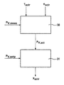
- FIG. 2 is a block circuit diagram illustrating a first exemplary embodiment of a method according to the invention.
- a pressure value for the current pressure of the pressure chamber 4 is detected from a detected actuator torque T actr which is detected (for example measured or derived directly from measurement variables) and a detected actuator position ⁇ actr (for example measured or derived directly from measurement variables) using a pressure model in block 30 as a basis.
- This pressure value is then passed on as an actual pressure P V,act to a controller 31 which determines actuation signals X actr for the electromechanical actuator of the pressure supplying device 20 in order to set or adjust the actual pressure P V,act to a predefined setpoint pressure P V,setp .
- the method according to the example therefore has a model-based detection (block 30 ) of pressure information (actual pressure P V,act ) on the basis of the motor variables of the actuator torque T actr and the actuator position ⁇ actr .
- the pressure information P V,act is then used to set/adjust pressures or pressure profiles of the pressure supplying device 20 by means of the immersion piston 3 which is driven by an electric motor.
- a pressure sensor (see for example pressure sensor 18 in FIG. 1 ) can be used which, however, has a finite pressure measuring range. Accordingly, only pressures between zero and the measuring range end value P meas,max can be measured by means of the pressure sensor (0 ⁇ P V,meas ⁇ P meas,max ).
- the current pressure of the pressure supplying device P V can be calculated from the actuator torque T actr and the actuator position ⁇ actr on the basis of the pressure model and can be used for control.
- the measured pressure P V,meas is also taken into account in block 30 .
- the measured pressure P V,meas can be included in the calculation of the actual pressure P V,act and/or in a determination or adaptation of one or more parameters of the pressure model.
- An example of the calculation of the actual pressure P V,act and an example of a pressure model are explained in more detail below.
- the exemplary model takes into account the components described in FIG. 1 of the electric motor 1 , transmission 2 and immersion piston 3 in a hydraulic pressure chamber 4 .
- the model describes the static and dynamic behavior of the motor 1 , which sets a corresponding motor torque T actr in order to generate the requested pressure P V,setp in the pressure chamber 4 .
- the parameters used in the model should be known sufficiently precisely.
- the parameters which describe the behavior of the friction are subject to certain changes which arise essentially owing to ambient conditions, variation and wear.
- the parameters which represent the friction are advantageously detected or corrected in the pressure ranges in which a valid pressure signal P V,meas which lies within the measuring range is present.
- a valid pressure signal P V,meas which lies within the measuring range is present.
- the detected motor torque T actr and the measured motor angle position ⁇ actr are used. If the pressure which is to be set in the hydraulic pressure chamber 4 is outside the measuring range P meas,max , pressure information P V,act is detected in a model-based fashion and set by means of the controller 31 by means of the corrected parameter and the still detectable variables of the motor torque T actr and motor angle position ⁇ actr .
- a model corresponding to equation (1) is used as the basis, thus the parameters which are to be updated during ongoing operation are the constant friction component M c which is dependent on the direction of rotation of the motor and the factor ⁇ which represents the influence of the load torque on M c .
- a pressure value P V,est corresponding to the equations (1) and (2) can be calculated as follows from the detected motor torque T actr and the measured motor angle position ⁇ actr :
- f 1 is the reverse function of the function f of equation (2).
- P V,est T hydr,est /K 1 (6)
- the index “est” characterizes here that the signals P V,est and T hydr,est are model signals which are calculated from motor signals.
- the torque T hydr is determined according to equation (2) or specifically equation (3) from the measured pressure P V,meas .
- a correction value for example the correction value ⁇ corr can also be selected/predefined as a function of the value of the deviation e (see equation (7)).
- two limiting values e 1 and e 2 can be predefined for the deviation e, with the result that the correction value ⁇ corr is then selected for the parameter ⁇ est as follows: for 0 ⁇
- ⁇ e 1 : ⁇ corr ⁇ corr,1 for e 1 ⁇
- ⁇ e 2 : ⁇ corr ⁇ corr,2 for e 2 ⁇
- : ⁇ corr ⁇ corr,3 (9)
- two threshold values P 1 and P 2 as well as a third threshold value P meas,max ⁇ P are predefined (as a function of the measuring range end value P meas,max ) for the pressure value of the pressure supplying device, wherein the following applies: 0 ⁇ P 1 ⁇ P 2 ⁇ P meas,max ⁇ P ⁇ P meas,max (10)
- the third threshold value P meas,max ⁇ AP is, according to the example, lower than the measuring range end value P meas,max by an amount equal to a safety pressure difference ⁇ P.
- the safety pressure difference ⁇ P is, for example, in the range of several bar.
- the variant parameters are detected or corrected in accordance with the description above, and otherwise (P V,meas >P 1 ) all the model parameters are maintained in their current state and a model-based detection of the pressure value P V,est is performed on the basis of the actuator signals of the motor torque T actr and motor angle position ⁇ actr , for example according to equations (4) and (5) and the associated description.
- the pressure signal P V,est which is obtained from the motor signals T actr , ⁇ actr is advantageously also supplied if a failure of the pressure sensor has been detected on the basis of a monitoring function.
Landscapes
- Engineering & Computer Science (AREA)
- Transportation (AREA)
- Mechanical Engineering (AREA)
- Braking Systems And Boosters (AREA)
- Valves And Accessory Devices For Braking Systems (AREA)
- Regulating Braking Force (AREA)
Abstract
Description
J·dω actr /dt=T actr −T hydr −d·ω actr−(M c +α·T hydr)·sign(ωactr)
where
- J: the overall moment of mass inertia to be overcome by the electric motor 1,
- ωactr: the motor angle speed which can be determined from the motor angle position φactr by differentiation,
- dωactr/dt: derivation of the motor angle speed over time,
- Tactr: the motor torque,
- d: a damping constant,
- Mc: the constant friction component which is dependent on the direction of rotation of the motor 1,
- Thydr: the torque which occurs on the basis of the hydraulic pressure PV, applied by the motor 1, in the pressure chamber 4, and acts as a load torque on the electric motor 1,
- α: factor, which takes into account the influence of the load torque Thydr on the static constant friction component Mc which is dependent on the direction of rotation of the motor,
- sign: sign function.
T hydr =f(P V), (2)
wherein the dependency function f is determined essentially by the transmission ratio of the transmission 2 and the cross section of the immersion piston 3.
T hydr =K 1 ·P V (3)
P V,est =T hydr,est /K 1 (6)
e=T actr −T actr,est (7)
where
T actr,est =J·dω actr /dt+T hydr +d·ω actr+(M c,est+αest ·T hydr)·sign(ωactr) (8)
for 0<|e|<e 1: Δαcorr=Δαcorr,1
for e 1 <|e|<e 2: Δαcorr=Δαcorr,2
for e 2 <|e|: Δα corr=Δαcorr,3 (9)
0<P 1 ≦P 2 <P meas,max −ΔP<P meas,max (10)
PV,act A=PV,meas.
P V,act B =λ·P V,meas+(1−λ)·P V,est.
λ=(P meas,max −ΔP−P V,meas)/(P meas,max −ΔP−P 2)
PV,act C=PV,est.
Claims (13)
Applications Claiming Priority (4)
| Application Number | Priority Date | Filing Date | Title |
|---|---|---|---|
| DE102011077313A DE102011077313A1 (en) | 2011-06-09 | 2011-06-09 | Method for operating a brake system and brake system |
| DE102011077313 | 2011-06-09 | ||
| DE102011077313.4 | 2011-06-09 | ||
| PCT/EP2012/056897 WO2012167980A1 (en) | 2011-06-09 | 2012-04-16 | Method for operating a brake system, and brake system |
Publications (2)
| Publication Number | Publication Date |
|---|---|
| US20140303865A1 US20140303865A1 (en) | 2014-10-09 |
| US9511752B2 true US9511752B2 (en) | 2016-12-06 |
Family
ID=45998321
Family Applications (1)
| Application Number | Title | Priority Date | Filing Date |
|---|---|---|---|
| US14/124,490 Active US9511752B2 (en) | 2011-06-09 | 2012-04-16 | Method for operating a brake system, and brake system |
Country Status (6)
| Country | Link |
|---|---|
| US (1) | US9511752B2 (en) |
| EP (1) | EP2718158B1 (en) |
| KR (1) | KR101924248B1 (en) |
| CN (1) | CN103608226B (en) |
| DE (1) | DE102011077313A1 (en) |
| WO (1) | WO2012167980A1 (en) |
Families Citing this family (12)
| Publication number | Priority date | Publication date | Assignee | Title |
|---|---|---|---|---|
| DE102013216329A1 (en) * | 2013-08-19 | 2015-02-19 | Continental Teves Ag & Co. Ohg | Method and device for controlling a brake system |
| KR102155831B1 (en) * | 2013-09-16 | 2020-09-14 | 현대모비스 주식회사 | Parking control system of emb and method thereof |
| FR3019953B1 (en) * | 2014-04-09 | 2016-05-06 | Staubli Sa Ets | METHOD FOR CONTROLLING A MULTI-AXIS AND ROBOT ROBOT FOR IMPLEMENTING SUCH A METHOD |
| KR20170031396A (en) * | 2015-09-11 | 2017-03-21 | 주식회사 만도 | Electric brake system |
| KR20170031405A (en) * | 2015-09-11 | 2017-03-21 | 주식회사 만도 | Electric brake system |
| EP3516472B1 (en) * | 2016-09-21 | 2022-08-31 | Valmet Flow Control Oy | Method and controller for actuator |
| KR102068995B1 (en) * | 2018-03-08 | 2020-02-11 | 주식회사 만도 | Electric brake system and controlling method thereof |
| EP4172030A4 (en) * | 2020-06-24 | 2024-07-10 | Ree Automotive Ltd. | Brake systems integrated into vehicle corner modules, and methods of use thereof |
| KR102812255B1 (en) * | 2020-12-31 | 2025-05-22 | 현대모비스 주식회사 | Brake System of Autonomous Driving Vehicle and Controlling Method thereof |
| CN113895417A (en) * | 2021-10-27 | 2022-01-07 | 平阳星嘉智能科技有限公司 | A method and device for estimating oil circuit hydraulic pressure in an electronic hydraulic brake-by-wire system |
| JP2025075722A (en) * | 2023-10-31 | 2025-05-15 | 株式会社アドヴィックス | electric braking device |
| DE102024206877A1 (en) * | 2024-07-22 | 2026-01-22 | Robert Bosch Gesellschaft mit beschränkter Haftung | Control device and method for operating a motorized brake pressure build-up device of a vehicle's braking system |
Citations (18)
| Publication number | Priority date | Publication date | Assignee | Title |
|---|---|---|---|---|
| US5051907A (en) * | 1988-12-24 | 1991-09-24 | Aisin Seiki K.K. | Anti-skid control system for an automotive vehicle |
| US5248191A (en) * | 1990-03-27 | 1993-09-28 | Nippondenso Co., Ltd. | Pressure control valve for continuous pressure control to wheel cylinder |
| US5249848A (en) * | 1991-09-17 | 1993-10-05 | Honda Giken Kogyo Kabushiki Kaisha | Method of and system for controlling brakes |
| US20020027388A1 (en) * | 2000-08-25 | 2002-03-07 | Wataru Tanaka | Brake control device for a vehicle |
| US20030160505A1 (en) * | 2002-02-22 | 2003-08-28 | Riddiford Bryan P. | Fast mode release in a force generating apparatus using estimated actuator apply chamber pressure |
| US20030214177A1 (en) * | 2002-05-16 | 2003-11-20 | Advics Co., Ltd. | Hydraulic brake system for vehicles |
| US20060087175A1 (en) * | 2004-10-22 | 2006-04-27 | Toyota Jidosha Kabushiki Kaisha | Brake system control apparatus |
| WO2006111393A1 (en) | 2005-04-21 | 2006-10-26 | Gerber, Wolfram | Pressure modulator control |
| US20070001629A1 (en) * | 2005-06-30 | 2007-01-04 | Mcgarry Jeremy T | System and method for locomotive adhesion control |
| US20070188015A1 (en) * | 2006-02-15 | 2007-08-16 | Advics Co., Ltd. | Vehicle brake control device |
| US20090228181A1 (en) * | 2003-05-08 | 2009-09-10 | Continental Teves Ag & Co. Ohg | Method and device for regulating the driving dynamics of a vehicle |
| DE102009033499A1 (en) | 2008-07-18 | 2010-01-21 | Continental Teves Ag & Co. Ohg | Brake system for motor vehicles |
| US20100256847A1 (en) * | 2008-01-22 | 2010-10-07 | Toyota Jidosha Kabushiki Kaisha | Vehicle body speed calculation device |
| WO2011029812A1 (en) | 2009-09-11 | 2011-03-17 | Continental Teves Ag & Co. Ohg | Braking system for motor vehicles and method for operating the same |
| US20110118920A1 (en) * | 2009-11-17 | 2011-05-19 | Hyundai Motor Company | Regenerative braking torque compensation device, methods for regenerative braking torque compensation and a hybrid vehicle embodying such devices and methods |
| US20110291469A1 (en) * | 2009-02-05 | 2011-12-01 | Continental Teves Ag & Co., Ohg | Method for operating a brake system |
| WO2011154369A1 (en) | 2010-06-10 | 2011-12-15 | Continental Teves Ag & Co. Ohg | Method and control circuit for controlling a braking system for motor vehicles |
| DE102012200705A1 (en) | 2011-01-27 | 2012-08-02 | Continental Teves Ag & Co. Ohg | Method and device for controlling an electro-hydraulic brake system |
Family Cites Families (3)
| Publication number | Priority date | Publication date | Assignee | Title |
|---|---|---|---|---|
| JP2008049800A (en) | 2006-08-24 | 2008-03-06 | Hitachi Ltd | Electric brake device and control method thereof |
| JP5074794B2 (en) * | 2007-03-17 | 2012-11-14 | 日立オートモティブシステムズ株式会社 | Brake control device |
| DE102009008944B4 (en) * | 2009-02-13 | 2024-03-14 | Ipgate Ag | Brake system with simultaneous or partially simultaneous pressure build-up and pressure reduction in the wheel brakes from different wheel cylinder pressure levels and method for setting a brake pressure |
-
2011
- 2011-06-09 DE DE102011077313A patent/DE102011077313A1/en not_active Withdrawn
-
2012
- 2012-04-16 EP EP12715951.5A patent/EP2718158B1/en active Active
- 2012-04-16 US US14/124,490 patent/US9511752B2/en active Active
- 2012-04-16 WO PCT/EP2012/056897 patent/WO2012167980A1/en not_active Ceased
- 2012-04-16 CN CN201280028292.9A patent/CN103608226B/en active Active
- 2012-04-16 KR KR1020147000565A patent/KR101924248B1/en active Active
Patent Citations (19)
| Publication number | Priority date | Publication date | Assignee | Title |
|---|---|---|---|---|
| US5051907A (en) * | 1988-12-24 | 1991-09-24 | Aisin Seiki K.K. | Anti-skid control system for an automotive vehicle |
| US5248191A (en) * | 1990-03-27 | 1993-09-28 | Nippondenso Co., Ltd. | Pressure control valve for continuous pressure control to wheel cylinder |
| US5249848A (en) * | 1991-09-17 | 1993-10-05 | Honda Giken Kogyo Kabushiki Kaisha | Method of and system for controlling brakes |
| US20020027388A1 (en) * | 2000-08-25 | 2002-03-07 | Wataru Tanaka | Brake control device for a vehicle |
| US20030160505A1 (en) * | 2002-02-22 | 2003-08-28 | Riddiford Bryan P. | Fast mode release in a force generating apparatus using estimated actuator apply chamber pressure |
| US20030214177A1 (en) * | 2002-05-16 | 2003-11-20 | Advics Co., Ltd. | Hydraulic brake system for vehicles |
| US20090228181A1 (en) * | 2003-05-08 | 2009-09-10 | Continental Teves Ag & Co. Ohg | Method and device for regulating the driving dynamics of a vehicle |
| US20060087175A1 (en) * | 2004-10-22 | 2006-04-27 | Toyota Jidosha Kabushiki Kaisha | Brake system control apparatus |
| WO2006111393A1 (en) | 2005-04-21 | 2006-10-26 | Gerber, Wolfram | Pressure modulator control |
| US20070001629A1 (en) * | 2005-06-30 | 2007-01-04 | Mcgarry Jeremy T | System and method for locomotive adhesion control |
| US20070188015A1 (en) * | 2006-02-15 | 2007-08-16 | Advics Co., Ltd. | Vehicle brake control device |
| US20100256847A1 (en) * | 2008-01-22 | 2010-10-07 | Toyota Jidosha Kabushiki Kaisha | Vehicle body speed calculation device |
| DE102009033499A1 (en) | 2008-07-18 | 2010-01-21 | Continental Teves Ag & Co. Ohg | Brake system for motor vehicles |
| US20110115282A1 (en) * | 2008-07-18 | 2011-05-19 | Dieter Dinkel | Brake system for motor vehicles |
| US20110291469A1 (en) * | 2009-02-05 | 2011-12-01 | Continental Teves Ag & Co., Ohg | Method for operating a brake system |
| WO2011029812A1 (en) | 2009-09-11 | 2011-03-17 | Continental Teves Ag & Co. Ohg | Braking system for motor vehicles and method for operating the same |
| US20110118920A1 (en) * | 2009-11-17 | 2011-05-19 | Hyundai Motor Company | Regenerative braking torque compensation device, methods for regenerative braking torque compensation and a hybrid vehicle embodying such devices and methods |
| WO2011154369A1 (en) | 2010-06-10 | 2011-12-15 | Continental Teves Ag & Co. Ohg | Method and control circuit for controlling a braking system for motor vehicles |
| DE102012200705A1 (en) | 2011-01-27 | 2012-08-02 | Continental Teves Ag & Co. Ohg | Method and device for controlling an electro-hydraulic brake system |
Non-Patent Citations (2)
| Title |
|---|
| German Examination Report-Aug. 31, 2012. |
| PCT International Search Report. |
Also Published As
| Publication number | Publication date |
|---|---|
| CN103608226A (en) | 2014-02-26 |
| EP2718158B1 (en) | 2015-07-01 |
| US20140303865A1 (en) | 2014-10-09 |
| DE102011077313A1 (en) | 2012-12-13 |
| CN103608226B (en) | 2016-04-06 |
| EP2718158A1 (en) | 2014-04-16 |
| KR101924248B1 (en) | 2018-11-30 |
| WO2012167980A1 (en) | 2012-12-13 |
| KR20140036303A (en) | 2014-03-25 |
Similar Documents
| Publication | Publication Date | Title |
|---|---|---|
| US9511752B2 (en) | Method for operating a brake system, and brake system | |
| CN102325676B (en) | Brake system having simultaneous or partially simultaneous pressure generation and reduction in the wheel brakes from differing wheel cylinder pressure levels | |
| US10442416B2 (en) | Electric brake system and method thereof | |
| US9604614B2 (en) | Method for operating a brake system, and brake system | |
| JP5734319B2 (en) | Brake device for vehicle | |
| US8914191B2 (en) | Method and control circuit for controlling a braking system for motor vehicles | |
| CN100591556C (en) | Brake controller and method for controlling braking | |
| CN102387949B (en) | Control device for a brake-boosted brake system of a motor vehicle and method for operating a brake-boosted brake system of a motor vehicle | |
| CN112977463B (en) | Device and method for estimating vehicle weight using vehicle height adjustment device | |
| US8620556B2 (en) | Correction method for the correction of characteristic curves for analogized hydraulic valves in motor vehicle braking systems | |
| US8239112B2 (en) | Pressure, tire force and friction estimation during antilock control | |
| KR970065268A (en) | Braking force control device | |
| JP2004515402A (en) | Device for detecting the risk of aquaplaning occurring during the driving mode of a vehicle | |
| JPH1170871A (en) | Control method and device for brake device | |
| JP6623952B2 (en) | Vehicle braking system | |
| KR102418890B1 (en) | Control device and method for operating an electromechanical brake booster of a brake system of a vehicle | |
| US6945613B1 (en) | Electrohydraulic brake system and methods for its control | |
| US8831850B2 (en) | Brake hydraulic control method and system | |
| CN114684084B (en) | Braking system of automatic driving vehicle and control method thereof | |
| JP6802908B2 (en) | Controls and methods for operating the electromechanical brake booster of a braking system designed to perform antilock control | |
| EP2371586A1 (en) | Method for controlling the fluidic actuation of a brake or suspension system | |
| US20110153177A1 (en) | Method and device for determining and balancing the working point of valves in a hydraulic system | |
| JP2010269771A (en) | Brake control device | |
| JP2011162121A (en) | Brake control device |
Legal Events
| Date | Code | Title | Description |
|---|---|---|---|
| AS | Assignment |
Owner name: CONTINENTAL TEVES AG & CO. OHG, GERMANY Free format text: ASSIGNMENT OF ASSIGNORS INTEREST;ASSIGNOR:BOHM, JURGEN;REEL/FRAME:033066/0032 Effective date: 20131218 |
|
| STCF | Information on status: patent grant |
Free format text: PATENTED CASE |
|
| FEPP | Fee payment procedure |
Free format text: PAYOR NUMBER ASSIGNED (ORIGINAL EVENT CODE: ASPN); ENTITY STATUS OF PATENT OWNER: LARGE ENTITY |
|
| MAFP | Maintenance fee payment |
Free format text: PAYMENT OF MAINTENANCE FEE, 4TH YEAR, LARGE ENTITY (ORIGINAL EVENT CODE: M1551); ENTITY STATUS OF PATENT OWNER: LARGE ENTITY Year of fee payment: 4 |
|
| MAFP | Maintenance fee payment |
Free format text: PAYMENT OF MAINTENANCE FEE, 8TH YEAR, LARGE ENTITY (ORIGINAL EVENT CODE: M1552); ENTITY STATUS OF PATENT OWNER: LARGE ENTITY Year of fee payment: 8 |
|
| AS | Assignment |
Owner name: CONTINENTAL AUTOMOTIVE TECHNOLOGIES GMBH, GERMANY Free format text: MERGER AND CHANGE OF NAME;ASSIGNORS:CONTINENTAL TEVES AG & CO. OHG;CONTINENTAL AUTOMOTIVE TECHNOLOGIES GMBH;REEL/FRAME:068794/0001 Effective date: 20220714 |