US9511751B2 - Object identification and active safety control for vehicles - Google Patents
Object identification and active safety control for vehicles Download PDFInfo
- Publication number
- US9511751B2 US9511751B2 US13/189,415 US201113189415A US9511751B2 US 9511751 B2 US9511751 B2 US 9511751B2 US 201113189415 A US201113189415 A US 201113189415A US 9511751 B2 US9511751 B2 US 9511751B2
- Authority
- US
- United States
- Prior art keywords
- target object
- vehicle
- predetermined threshold
- motor vehicle
- host vehicle
- Prior art date
- Legal status (The legal status is an assumption and is not a legal conclusion. Google has not performed a legal analysis and makes no representation as to the accuracy of the status listed.)
- Active, expires
Links
- 238000000034 method Methods 0.000 claims abstract description 91
- 238000001514 detection method Methods 0.000 claims description 33
- 230000009471 action Effects 0.000 claims description 21
- 230000008859 change Effects 0.000 claims description 14
- 230000001960 triggered effect Effects 0.000 claims 2
- 230000008569 process Effects 0.000 description 37
- 238000004891 communication Methods 0.000 description 23
- 230000001133 acceleration Effects 0.000 description 18
- 238000004364 calculation method Methods 0.000 description 11
- 238000002485 combustion reaction Methods 0.000 description 7
- 238000012545 processing Methods 0.000 description 7
- 238000005259 measurement Methods 0.000 description 6
- 230000000007 visual effect Effects 0.000 description 6
- 230000005540 biological transmission Effects 0.000 description 4
- 230000006870 function Effects 0.000 description 4
- 230000000977 initiatory effect Effects 0.000 description 4
- LYCAIKOWRPUZTN-UHFFFAOYSA-N Ethylene glycol Chemical compound OCCO LYCAIKOWRPUZTN-UHFFFAOYSA-N 0.000 description 3
- 238000010586 diagram Methods 0.000 description 3
- 230000001629 suppression Effects 0.000 description 3
- LFQSCWFLJHTTHZ-UHFFFAOYSA-N Ethanol Chemical compound CCO LFQSCWFLJHTTHZ-UHFFFAOYSA-N 0.000 description 2
- 239000002826 coolant Substances 0.000 description 2
- 239000012809 cooling fluid Substances 0.000 description 2
- VNWKTOKETHGBQD-UHFFFAOYSA-N methane Chemical compound C VNWKTOKETHGBQD-UHFFFAOYSA-N 0.000 description 2
- 230000003287 optical effect Effects 0.000 description 2
- 238000002360 preparation method Methods 0.000 description 2
- 230000000246 remedial effect Effects 0.000 description 2
- 230000001755 vocal effect Effects 0.000 description 2
- UFHFLCQGNIYNRP-UHFFFAOYSA-N Hydrogen Chemical compound [H][H] UFHFLCQGNIYNRP-UHFFFAOYSA-N 0.000 description 1
- HBBGRARXTFLTSG-UHFFFAOYSA-N Lithium ion Chemical compound [Li+] HBBGRARXTFLTSG-UHFFFAOYSA-N 0.000 description 1
- 230000002528 anti-freeze Effects 0.000 description 1
- 150000001875 compounds Chemical class 0.000 description 1
- 238000001816 cooling Methods 0.000 description 1
- 230000003247 decreasing effect Effects 0.000 description 1
- 230000001419 dependent effect Effects 0.000 description 1
- 238000004146 energy storage Methods 0.000 description 1
- 238000005516 engineering process Methods 0.000 description 1
- 230000007613 environmental effect Effects 0.000 description 1
- 230000005294 ferromagnetic effect Effects 0.000 description 1
- 239000000835 fiber Substances 0.000 description 1
- 239000000446 fuel Substances 0.000 description 1
- 230000005484 gravity Effects 0.000 description 1
- 239000001257 hydrogen Substances 0.000 description 1
- 229910052739 hydrogen Inorganic materials 0.000 description 1
- 229910001416 lithium ion Inorganic materials 0.000 description 1
- GELKBWJHTRAYNV-UHFFFAOYSA-K lithium iron phosphate Chemical compound [Li+].[Fe+2].[O-]P([O-])([O-])=O GELKBWJHTRAYNV-UHFFFAOYSA-K 0.000 description 1
- 230000007246 mechanism Effects 0.000 description 1
- 239000000203 mixture Substances 0.000 description 1
- 238000012544 monitoring process Methods 0.000 description 1
- 239000003345 natural gas Substances 0.000 description 1
- 230000004044 response Effects 0.000 description 1
- 230000003068 static effect Effects 0.000 description 1
- 239000013589 supplement Substances 0.000 description 1
- XLYOFNOQVPJJNP-UHFFFAOYSA-N water Substances O XLYOFNOQVPJJNP-UHFFFAOYSA-N 0.000 description 1
Images


Classifications
-
- B—PERFORMING OPERATIONS; TRANSPORTING
- B60—VEHICLES IN GENERAL
- B60T—VEHICLE BRAKE CONTROL SYSTEMS OR PARTS THEREOF; BRAKE CONTROL SYSTEMS OR PARTS THEREOF, IN GENERAL; ARRANGEMENT OF BRAKING ELEMENTS ON VEHICLES IN GENERAL; PORTABLE DEVICES FOR PREVENTING UNWANTED MOVEMENT OF VEHICLES; VEHICLE MODIFICATIONS TO FACILITATE COOLING OF BRAKES
- B60T7/00—Brake-action initiating means
- B60T7/12—Brake-action initiating means for automatic initiation; for initiation not subject to will of driver or passenger
- B60T7/22—Brake-action initiating means for automatic initiation; for initiation not subject to will of driver or passenger initiated by contact of vehicle, e.g. bumper, with an external object, e.g. another vehicle, or by means of contactless obstacle detectors mounted on the vehicle
-
- B—PERFORMING OPERATIONS; TRANSPORTING
- B60—VEHICLES IN GENERAL
- B60W—CONJOINT CONTROL OF VEHICLE SUB-UNITS OF DIFFERENT TYPE OR DIFFERENT FUNCTION; CONTROL SYSTEMS SPECIALLY ADAPTED FOR HYBRID VEHICLES; ROAD VEHICLE DRIVE CONTROL SYSTEMS FOR PURPOSES NOT RELATED TO THE CONTROL OF A PARTICULAR SUB-UNIT
- B60W10/00—Conjoint control of vehicle sub-units of different type or different function
- B60W10/18—Conjoint control of vehicle sub-units of different type or different function including control of braking systems
- B60W10/184—Conjoint control of vehicle sub-units of different type or different function including control of braking systems with wheel brakes
-
- B—PERFORMING OPERATIONS; TRANSPORTING
- B60—VEHICLES IN GENERAL
- B60W—CONJOINT CONTROL OF VEHICLE SUB-UNITS OF DIFFERENT TYPE OR DIFFERENT FUNCTION; CONTROL SYSTEMS SPECIALLY ADAPTED FOR HYBRID VEHICLES; ROAD VEHICLE DRIVE CONTROL SYSTEMS FOR PURPOSES NOT RELATED TO THE CONTROL OF A PARTICULAR SUB-UNIT
- B60W10/00—Conjoint control of vehicle sub-units of different type or different function
- B60W10/20—Conjoint control of vehicle sub-units of different type or different function including control of steering systems
-
- B—PERFORMING OPERATIONS; TRANSPORTING
- B60—VEHICLES IN GENERAL
- B60W—CONJOINT CONTROL OF VEHICLE SUB-UNITS OF DIFFERENT TYPE OR DIFFERENT FUNCTION; CONTROL SYSTEMS SPECIALLY ADAPTED FOR HYBRID VEHICLES; ROAD VEHICLE DRIVE CONTROL SYSTEMS FOR PURPOSES NOT RELATED TO THE CONTROL OF A PARTICULAR SUB-UNIT
- B60W30/00—Purposes of road vehicle drive control systems not related to the control of a particular sub-unit, e.g. of systems using conjoint control of vehicle sub-units
- B60W30/08—Active safety systems predicting or avoiding probable or impending collision or attempting to minimise its consequences
- B60W30/09—Taking automatic action to avoid collision, e.g. braking and steering
-
- B—PERFORMING OPERATIONS; TRANSPORTING
- B60—VEHICLES IN GENERAL
- B60W—CONJOINT CONTROL OF VEHICLE SUB-UNITS OF DIFFERENT TYPE OR DIFFERENT FUNCTION; CONTROL SYSTEMS SPECIALLY ADAPTED FOR HYBRID VEHICLES; ROAD VEHICLE DRIVE CONTROL SYSTEMS FOR PURPOSES NOT RELATED TO THE CONTROL OF A PARTICULAR SUB-UNIT
- B60W30/00—Purposes of road vehicle drive control systems not related to the control of a particular sub-unit, e.g. of systems using conjoint control of vehicle sub-units
- B60W30/08—Active safety systems predicting or avoiding probable or impending collision or attempting to minimise its consequences
- B60W30/095—Predicting travel path or likelihood of collision
- B60W30/0956—Predicting travel path or likelihood of collision the prediction being responsive to traffic or environmental parameters
-
- G—PHYSICS
- G08—SIGNALLING
- G08G—TRAFFIC CONTROL SYSTEMS
- G08G1/00—Traffic control systems for road vehicles
- G08G1/16—Anti-collision systems
- G08G1/166—Anti-collision systems for active traffic, e.g. moving vehicles, pedestrians, bikes
-
- B—PERFORMING OPERATIONS; TRANSPORTING
- B60—VEHICLES IN GENERAL
- B60W—CONJOINT CONTROL OF VEHICLE SUB-UNITS OF DIFFERENT TYPE OR DIFFERENT FUNCTION; CONTROL SYSTEMS SPECIALLY ADAPTED FOR HYBRID VEHICLES; ROAD VEHICLE DRIVE CONTROL SYSTEMS FOR PURPOSES NOT RELATED TO THE CONTROL OF A PARTICULAR SUB-UNIT
- B60W10/00—Conjoint control of vehicle sub-units of different type or different function
- B60W10/18—Conjoint control of vehicle sub-units of different type or different function including control of braking systems
-
- B—PERFORMING OPERATIONS; TRANSPORTING
- B60—VEHICLES IN GENERAL
- B60W—CONJOINT CONTROL OF VEHICLE SUB-UNITS OF DIFFERENT TYPE OR DIFFERENT FUNCTION; CONTROL SYSTEMS SPECIALLY ADAPTED FOR HYBRID VEHICLES; ROAD VEHICLE DRIVE CONTROL SYSTEMS FOR PURPOSES NOT RELATED TO THE CONTROL OF A PARTICULAR SUB-UNIT
- B60W2520/00—Input parameters relating to overall vehicle dynamics
- B60W2520/10—Longitudinal speed
-
- B—PERFORMING OPERATIONS; TRANSPORTING
- B60—VEHICLES IN GENERAL
- B60W—CONJOINT CONTROL OF VEHICLE SUB-UNITS OF DIFFERENT TYPE OR DIFFERENT FUNCTION; CONTROL SYSTEMS SPECIALLY ADAPTED FOR HYBRID VEHICLES; ROAD VEHICLE DRIVE CONTROL SYSTEMS FOR PURPOSES NOT RELATED TO THE CONTROL OF A PARTICULAR SUB-UNIT
- B60W2540/00—Input parameters relating to occupants
- B60W2540/18—Steering angle
-
- B60W2550/302—
-
- B60W2550/304—
-
- B60W2550/306—
-
- B—PERFORMING OPERATIONS; TRANSPORTING
- B60—VEHICLES IN GENERAL
- B60W—CONJOINT CONTROL OF VEHICLE SUB-UNITS OF DIFFERENT TYPE OR DIFFERENT FUNCTION; CONTROL SYSTEMS SPECIALLY ADAPTED FOR HYBRID VEHICLES; ROAD VEHICLE DRIVE CONTROL SYSTEMS FOR PURPOSES NOT RELATED TO THE CONTROL OF A PARTICULAR SUB-UNIT
- B60W2554/00—Input parameters relating to objects
- B60W2554/40—Dynamic objects, e.g. animals, windblown objects
- B60W2554/404—Characteristics
- B60W2554/4041—Position
-
- B—PERFORMING OPERATIONS; TRANSPORTING
- B60—VEHICLES IN GENERAL
- B60W—CONJOINT CONTROL OF VEHICLE SUB-UNITS OF DIFFERENT TYPE OR DIFFERENT FUNCTION; CONTROL SYSTEMS SPECIALLY ADAPTED FOR HYBRID VEHICLES; ROAD VEHICLE DRIVE CONTROL SYSTEMS FOR PURPOSES NOT RELATED TO THE CONTROL OF A PARTICULAR SUB-UNIT
- B60W2554/00—Input parameters relating to objects
- B60W2554/80—Spatial relation or speed relative to objects
- B60W2554/803—Relative lateral speed
-
- B—PERFORMING OPERATIONS; TRANSPORTING
- B60—VEHICLES IN GENERAL
- B60W—CONJOINT CONTROL OF VEHICLE SUB-UNITS OF DIFFERENT TYPE OR DIFFERENT FUNCTION; CONTROL SYSTEMS SPECIALLY ADAPTED FOR HYBRID VEHICLES; ROAD VEHICLE DRIVE CONTROL SYSTEMS FOR PURPOSES NOT RELATED TO THE CONTROL OF A PARTICULAR SUB-UNIT
- B60W2554/00—Input parameters relating to objects
- B60W2554/80—Spatial relation or speed relative to objects
- B60W2554/804—Relative longitudinal speed
-
- B—PERFORMING OPERATIONS; TRANSPORTING
- B60—VEHICLES IN GENERAL
- B60W—CONJOINT CONTROL OF VEHICLE SUB-UNITS OF DIFFERENT TYPE OR DIFFERENT FUNCTION; CONTROL SYSTEMS SPECIALLY ADAPTED FOR HYBRID VEHICLES; ROAD VEHICLE DRIVE CONTROL SYSTEMS FOR PURPOSES NOT RELATED TO THE CONTROL OF A PARTICULAR SUB-UNIT
- B60W2720/00—Output or target parameters relating to overall vehicle dynamics
- B60W2720/10—Longitudinal speed
-
- B—PERFORMING OPERATIONS; TRANSPORTING
- B60—VEHICLES IN GENERAL
- B60W—CONJOINT CONTROL OF VEHICLE SUB-UNITS OF DIFFERENT TYPE OR DIFFERENT FUNCTION; CONTROL SYSTEMS SPECIALLY ADAPTED FOR HYBRID VEHICLES; ROAD VEHICLE DRIVE CONTROL SYSTEMS FOR PURPOSES NOT RELATED TO THE CONTROL OF A PARTICULAR SUB-UNIT
- B60W2720/00—Output or target parameters relating to overall vehicle dynamics
- B60W2720/12—Lateral speed
-
- B60W2750/302—
-
- B60W2750/304—
-
- B60W2750/308—
-
- B—PERFORMING OPERATIONS; TRANSPORTING
- B60—VEHICLES IN GENERAL
- B60W—CONJOINT CONTROL OF VEHICLE SUB-UNITS OF DIFFERENT TYPE OR DIFFERENT FUNCTION; CONTROL SYSTEMS SPECIALLY ADAPTED FOR HYBRID VEHICLES; ROAD VEHICLE DRIVE CONTROL SYSTEMS FOR PURPOSES NOT RELATED TO THE CONTROL OF A PARTICULAR SUB-UNIT
- B60W2754/00—Output or target parameters relating to objects
- B60W2754/10—Spatial relation or speed relative to objects
- B60W2754/30—Longitudinal distance
-
- B—PERFORMING OPERATIONS; TRANSPORTING
- B60—VEHICLES IN GENERAL
- B60W—CONJOINT CONTROL OF VEHICLE SUB-UNITS OF DIFFERENT TYPE OR DIFFERENT FUNCTION; CONTROL SYSTEMS SPECIALLY ADAPTED FOR HYBRID VEHICLES; ROAD VEHICLE DRIVE CONTROL SYSTEMS FOR PURPOSES NOT RELATED TO THE CONTROL OF A PARTICULAR SUB-UNIT
- B60W2754/00—Output or target parameters relating to objects
- B60W2754/10—Spatial relation or speed relative to objects
- B60W2754/40—Relative lateral speed
-
- B—PERFORMING OPERATIONS; TRANSPORTING
- B60—VEHICLES IN GENERAL
- B60W—CONJOINT CONTROL OF VEHICLE SUB-UNITS OF DIFFERENT TYPE OR DIFFERENT FUNCTION; CONTROL SYSTEMS SPECIALLY ADAPTED FOR HYBRID VEHICLES; ROAD VEHICLE DRIVE CONTROL SYSTEMS FOR PURPOSES NOT RELATED TO THE CONTROL OF A PARTICULAR SUB-UNIT
- B60W2754/00—Output or target parameters relating to objects
- B60W2754/10—Spatial relation or speed relative to objects
- B60W2754/50—Relative longitudinal speed
Definitions
- the present disclosure generally relates to the field of vehicles and, more specifically, to methods and systems for identifying objects proximate vehicles and for controlling active safety features for vehicles.
- FCA forward collision alert
- CPS collision preparation system
- ECA enhanced collision avoidance
- active safety functionality supplements traditional driver control of the vehicle with one or more warnings or automated actions, such as automatic braking and/or steering, in appropriate conditions, such as when another vehicle or object is detected in proximity to the vehicle. While active safety functionality serves valuable purposes, it may be desirable to tailor the active safety actions to particular types of detected objects, and/or to classify different types of detected objects.
- a method for identifying objects in proximity to a host vehicle. The method comprises the steps of detecting a target object in proximity to the host vehicle, measuring a movement of the target object, and classifying the target object based at least in part on the movement of the target object using a processor.
- a method for controlling an active safety system for a host vehicle.
- the method comprises the steps of identifying a target object in proximity to the host vehicle, calculating a time to collision between the target object and the host vehicle via a processor, implementing the active safety system if the time to collision is less than a first predetermined threshold if the target object is identified as comprising a motor vehicle, and implementing the active safety system if the time to collision is less than a second predetermined threshold if the target object is identified as comprising an individual not in a motor vehicle, the second predetermined threshold being greater than the first predetermined threshold.
- a vehicle comprising a drive system and an active safety system.
- the active safety system is coupled to the drive system, and is configured to provide an action during a drive cycle of the vehicle.
- the active safety system comprises a detection unit and a processor.
- the detection unit is configured to detect a target object in proximity to the vehicle and measure a movement of the target object.
- the processor is coupled to the detection unit.
- the processor is configured to classify the target object based at least in part on the movement of the target object for use in providing the action of the active safety system.
- FIG. 1 is a functional block diagram of a vehicle that includes an active safety control system, in accordance with an exemplary embodiment
- FIG. 2 is a functional block diagram of an active safety control system that can be used in connection with the vehicle of FIG. 1 , in accordance with an exemplary embodiment
- FIG. 3 is a flowchart of a process for identifying objects in proximity to a vehicle and controlling an active safety control system of the vehicle, and that can be used in connection with the vehicle of FIG. 1 and the active safety control system of FIGS. 1 and 2 , in accordance with an exemplary embodiment;
- FIG. 4 is a flowchart of a sub-process of the process of FIG. 3 , namely, the sub-process of classifying an object as a target vehicle in proximity to the host vehicle, and controlling active safety functionality of the vehicle accordingly, in accordance with an exemplary embodiment;
- FIG. 5 is a flowchart of another sub-process of the process of FIG. 3 , namely, the sub-process of classifying an object as comprising an individual not in a motor vehicle, in proximity to the host vehicle, in accordance with an exemplary embodiment;
- FIG. 6 is a schematic drawing illustration of the vehicle of FIG. 1 travelling within a road lane in proximity to possible objects, in accordance with an exemplary embodiment.
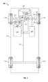
- FIG. 1 illustrates a vehicle 100 , or automobile, according to an exemplary embodiment.
- the vehicle 100 is also referenced at various points throughout this application as the host vehicle.
- the vehicle 100 includes an active safety control system (“ASCS”) 170 for identification of objects proximate the host vehicle and for optimized control of active safety functionality for the vehicle 100 that is based at least in part on the identification of the objects proximate the host vehicle.
- ASCS active safety control system
- the vehicle 100 is travelling within a lane 602 of a road or other path in a direction 603 .
- the vehicle 100 may be surrounded by one or more objects 604 .
- the objects 604 may comprise other vehicles (such as automobiles), pedestrians, bicycles, and/or other objects, individuals, and/or devices.
- Such objects are referenced at various points throughout this application as objects or target objects.
- the vehicle 100 includes a chassis 112 , a body 114 , four wheels 116 , an electronic control system 118 , a steering system 150 , a braking system 160 , and an active safety control system 170 .
- the body 114 is arranged on the chassis 112 and substantially encloses the other components of the vehicle 100 .
- the body 114 and the chassis 112 may jointly form a frame.
- the wheels 116 are each rotationally coupled to the chassis 112 near a respective corner of the body 114 .
- the vehicle 100 may be any one of a number of different types of automobiles, such as, for example, a sedan, a wagon, a truck, or a sport utility vehicle (SUV), and may be two-wheel drive (2WD) (i.e., rear-wheel drive or front-wheel drive), four-wheel drive (4WD) or all-wheel drive (AWD).
- 2WD two-wheel drive
- 4WD four-wheel drive
- ATD all-wheel drive
- the vehicle 100 may also incorporate any one of, or combination of, a number of different types of electrical propulsion systems, such as, for example, a gasoline or diesel fueled combustion engine, a “flex fuel vehicle” (FFV) engine (i.e., using a mixture of gasoline and ethanol), a gaseous compound (e.g., hydrogen or natural gas) fueled engine, a combustion/electric motor hybrid engine, and an electric motor.
- a gasoline or diesel fueled combustion engine a “flex fuel vehicle” (FFV) engine (i.e., using a mixture of gasoline and ethanol)
- a gaseous compound e.g., hydrogen or natural gas
- the vehicle 100 is a hybrid electric vehicle (HEV), and further includes an actuator assembly 120 , an energy storage system (ESS) 122 , a power inverter assembly (or inverter) 126 , and a radiator 128 .
- the actuator assembly 120 includes at least one electric propulsion system 129 mounted on the chassis 112 that drives the wheels 116 .
- the actuator assembly 120 includes a combustion engine 130 and an electric motor/generator (or motor) 132 .
- the electric motor 132 includes a transmission therein, and, although not illustrated, also includes a stator assembly (including conductive coils), a rotor assembly (including a ferromagnetic core), and a cooling fluid or coolant.
- the stator assembly and/or the rotor assembly within the electric motor 132 may include multiple electromagnetic poles, as is commonly understood.
- the combustion engine 130 and the electric motor 132 are integrated such that one or both are mechanically coupled to at least some of the wheels 116 through one or more drive shafts 134 .
- the vehicle 100 is a “series HEV,” in which the combustion engine 130 is not directly coupled to the transmission, but coupled to a generator (not shown), which is used to power the electric motor 132 .
- the vehicle 100 is a “parallel HEV,” in which the combustion engine 130 is directly coupled to the transmission by, for example, having the rotor of the electric motor 132 rotationally coupled to the drive shaft of the combustion engine 130 .
- the ESS 122 is mounted on the chassis 112 , and is electrically connected to the inverter 126 .
- the ESS 122 preferably comprises a battery having a pack of battery cells.
- the ESS 122 comprises a lithium iron phosphate battery, such as a nanophosphate lithium ion battery.
- the ESS 122 and electric propulsion system(s) 129 provide a drive system to propel the vehicle 100 .
- the radiator 128 is connected to the frame at an outer portion thereof and although not illustrated in detail, includes multiple cooling channels therein that contain a cooling fluid (i.e., coolant) such as water and/or ethylene glycol (i.e., “antifreeze”) and is coupled to the engine 130 and the inverter 126 .
- a cooling fluid i.e., coolant
- coolant such as water and/or ethylene glycol (i.e., “antifreeze”
- the steering system 150 is mounted on the chassis 112 , and controls steering of the wheels 116 .
- the steering system 150 includes a steering wheel and a steering column (not depicted).
- the steering wheel receives inputs from a driver of the vehicle.
- the steering column results in desired steering angles for the wheels 116 via the drive shafts 134 based on the inputs from the driver.
- the braking system 160 is mounted on the chassis 112 , and provides braking for the vehicle 100 .
- the braking system 160 receives inputs from the driver via a brake pedal (not depicted), and provides appropriate braking via brake units (also not depicted).
- the driver also provides inputs via an accelerator pedal (not depicted) as to a desired speed or acceleration of the vehicle, as well as various other inputs for various vehicle devices and/or systems, such as one or more vehicle radios, other entertainment systems, environmental control systems, lightning units, navigation systems, and the like (also not depicted).
- the ASCS 170 is mounted on the chassis 112 .
- the ASCS 170 may be coupled to various other vehicle devices and systems, such as, among others, the actuator assembly 120 , the steering system 150 , the braking system 160 , and the electronic control system 118 .
- the ASCS 170 identifies objects proximate to the vehicle and provides various active safety controls (including adjustments for active safety systems such as automatic braking systems such as collision preparation systems (CPS), automatic steering systems such as enhanced collision avoidance (ECS) systems, and forward collision alert (FCA) systems) based at least in part on the identification of the objects in proximity to the vehicle.
- active safety controls including adjustments for active safety systems such as automatic braking systems such as collision preparation systems (CPS), automatic steering systems such as enhanced collision avoidance (ECS) systems, and forward collision alert (FCA) systems
- the ASCS 170 (and/or one or more components thereof) may be integral with the electronic control system 118 and may also include one or more power sources.
- the ASCS 170 preferably conducts various steps of the process 300 and the steps and sub-processes thereof of FIGS. 3-5 .
- the ASCS 170 includes an object detection unit 202 , a communication unit 204 , a sensor array 206 , a driver notification unit 208 , and a controller 210 .
- the object detection unit 202 is used to detect objects in proximity to the vehicle, and to obtain information and data pertaining thereto (such as information and data pertaining to position and movement of the objects).
- the object detection unit 202 provides these various types of information to the controller 210 for processing and for use in identifying/classifying the objects detected by the object detection unit 202 for use in controlling the active safety functionality for the vehicle.
- the object detection unit 202 includes one or more cameras 212 and/or other vision-based detection devices, radar devices 214 (such as long and short range radar detection devices), and/or other object detection devices 216 such as, by way of example, light detection and ranging (LIDAR).
- LIDAR light detection and ranging
- the communication unit 204 receives information regarding data as to position, movement, and operation of the vehicle and/or pertaining to objects in proximity to the vehicle. Specifically, in one embodiment, the communication unit 204 receives information as to one or more of the following: driver inputs for an accelerator pedal of the vehicle, driver inputs for a brake pedal of the vehicle, a driver's engagement of a steering wheel of the vehicle, information as to lateral and longitudinal positions, velocities, and accelerations of the vehicle, and information as to lateral and longitudinal positions, velocities, and accelerations of objects in proximity to the vehicle.
- the communication unit 204 provides these various types of information to the controller 210 for processing and for use in identifying/classifying the objects detected by the object detection unit 202 for use in controlling the active safety functionality for the vehicle. Per the discussion further below, in certain embodiments, some or all of this information may be provided instead by the sensor array 206 .
- a longitudinal position of a vehicle or object comprises a position of the vehicle or object with respect to a longitudinal direction of movement of the host vehicle;
- a longitudinal velocity of a vehicle or object comprises a velocity of the vehicle or object with respect to a longitudinal direction of movement of the host vehicle;
- a longitudinal acceleration of a vehicle or object comprises a component of an acceleration of the vehicle or object with respect to a longitudinal direction of movement of the host vehicle.
- a lateral position of a vehicle or object comprises a position of the vehicle or object that is perpendicular to a longitudinal direction of movement of the host vehicle;
- a lateral velocity of a vehicle or object comprises a velocity of the vehicle or object that is perpendicular to a longitudinal direction of movement of the host vehicle;
- a lateral acceleration of a vehicle or object comprises a component of an acceleration of the vehicle or object that is perpendicular to a longitudinal direction of movement of the host vehicle.
- the communication unit 204 includes an internal communication device 222 and an external communication device 224 .
- the internal communication device 222 preferably comprises a transceiver configured to receive various of the above information from various other devices and systems of the vehicle, outside of the ASCS 170 , via a vehicle communications bus (not depicted).
- the external communication device 224 preferably comprises a transceiver (such as a vehicle telematics unit and/or a global system (GPS) device) configured to receive various of the above information from a central database and/or from a satellite system via a wireless network (not depicted).
- GPS global system
- the sensor array 206 measures parameters for data as to operating conditions and usage of the vehicle.
- the sensor array 206 comprises various sensors 230 that measure values of parameters pertaining to one or more of the following: driver inputs for an accelerator pedal of the vehicle, driver inputs for a brake pedal of the vehicle, a driver's engagement of a steering wheel of the vehicle, and information as to lateral and longitudinal positions, velocities, and accelerations of the vehicle, and information as to lateral and longitudinal positions, velocities, and accelerations of objects in proximity to the vehicle.
- the sensor array 206 provides these various types of information to the controller 210 for processing and for use in identifying/classifying the objects detected by the object detection unit 202 for use in controlling the active safety functionality for the vehicle. Per the discussion above, in certain embodiments, some or all of this information may be provided instead by the communication unit 204 . As depicted in FIG. 2 , the sensor array 206 includes one or more brake pedal sensors 232 , accelerator pedal sensors 234 , steering angle sensors 236 , wheel speed sensors 238 , yaw rate sensors, and/or accelerometers 240 .
- the brake pedal sensors 232 are coupled to or part of the braking system 160 of FIG. 1 .
- the brake pedal sensors 232 include one or more brake pedal position sensors and/or brake pedal travel sensors.
- the brake pedal position sensor measures a position of the brake pedal or an indication as to how far the brake pedal has traveled when the operator applies force to the brake pedal.
- the brake pedal force sensor measures an amount of force applied to the brake pedal by the driver of the vehicle.
- the accelerator pedal sensors 234 are coupled to an accelerator pedal of the vehicle.
- the accelerator pedal sensors 234 include one or more accelerator pedal position sensors and/or accelerator pedal travel sensors.
- the accelerator pedal position sensor measures a position of the accelerator pedal or an indication as to how far the accelerator pedal has traveled when the operator applies force to the accelerator pedal.
- the accelerator pedal force sensor measures an amount of force applied to the accelerator pedal by the driver of the vehicle.
- the steering angle sensors 236 are coupled to or part of the steering system 150 of FIG. 1 , and are preferably coupled to a steering wheel or steering column thereof.
- the steering angle sensors 236 measure an angular position of the steering column and/or steering wheel or an indication as to how far the steering column is turned when the operator applies force to a steering wheel of the steering column.
- the wheel speed sensors 238 are coupled to one or more of the wheels 116 of FIG. 1 .
- the wheel speed sensors 238 measure wheel speeds of the wheels 115 while the vehicle is being operated.
- each wheel speed sensor 238 measures a speed (or velocity) of a different respective wheel 116 .
- the accelerometers 240 measure an acceleration of the vehicle. In certain embodiments, the accelerometers measure lateral and longitudinal acceleration of the vehicle. In certain other embodiments, vehicle acceleration values are instead calculated by the controller 210 using velocity values, for example as calculated using the wheel speed values obtained from the wheel speed sensors 238 .
- the driver notification unit 208 provides notifications/alerts/warnings to the driver and other occupants of the vehicle when an object is identified in proximity to the vehicle as potentially posing a threat to the vehicle.
- the display unit provides notifications/alerts/warnings when an expected or calculated time to collision between an object and the vehicle is less than one or more predetermined thresholds that are preferably stored in the memory 252 of FIG. 2 as stored values 262 thereof.
- the driver notification unit 208 includes an audio component 242 and a visual component 244 .
- the audio component 242 provides audio notifications/alerts/warnings (such as an audible alarm, a beeping sound, or a verbal description that an object is nearby or a collision may be imminent) to the driver and/or other occupants of the vehicle.
- the visual component 244 provides visual notifications/alerts/warnings (such as an illuminated light, a flashing light, or a visual description that an object is nearby or a collision may be imminent) to the driver and/or other occupants of the vehicle.
- the controller 210 is coupled to the object detection unit 202 , the communication unit 204 , the sensor array 206 , and the driver notification unit 208 .
- the controller 210 processes the data and information received from the object detection unit 202 , the communication unit 204 , and the sensor array 206 .
- the controller 210 identifies/classifies objects in proximity to the vehicle that are detected by the object detection unit 202 using data and information obtained from the object detection unit 202 , the communication unit 204 , and/or the sensor array 206 .
- the controller 210 also utilizes the identification/classification of the objects in proximity to the vehicle to provide appropriate notifications/alerts/warnings via instructions provided to the driver notification unit 208 and also to control one or more aspects of active safety control (such as automatic steering and/or automatic braking) via instructions provided to the steering system 150 and/or the braking system 160 of FIG. 1 .
- the controller 210 performs these functions in accordance with steps of the process 300 (and sub-processes and/or sub-steps thereof) described further below in connection with FIGS. 3-5 .
- the controller 210 comprises a computer system.
- the controller 210 may also include one or more of the object detection unit 202 , the communication unit 204 , the sensor array 206 , the driver notification unit 208 , and/or components thereof.
- the controller 210 may otherwise differ from the embodiment depicted in FIG. 2 .
- the controller 210 may be coupled to or may otherwise utilize one or more remote computer systems and/or other control systems.
- the computer system of the controller 210 includes a processor 250 , a memory 252 , an interface 254 , a storage device 256 , and a bus 258 .
- the processor 250 performs the computation and control functions of the controller 210 , and may comprise any type of processor or multiple processors, single integrated circuits such as a microprocessor, or any suitable number of integrated circuit devices and/or circuit boards working in cooperation to accomplish the functions of a processing unit.
- the processor 250 executes one or more programs 260 contained within the memory 252 and, as such, controls the general operation of the controller 210 and the computer system of the controller 210 , preferably in executing the steps of the processes described herein, such as the steps of the process 300 (and any sub-processes thereof) in connection with FIGS. 3-5 .
- the memory 252 can be any type of suitable memory. This would include the various types of dynamic random access memory (DRAM) such as SDRAM, the various types of static RAM (SRAM), and the various types of non-volatile memory (PROM, EPROM, and flash). In certain examples, the memory 252 is located on and/or co-located on the same computer chip as the processor 250 . In the depicted embodiment, the memory 252 stores the above-referenced program 260 along with one or more stored values 262 for use in identifying/classifying objects in proximity to the vehicle and controlling active safety functionality for the vehicle.
- DRAM dynamic random access memory
- SRAM static RAM
- PROM non-volatile memory
- EPROM EPROM
- flash non-volatile memory
- the memory 252 is located on and/or co-located on the same computer chip as the processor 250 .
- the memory 252 stores the above-referenced program 260 along with one or more stored values 262 for use in identifying/classifying objects in proximity to the vehicle and controlling active safety
- the bus 258 serves to transmit programs, data, status and other information or signals between the various components of the computer system of the controller 210 .
- the interface 254 allows communication to the computer system of the controller 210 , for example from a system driver and/or another computer system, and can be implemented using any suitable method and apparatus. It can include one or more network interfaces to communicate with other systems or components.
- the interface 254 may also include one or more network interfaces to communicate with technicians, and/or one or more storage interfaces to connect to storage apparatuses, such as the storage device 256 .
- the storage device 256 can be any suitable type of storage apparatus, including direct access storage devices such as hard disk drives, flash systems, floppy disk drives and optical disk drives.
- the storage device 256 comprises a program product from which memory 252 can receive a program 260 that executes one or more embodiments of one or more processes of the present disclosure, such as the steps of the process 300 (and any sub-processes thereof) of FIGS. 3-5 , described further below.
- the program product may be directly stored in and/or otherwise accessed by the memory 252 and/or a disk (e.g., disk 270 ), such as that referenced below.
- the bus 258 can be any suitable physical or logical means of connecting computer systems and components. This includes, but is not limited to, direct hard-wired connections, fiber optics, infrared and wireless bus technologies.
- the program 260 is stored in the memory 252 and executed by the processor 250 .
- signal bearing media examples include: recordable media such as floppy disks, hard drives, memory cards and optical disks, and transmission media such as digital and analog communication links. It will similarly be appreciated that the computer system of the controller 210 may also otherwise differ from the embodiment depicted in FIG. 2 , for example in that the computer system of the controller 210 may be coupled to or may otherwise utilize one or more remote computer systems and/or other control systems.
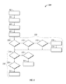
- FIG. 3 is a flowchart of a process 300 for identifying objects in proximity to a vehicle and controlling an active safety control system of the vehicle, in accordance with an exemplary embodiment.
- the process 300 will also be described further below in connection with FIGS. 4 and 5 , which depict exemplary sub-processes thereof.
- the process 300 can be used in connection with the vehicle 100 of FIGS. 1 and 6 , the ASCS 170 of FIG. 1 , and objects such as the target objects 604 of FIGS. 6 and 2 .
- References to the vehicle or host vehicle herein may pertain to the vehicle 100 of FIGS. 1 and 6 (including the ASCS 170 of FIGS.
- the process 300 is preferably performed continuously during a current drive cycle (or ignition cycle) of the vehicle.
- the process includes the step of obtaining vehicle data (step 302 ).
- vehicle data preferably includes data and related information pertaining to lateral and longitudinal positions, velocities, and accelerations of the vehicle (preferably pertaining to measurements of one or more sensors 230 , such as the wheel speed sensors 238 and/or accelerometers 240 of FIG. 2 and/or via communications provided by the communication unit 204 of FIG. 2 ), as well as measures of a driver's engagement of a brake pedal, accelerator pedal, and steering wheel of the vehicle (preferably pertaining to measurements of various sensors 230 , such as the brake pedal sensors 232 , the accelerator pedal sensors 234 , and the steering angle sensors 236 of FIG. 2 , respectively and/or via communications provided by the communication unit 204 of FIG.
- the vehicle data of step 302 is gathered throughout the drive cycle of the vehicle, preferably continuously, and provided to the processor 250 of FIG. 2 for processing.
- An object is detected in proximity to the vehicle (step 304 ).
- the object (also referred to herein as the target and/or the target object) is preferably detected by the object detection unit 202 of FIG. 2 , most preferably by one or more of the cameras 212 , radar devices 214 , and/or other devices 216 thereof.
- Information and data pertaining to the detected target object are also obtained (step 306 ).
- the target object data preferably includes data and related information pertaining to lateral and longitudinal positions, lateral and longitudinal velocities, and lateral and longitudinal accelerations of the target object. This information and data is preferably obtained via the object detection unit 202 of FIG.
- the target object data of step 306 is gathered throughout the drive cycle of the vehicle, preferably continuously.
- step 307 Various determinations and calculations are also performed (step 307 ).
- the determinations and calculations utilize the vehicle data of step 302 and the target object data of step 306 , and yield calculated results pertaining to lateral and longitudinal positions, velocities, and accelerations of the vehicle, lateral and longitudinal positions, velocities, and accelerations of the target object, and relative lateral and longitudinal positions, velocities, and accelerations between the target object and the vehicle.
- the calculations and determinations of step 307 are preferably performed by the processor 250 of FIG. 2 throughout the drive cycle of the vehicle, preferably continuously, and are utilized by the processor 250 of FIG. 2 for further processing in identifying/classifying the target object and controlling one or more active safety features, such as described below.
- the predetermined threshold comprises a value or point at which significant evasive action is needed to avoid a collision, for example a braking action exceeding 0.55 G's or a steering action exceeding 0.3 G's (with “G”, as used throughout this application, representing the acceleration of gravity, or 9.8 meters per second squared (m/s 2 ).
- the predetermined threshold is preferably stored in the memory 252 of FIG. 2 as a stored value 262 thereof. If it is determined that the time to collision is less than the predetermined threshold, the process proceeds directly to step 318 , described further below.
- a warning is provided (step 314 ).
- the warning preferably comprises an audio and/or visual warning (such as a verbal and/or audible notification of a possible imminent collision) provided by the driver notification unit 208 of FIG. 2 .
- one or more remedial actions may also be taken (step 316 ). Such remedial actions may include initiation of automatic steering actions using the steering system 150 of FIG. 1 and/or initiating automatic braking actions using the braking system 160 of FIG. 1 , based on instructions provided thereto by the processor 250 of FIG. 2 . The process then proceeds to step 318 , described further below.
- a notation may be stored in the memory 252 of FIG. 1 indicating that the target object appears to be a vehicle that was detected by a radar, a sensor, and/or another device but not by a camera, so that the target object may potentially be treated differently (for example, requiring additional redundancy checks) in the implementation of active safety functionality.
- Steps 308 - 316 provide for additional monitoring of target objects in situations in which the object detection unit 202 of FIG. 2 does not include a camera 212 , or in situations in which a camera 212 is not functioning properly and/or the target object is not readily detectible via a camera 212 (such as when a line of sight between the target object and the vehicle is blocked, for example by another vehicle and/or object).
- the algorithm of steps 308 - 316 is performed regardless of whether or not the camera detected the object.
- steps 308 - 316 are denoted as representing a first sub-process 330 of the process 300 .
- steps of the first sub-process 330 are depicted in FIG. 4 and are described directly below in connection therewith.
- the first sub-process 330 of FIG. 3 begins with a presumption that the target object is not a motor vehicle (step 402 ). Specifically, an inferred vehicle value is set to an initial value of “false”, indicating that the target object is not considered to be a motor vehicle. The inferred vehicle value maintains this value of “false” unless and until the steps described below provide a sufficient indication that the target object is a motor vehicle (or a motorized vehicle). The inferred vehicle value is preferably set by the processor 250 of FIG. 2 .
- Determinations are made as to whether all entry conditions are met that would indicate that the target object may be a motor vehicle (step 404 ). These determinations are preferably made by the processor 250 of FIG. 2 , most preferably continuously, throughout the drive cycle, based on the data and information of steps 302 - 307 of FIG. 3 .
- the first entry condition is whether an object identifier number assigned to the target object remains constant.
- the object identifier number pertains to the pseudo-random number assigned to the target object by the processor 250 of FIG. 2 during step 306 of FIG. 3 .
- the second entry condition is whether an absolute value of relative longitudinal velocity between the target object and the host vehicle is less than a predetermined threshold.
- the relative longitudinal velocity preferably comprises a difference between (i) a component of the velocity of the target object with respect to a longitudinal direction of movement of the host vehicle and (ii) a component of the longitudinal velocity of the host vehicle in the direction of movement of the host vehicle.
- This predetermined threshold is preferably stored in the memory 252 of FIG. 2 as a stored value 262 thereof. In one preferred embodiment, this predetermined threshold is equal to five meters per second (5.0 m/s).
- the relative longitudinal velocity is preferably calculated by the processor 250 of FIG. 2 during step 307 of FIG. 3 .
- the third entry condition is whether an absolute value of relative lateral velocity between the target object and the host vehicle is less than a predetermined threshold.
- This predetermined threshold is preferably stored in the memory 252 of FIG. 2 as a stored value 262 thereof. In one preferred embodiment, this predetermined threshold is equal to two meters per second (2.0 m/s).
- the relative lateral velocity is preferably calculated by the processor 250 of FIG. 2 during step 307 of FIG. 3 .
- the fourth entry condition is whether the target object is moving in the same direction as the host vehicle.
- the directions of the host vehicle and the target object used for this comparison are preferably calculated by the processor 250 of FIG. 2 during steps 302 and 306 , respectively, of FIG. 3 .
- the fifth entry condition is whether the target object is actively measured by the object detection unit. Specifically, the fifth entry condition preferably is satisfied when one or more of the devices 212 , 214 , and/or 216 of the object detection unit 202 of FIG. 2 are actively measuring the target object without interruption.
- the sixth entry condition is whether an absolute value of a lateral lane offset between the target object and the vehicle is less than a predetermined threshold.
- This predetermined threshold is preferably stored in the memory 252 of FIG. 2 as a stored value 262 thereof. In one preferred embodiment, this predetermined threshold is equal to 5.4 meters.
- the absolute value of the lateral lane offset is preferably calculated by the processor 250 of FIG. 2 during step 307 of FIG. 3 .
- the seventh entry condition is whether a velocity of the host vehicle is greater than a predetermined threshold.
- This predetermined threshold is preferably stored in the memory 252 of FIG. 2 as a stored value 262 thereof. In one preferred embodiment, this predetermined threshold is equal to 10 meters per second (10.0 m/s).
- the velocity of the host vehicle is preferably calculated or obtained by the processor 250 of FIG. 2 during step 302 of FIG. 3 .
- the eighth entry condition is whether the data and information pertaining to the target object pass one or more plausibility checks.
- the plausibility checks may include determinations as to whether changes in position, lateral offset, and velocity pertaining to the target object and/or relative to the host vehicle remain within ranges that are plausible for the target object.
- the plausibility checks are preferably performed by the processor 250 of FIG. 2 during step 307 of FIG. 3 .
- a counter for the inferred vehicle value is set (or re-set) to the “false” position (step 406 ), indicating that the target object is not a motor vehicle.
- This setting (or re-setting) of the counter is preferably made by the processor 250 of FIG. 2 .
- step 408 the above-referenced counter for the inferred vehicle value is incremented.
- the counter is preferably incremented by the processor 250 of FIG. 2 . If at any time any of the entry conditions of step 404 are no longer satisfied, the process proceeds instead to step 406 , and the counter is re-set back equal to the “false” value indicating that the target object is not a motor vehicle.
- the counter is preferably greater than the predetermined threshold when each of the entry conditions of step 404 have been satisfied, continuously, for at least a predetermined amount of time.
- the predetermined threshold for the counter of step 410 (and/or the predetermined amount of time required for the entry conditions to be satisfied in a continuous manner) is preferably stored in the memory 252 of FIG. 2 as a stored value 262 thereof. In one embodiment, this predetermined amount of time is equal to approximately three seconds. However, this may vary in other embodiments.
- step 410 If it is determined in step 410 that the counter is not yet greater than the predetermined threshold (and/or that each of the entry conditions of step 404 has not yet been satisfied continuously for at least the predetermined amount of time), then the process proceeds to step 402 , as the inferred vehicle value remains equal to “false” (indicating that the target object has not yet been determined to be a motor vehicle), but the counter is not re-set (as the determinations thus far would have indicated that the target object may be a motor vehicle). Steps 402 - 410 then repeat until a determination is made in a subsequent iteration of step 410 that the counter is greater than the predetermined threshold (and/or that each of the entry conditions of step 404 have been satisfied continuously for at least the predetermined amount of time).
- step 410 If it is determined in step 410 that the counter is greater than the predetermined threshold (and/or that each of the entry conditions of step 404 have been satisfied continuously for at least the predetermined amount of time), then the inferred vehicle value is set equal to “true” (step 412 ). Specifically, during step 412 , the target object is classified as a motor vehicle.
- Determinations are made as to whether any exit conditions are met that would indicate that the target object is not a motor vehicle (step 414 ). These determinations are preferably made by the processor 250 of FIG. 2 , preferably continuously, throughout the drive cycle, based on the data and information of steps 302 - 307 of FIG. 3 .
- the first exit condition is whether the target object (and/or data or information pertaining thereto) is no longer actively measured and/or reported to the processor 250 of FIG. 1 by the object detection unit (such as by one or more of the devices 212 , 214 , and/or 216 of the object detection unit 202 of FIG. 2 ).
- the second exit condition is whether the target object is moving in the opposite direction as the host vehicle. This determination is preferably made using the directions of the host vehicle and the target object as calculated by the processor 250 of FIG. 2 during steps 302 and 306 , respectively, of FIG. 3 .
- the third exit condition is whether any additional sensor returns are reported in close proximity to the target object. Specifically, the third exit condition is satisfied when one or more devices 212 , 214 , and/or 216 of the object detection unit 202 of FIG. 2 provide conflicting measurements, data, and/or information pertaining to the target object. By way of example, the third exit condition is satisfied if one of the devices 212 , 214 , and/or 216 of the object detection unit 202 of FIG. 2 provides an indication that the target object (the inferred vehicle) is in close proximity to another target object. This prevents the inferred vehicle status from being inadvertently transferred to another target object.
- the fourth exit condition is whether the object identifier number assigned to the target object changes. Specifically, the fourth exit condition is satisfied when a change occurs to the pseudo-random number assigned to the target object by the processor 250 of FIG. 2 during step 306 of FIG. 3 .
- the fifth exit condition is whether the absolute value of a lateral lane offset between the target object and the vehicle (preferably, as calculated by the processor 250 of FIG. 2 during step 307 of FIG. 3 ) is greater than a predetermined threshold.
- This predetermined threshold is preferably stored in the memory 252 of FIG. 2 as a stored value 262 thereof. In one preferred embodiment, this predetermined threshold is equal to 5.4 meters.
- the sixth exit condition is whether the target object fails one or more plausibility checks. Similar to those described above in connection with the entry conditions of step 404 , the plausibility checks of step 414 may include determinations as to whether changes in position, lateral offset, and velocity pertaining to the target object and/or relative to the host vehicle remain within ranges of vehicles that are plausible for the target object. The plausibility checks are preferably performed by the processor 250 of FIG. 2 during step 307 of FIG. 3 .
- step 414 If one or more of the exit conditions of step 414 are satisfied, then the process proceeds to the above-referenced step 406 , and the counter for the inferred vehicle value is set (or re-set) to the “false” position, indicating that the target object is not a motor vehicle.
- This setting (or re-setting) of the counter is preferably made by the processor 250 of FIG. 2 .
- the process then returns to step 402 for the beginning of a new iteration.
- step 414 determines whether none of the exit conditions of step 414 are satisfied. If none of the exit conditions of step 414 are satisfied, then the target object remains classified as a motor vehicle. The determinations of step 414 thereafter continue, preferably continuously, during the driving cycle so long as none of the exit conditions of step 414 are satisfied.
- this determination comprises a determination as to whether the target object comprises a pedestrian or a bicycle, and/or a similar-type device (by way of example, including a unicycle, stroller, wagon, skateboard, or the like). This determination is preferably made by the processor 250 of FIG. 2 .
- active system functionality is utilized in accordance with one or more first thresholds (steps 320 and 322 ). Specifically, a time to collision is calculated (step 320 ), preferably by the processor 250 of FIG. 2 . In addition, an active safety action is taken if the time to collision is less than a first predetermined threshold (step 322 ).
- the first predetermined threshold is preferably stored in the memory 252 of FIG. 2 as a stored value 262 thereof.
- the active safety action comprises the application of automatic braking using the braking system 160 of FIG. 1 based on instructions provided thereto by the processor 250 of FIG.
- this first predetermined time to collision threshold is equal to a point or value at which a majority of drivers would have initiated an aggressive avoidance maneuver of some kind. In one such embodiment, this predetermined threshold represents a time to collision between 0.5 to 1.5 seconds. However, this predetermined threshold may vary, and is also preferably dependent upon the speed of the host vehicle.
- active system functionality is utilized in accordance with one or more second thresholds (steps 324 and 326 ).
- a time to collision is calculated (step 324 ), preferably by the processor 250 of FIG. 2 .
- an active safety action is taken if the time to collision is less than a second predetermined threshold (step 326 ).
- the second predetermined threshold is preferably stored in the memory 252 of FIG. 2 as a stored value 262 thereof.
- the active safety action comprises the application of automatic braking using the braking system 160 of FIG.
- this second time to collision threshold is approximately between 0.7 and 1.3 seconds for the time to collision. However, this may vary in other embodiments.
- the second predetermined threshold utilized in steps 324 and 326 is greater than the first predetermined threshold utilized in steps 320 and 322 .
- the magnitude of the second deceleration of steps 324 and 326 is less than that of the first deceleration of steps 320 and 322 . Accordingly, if the target object is classified as an individual not in a motor vehicle (such as a pedestrian or an individual on a bicycle), automatic braking is applied relatively earlier, but with a relatively lesser amount of deceleration, as compared with situations in which the target object is determined to be a motor vehicle.
- steps 318 - 326 provide an earlier active safety response and an earlier warning to the driver of the host vehicle when the target object is an individual not in a motor vehicle and a collision is likely. The driver can then also have relatively more time to take his or her own safety measures as appropriate. As referenced in FIG. 3 , steps 318 - 326 are denoted as representing a second-process 340 of the process 300 .
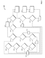
- active safety functionality is implemented in connection with an adjusted set of calibrations or active safety thresholds (preferably, including adjusted thresholds for an initiation of automatic braking and a host vehicle deceleration rate for the automatic braking) when the target object is classified as a pedestrian that is not in a motor vehicle (for example, when the target object is classified as a pedestrian, a bicycle, or a similar device).
- an adjusted set of calibrations or active safety thresholds preferably, including adjusted thresholds for an initiation of automatic braking and a host vehicle deceleration rate for the automatic braking
- This determination is preferably made by the processor 250 of FIG. 2 based on calculations made during steps 302 - 307 of FIG. 3 .
- This threshold is preferably stored in the memory 252 of FIG. 2 as one of the stored values 262 thereof. In one embodiment, this predetermined threshold is equal to approximately 20 meters. However, this may vary in other embodiments.
- step 504 If it is determined in step 502 that the range between the host vehicle and the target object is greater than or equal to the threshold of step 502 , then the adjusted set of active safety thresholds are not implemented (step 504 ).
- the standard or typical active safety thresholds are utilized, consistent with the target object being classified as a motor vehicle rather than a pedestrian, a bicycle, or the like.
- automatic braking is provided at a first magnitude, to thereby attain a first rate of deceleration for the vehicle, if the calculated time to collision between the target object and the vehicle is less than a first predetermined threshold.
- step 506 a determination is made as to whether a time to collision between the host vehicle and the target object is less than a predetermined threshold (step 506 ).
- This determination is preferably made by the processor 250 of FIG. 2 based on calculations made during steps 302 - 307 of FIG. 3 .
- This threshold is preferably stored in the memory 252 of FIG. 2 as one of the stored values 262 thereof. In one embodiment, this predetermined threshold is approximately within a range of between 0.7 and 1.3 seconds for the time to collision. However, this may vary in other embodiments.
- step 506 If it is determined in step 506 that the time to collision is greater than or equal to the predetermined threshold of step 506 , then the process proceeds to the above-referenced step 504 , in which the standard or typical active safety thresholds apply (and the adjusted set of active safety thresholds are not implemented).
- step 506 determines whether a collision is likely between the host vehicle and the target object based on their respective trajectories.
- the time to collision is multiplied (preferably by the processor 250 of FIG. 2 ) by the lateral velocities of the host vehicle and the target object to ascertain the projected lateral positions of the host vehicle and the target object. If a resulting relative lateral position of the target object with respect to the host vehicle is within a half-width of the host vehicle (for example, around 1.1 meters, for some vehicles), then a collision is considered to be likely.
- step 508 This determination is preferably made by the processor 250 of FIG. 2 based on calculations made during steps 302 - 307 of FIG. 3 . If it is determined in step 508 that a collision between the host vehicle and the target object is unlikely, then the process proceeds to the above-referenced step 504 , in which the standard or typical active safety thresholds apply (and the adjusted set of active safety thresholds are not implemented).
- step 510 a determination is made as to whether the velocity of the host vehicle is less than a predetermined threshold (step 510 ).
- This determination is preferably made by the processor 250 of FIG. 2 based on calculations made during steps 302 - 307 of FIG. 3 .
- This threshold is stored in the memory 252 of FIG. 2 as one of the stored values 262 thereof. In one embodiment, this predetermined threshold is equal to approximately ten meters per second (m/s). However, this may vary in other embodiments.
- step 510 If it is determined in step 510 that the velocity of the host vehicle is greater than or equal to the predetermined threshold of step 510 , then the process proceeds to the above-referenced step 504 , in which the standard or typical active safety thresholds apply (and the adjusted set of active safety thresholds are not implemented).
- step 512 a determination is made as to whether a position of the accelerator pedal is greater than a predetermined threshold (step 512 ).
- This determination is preferably made by the processor 250 of FIG. 2 based on calculations made during steps 302 - 307 of FIG. 3 using measurements obtained from the accelerator pedal sensors 234 of FIG. 2 .
- This threshold is stored in the memory 252 of FIG. 2 as one of the stored values 262 thereof.
- this predetermined threshold is equal to approximately twenty five percent (25%) to forty percent (40%) of full travel or engagement of the accelerator pedal. However, this may vary in other embodiments.
- a similar determination may be made with respect to a measure of movement of the accelerator pedal and/or a measure of force applied to the accelerator pedal by a driver of the vehicle, instead of or in addition to the accelerator pedal position
- step 512 If it is determined in step 512 that the position of the accelerator pedal is greater than or equal to the predetermined threshold of step 512 (and/or that the movement and/or force applied to the accelerator pedal are greater than or equal to respective predetermined thresholds), then the automatic braking triggers are suppressed (step 513 ). Specifically, in light of the determination of step 512 , which indicates that the driver is engaging the accelerator pedal of the host vehicle, automatic braking is not applied based on the current data, regardless of whether other criteria might have otherwise called for automatic braking. The automatic braking triggers are preferably suppressed by the processor 250 of FIG. 2 . Following step 513 , the process proceeds to the above-referenced step 504 , in which the standard or typical active safety thresholds apply (and the adjusted set of active safety thresholds are not implemented), subject to the suppression of step 513 .
- This determination is preferably made by the processor 250 of FIG. 2 based on calculations made during steps 302 - 307 of FIG. 3 using measurements obtained by the steering angle sensors 236 of FIG. 2 .
- This threshold is stored in the memory 252 of FIG. 2 as one of the stored values 262 thereof. In one embodiment, this predetermined threshold is equal to approximately 4 radians per second (rad/sec). However, this may vary in other embodiments.
- step 514 If it is determined in step 514 that the absolute value of a steering wheel angle gradient is greater than the predetermined threshold of step 514 , then the automatic braking triggers are suppressed (step 515 ). Specifically, in light of the determination of step 514 , which indicates that the driver is actively engaging the steering wheel of the host vehicle, automatic braking is not applied based on the current data, regardless of whether other criteria might have otherwise called for automatic braking.
- the automatic braking triggers are preferably suppressed by the processor 250 of FIG. 2 .
- step 515 the process proceeds to the above-referenced step 504 , in which the standard or typical active safety thresholds apply (and the adjusted set of active safety thresholds are not implemented), subject to the suppression of step 515 .
- step 514 if it is determined in step 514 that the absolute value of the steering wheel angle gradient is less than or equal to the predetermined threshold of step 514 , then a determination is made as to whether a lateral position of the target object relative to the host vehicle is less than a predetermined threshold (step 516 ).
- This determination is preferably made by the processor 250 of FIG. 2 based on calculations made during steps 302 - 307 of FIG. 3 .
- This threshold is stored in the memory 252 of FIG. 2 as one of the stored values 262 thereof. In one embodiment, this predetermined threshold is equal to approximately ten meters. However, this may vary in other embodiments.
- step 516 If it is determined in step 516 that the lateral position of the target object relative to the host vehicle is greater than or equal to the predetermined threshold of step 516 , then the process proceeds to the above-referenced step 504 , in which the standard or typical active safety thresholds apply (and the adjusted set of active safety thresholds are not implemented).
- This determination is preferably made by the processor 250 of FIG. 2 based on calculations made during steps 302 - 307 of FIG. 3 .
- This threshold is stored in the memory 252 of FIG. 2 as one of the stored values 262 thereof. In one embodiment, this predetermined threshold is equal to approximately 1.6 meters per second (m/s). However, this may vary in other embodiments.
- step 518 If it is determined in step 518 that the change in lateral position of the target object is less than or equal to the predetermined threshold of step 518 , then the process proceeds to the above-referenced step 504 , in which the standard or typical active safety thresholds apply (and the adjusted set of active safety thresholds are not implemented).
- step 518 determines whether the change in lateral position of the target object is greater than the predetermined threshold of step 518 . If it is determined in step 518 that the change in lateral position of the target object is greater than the predetermined threshold of step 518 , then a determination is made as to whether a count is greater than a predetermined value (step 520 ). This determination is preferably made by the processor 250 of FIG.
- this predetermined threshold is equal to approximately 120 milliseconds (ms). However, this may vary in other embodiments.
- the applicable threshold of step 520 is stored in the memory 252 of FIG. 2 as one of the stored values 262 thereof.
- step 520 If it is determined in step 520 that the count is less than or equal to the applicable threshold of step 520 , the count is incremented by one (step 522 ). The count is preferably incremented by the processor 250 of FIG. 1 . Steps 516 - 522 thereafter repeat until there is a determination in a subsequent iteration of step 520 that the count is greater than the applicable threshold of step 520 .
- the target object is classified as being an individual that is not in a motor vehicle (step 523 ).
- This classification (which also may be referenced herein as an identification and/or determination) is preferably made by the processor 250 of FIG. 2 .
- This classification preferably comprises a determination that the target object detected in step 304 of FIG. 3 comprises one or more pedestrians and/or one or more human individuals on bicycles or other similar devices.
- step 525 If it is determined that the driver is applying the brake pedal, then the automatic braking triggers are suppressed (step 525 ). Specifically, in light of the determination of step 524 that the driver is engaging the brake pedal of the host vehicle, automatic braking is not applied based on the current data, regardless of whether other criteria might have otherwise called for automatic braking.
- the automatic braking triggers are preferably suppressed by the processor 250 of FIG. 2 .
- the process proceeds to the above-referenced step 504 , in which the standard or typical active safety thresholds apply (and the adjusted set of active safety thresholds are not implemented), subject to the suppression of step 525 .
- step 526 a determination is made as to whether any other particular scenario recognition algorithms are active that might conflict with the second sub-process 340 (step 526 ).
- scenario recognition algorithms may include other specialized braking algorithms such as, by way of example, motorcycle detection algorithms, head-on target algorithms, and the like. This determination is preferably made by the processor 250 of FIG. 2 . If it is determined in step 526 that there are one or more such other particular scenario recognition algorithms that are active that might conflict with the second sub-process 340 , then the process proceeds to the above-referenced step 504 , in which the standard or typical active safety thresholds apply (and the adjusted set of active safety thresholds are not implemented).
- active safety thresholds are adjusted (step 528 ). As described in greater detail further below, in a preferred embodiment, a time to collision threshold for initiating automatic braking is increased, and a magnitude of automatic braking is decreased, in order to provide an earlier and more gradual automatic braking action and accompanying warning/notification when the target object comprises a pedestrian, a bicycle, or the like rather than a motor vehicle.
- step 530 The active safety functionality is implemented accordingly using the adjusted active safety thresholds referenced above (step 530 ).
- automatic braking is implemented via instructions provided to the braking system 160 of FIG. 1 by the processor 250 of FIG. 1 using adjusted thresholds for triggering the automatic braking and for the magnitude of the automatic braking based on the classification of the target object as an individual that is not in a vehicle.
- step 530 automatic braking is applied when a time to collision (as calculated by the processor 250 of FIG. 2 ) between the target object and the host vehicle is less than a second (or adjusted) predetermined time to collision threshold.
- This second predetermined time to collision threshold is greater than the typical (or first) time to collision threshold used when the target object is classified as a motor vehicle and not a pedestrian, a bicycle, or the like, such as in step 504 .
- step 530 automatic braking is applied with a second (or adjusted) magnitude is less than the typical (or first) magnitude of automatic braking that is provided when the target object is classified as a motor vehicle and not a pedestrian, a bicycle, or the like, such as in step 504 .
- the second magnitude of automatic braking of step 530 has a braking pressure and braking force that are less than the typical braking pressure and braking forces, respectively, of the automatic braking of step 504 .
- the second magnitude of automatic braking of step 530 (namely, when the target object is classified as a pedestrian, a bicycle, or the like) is calculated by the processor 250 of FIG.
- step 504 in order to attain a second rate of deceleration for the host vehicle, with the second rate of deceleration being less than a first rate of deceleration attained using the first magnitude of automatic braking of step 504 (namely, when the target object comprises a motor vehicle).
- the automatic braking begins relatively sooner, and with a relatively smaller deceleration of the host vehicle, when the target object is classified as an individual that is not in a motor vehicle (provided that the other criteria set forth above in connection with the second sub-process 340 are also satisfied), as compared to when the target object is classified as a motor vehicle (for example, with reference to step 504 ).
- the resulting earlier application of automatic braking provides additional braking time to help in avoiding a collision between the host vehicle and the pedestrian or bicycle.
- the automatic application of the brake system in this manner also provides an earlier warning to the driver to take any other measures (such as additional braking by the driver, steering of the host vehicle, and the like) that may further help to prevent a collision.
- one or more other audio and/or visual warnings may also be provided, such as by the driver notification unit 208 of FIG. 2 based on instructions provided by the processor 250 of FIG. 2 .
- the magnitude of automatic braking in step 532 is equal to that of the above-reference first magnitude of automatic braking of step 504 (for example, in which the target object is classified as a motor vehicle), so as to thereby increase the deceleration rate of the vehicle to be equal to that of step 504 after the predetermined amount of time. Accordingly, when the target object is classified as a pedestrian, a bicycle, or the like, the automatic braking starts relatively earlier and at a relatively lower magnitude as compared with a scenario in which the target object is classified as a motor vehicle, and subsequently increases in magnitude after the predetermined amount of time. In one embodiment, this predetermined amount of time is equal to approximately 0.5 seconds.
- the increase in magnitude of the automatic braking is provided via the braking system 160 of FIG. 1 based on instructions provided thereto by the processor 250 of FIG. 2 .
- methods, systems, and vehicles are provided for identifying objects in proximity to a host vehicle, and for controlling active safety functionality for the host vehicle based at least in part on the identifications.
- the disclosed methods, systems, and vehicles classify the objects in proximity to the vehicle as motor vehicles or individuals not in a motor vehicle based on various factors, including lateral and longitudinal position and movement of the target and the host vehicle.
- warnings, automatic braking, and automatic steering are provided and controlled based at least in part on these classifications.
- the disclosed methods, systems, and vehicles may vary from those depicted in the Figures and described herein.
- the vehicle 100 , ASCS 170 , and/or various components thereof may vary from that depicted in FIGS. 1 and 2 and described in connection therewith.
- the vehicle 100 , the target objects 604 , and/or the placement thereof may differ from that depicted in FIG. 6 .
- certain steps of the process 300 (and/or sub-processes or sub-steps thereof) may vary from those depicted in FIGS. 3-5 and/or described above in connection therewith.
Landscapes
- Engineering & Computer Science (AREA)
- Transportation (AREA)
- Mechanical Engineering (AREA)
- Automation & Control Theory (AREA)
- Chemical & Material Sciences (AREA)
- Combustion & Propulsion (AREA)
- Physics & Mathematics (AREA)
- General Physics & Mathematics (AREA)
- Traffic Control Systems (AREA)
- Control Of Driving Devices And Active Controlling Of Vehicle (AREA)
Abstract
Description
Claims (19)
Priority Applications (3)
| Application Number | Priority Date | Filing Date | Title |
|---|---|---|---|
| US13/189,415 US9511751B2 (en) | 2011-07-22 | 2011-07-22 | Object identification and active safety control for vehicles |
| DE102012210679.0A DE102012210679B4 (en) | 2011-07-22 | 2012-06-25 | Object identification and active safety control for vehicles |
| CN201210252396.XA CN102887147B (en) | 2011-07-22 | 2012-07-20 | Object identifying and active safety control for vehicle |
Applications Claiming Priority (1)
| Application Number | Priority Date | Filing Date | Title |
|---|---|---|---|
| US13/189,415 US9511751B2 (en) | 2011-07-22 | 2011-07-22 | Object identification and active safety control for vehicles |
Publications (2)
| Publication Number | Publication Date |
|---|---|
| US20130024075A1 US20130024075A1 (en) | 2013-01-24 |
| US9511751B2 true US9511751B2 (en) | 2016-12-06 |
Family
ID=47502320
Family Applications (1)
| Application Number | Title | Priority Date | Filing Date |
|---|---|---|---|
| US13/189,415 Active 2032-10-03 US9511751B2 (en) | 2011-07-22 | 2011-07-22 | Object identification and active safety control for vehicles |
Country Status (3)
| Country | Link |
|---|---|
| US (1) | US9511751B2 (en) |
| CN (1) | CN102887147B (en) |
| DE (1) | DE102012210679B4 (en) |
Cited By (4)
| Publication number | Priority date | Publication date | Assignee | Title |
|---|---|---|---|---|
| US10515553B2 (en) * | 2015-02-26 | 2019-12-24 | Volvo Truck Corporation | Method of controlling inter-vehicle gap(s) |
| US10569730B2 (en) * | 2015-03-31 | 2020-02-25 | Denso Corporation | Object detecting apparatus and object detecting method |
| US20210003695A1 (en) * | 2018-03-23 | 2021-01-07 | Soken, Inc. | Radar apparatus |
| US11623707B2 (en) | 2019-12-06 | 2023-04-11 | GEKOT Inc. | Collision alert systems and methods for micromobility vehicles |
Families Citing this family (46)
| Publication number | Priority date | Publication date | Assignee | Title |
|---|---|---|---|---|
| JP5708456B2 (en) * | 2011-11-21 | 2015-04-30 | トヨタ自動車株式会社 | Vehicle control device |
| DE102012004650A1 (en) * | 2012-03-07 | 2013-09-12 | Audi Ag | Method for testing the functionality of a driver assistance system installed in a test vehicle |
| US9495874B1 (en) * | 2012-04-13 | 2016-11-15 | Google Inc. | Automated system and method for modeling the behavior of vehicles and other agents |
| US8825371B2 (en) * | 2012-12-19 | 2014-09-02 | Toyota Motor Engineering & Manufacturing North America, Inc. | Navigation of on-road vehicle based on vertical elements |
| US9975483B1 (en) * | 2013-02-08 | 2018-05-22 | Amazon Technologies, Inc. | Driver assist using smart mobile devices |
| JP5905846B2 (en) | 2013-03-29 | 2016-04-20 | 株式会社日本自動車部品総合研究所 | Crossing determination device and program |
| JP5842863B2 (en) * | 2013-05-14 | 2016-01-13 | 株式会社デンソー | Collision mitigation device |
| DE102013211427B4 (en) | 2013-06-18 | 2016-10-13 | Continental Automotive Gmbh | Method and device for determining a driving state of an external motor vehicle |
| EP2821308B1 (en) * | 2013-07-03 | 2016-09-28 | Volvo Car Corporation | Vehicle system for control of vehicle safety parameters, a vehicle and a method for controlling safety parameters |
| DE102014202453B4 (en) * | 2014-02-11 | 2018-12-06 | Bayerische Motoren Werke Aktiengesellschaft | Methods and systems for autonomous vehicle detection, distance measurement and distance control |
| US9290186B2 (en) * | 2014-03-10 | 2016-03-22 | Ford Global Technologies, Llc | Messaging via vehicle steering wheel |
| US9507345B2 (en) * | 2014-04-10 | 2016-11-29 | Nissan North America, Inc. | Vehicle control system and method |
| US9561795B2 (en) * | 2014-05-16 | 2017-02-07 | Hyundai Motor Company | Vehicle collision avoidance apparatus and method |
| KR102209794B1 (en) * | 2014-07-16 | 2021-01-29 | 주식회사 만도 | Emergency braking system for preventing pedestrain and emergency braking conrol method of thereof |
| KR101628503B1 (en) * | 2014-10-27 | 2016-06-08 | 현대자동차주식회사 | Driver assistance apparatus and method for operating thereof |
| EP3021134B1 (en) * | 2014-11-13 | 2020-06-03 | Veoneer Sweden AB | Sensor handover |
| KR20170072935A (en) * | 2014-12-16 | 2017-06-27 | 비와이디 컴퍼니 리미티드 | Electric vehicle, active safety control system of electric vehicle, and control method therefor |
| DE102015202326A1 (en) * | 2015-02-10 | 2016-08-11 | Robert Bosch Gmbh | Method for operating a data processing unit of a driver assistance system and data processing unit |
| JP6115579B2 (en) | 2015-02-16 | 2017-04-19 | トヨタ自動車株式会社 | Collision avoidance device |
| CN105774776B (en) * | 2016-03-02 | 2019-06-07 | 厦门大学 | A kind of automobile pedestrian anticollision intelligence control system and method based on the collaboration of people's vehicle |
| CN106627531B (en) * | 2016-12-06 | 2019-11-29 | 智车优行科技(北京)有限公司 | For the control method of vehicle automatic emergency brake, device and vehicle |
| US11180143B2 (en) * | 2016-12-07 | 2021-11-23 | Honda Motor Co., Ltd. | Vehicle control device |
| KR102452682B1 (en) * | 2016-12-14 | 2022-10-11 | 현대자동차주식회사 | Method for Improving Avoidance Front Collision Based on Integration Control and Vehicle thereof |
| US10403145B2 (en) * | 2017-01-19 | 2019-09-03 | Ford Global Technologies, Llc | Collison mitigation and avoidance |
| US10029683B1 (en) | 2017-01-25 | 2018-07-24 | Harley-Davidson Motor Company Group, LLC | Saddle-ride vehicle with autonomous braking and method of operating same |
| US10053088B1 (en) * | 2017-02-21 | 2018-08-21 | Zoox, Inc. | Occupant aware braking system |
| US10737618B2 (en) * | 2017-04-10 | 2020-08-11 | Advanced Semiconductor Engineering, Inc. | Device and method for identifying relative position between objects |
| US10703361B2 (en) * | 2017-06-14 | 2020-07-07 | Toyota Motor Engineering & Manufacturing North America, Inc. | Vehicle collision mitigation |
| CN107757582A (en) * | 2017-09-25 | 2018-03-06 | 南京律智诚专利技术开发有限公司 | A kind of method of work of vehicle automatic running system suitable for sleety weather |
| US10671079B2 (en) | 2017-10-24 | 2020-06-02 | Waymo Llc | Speed-dependent required lateral clearance for autonomous vehicle path planning |
| KR102383436B1 (en) * | 2017-12-01 | 2022-04-07 | 현대자동차주식회사 | Platooning control apparatus and method |
| CN109969173B (en) * | 2017-12-28 | 2021-03-26 | 宝沃汽车(中国)有限公司 | Traffic device identification method and device and automobile |
| US10720070B2 (en) * | 2018-01-03 | 2020-07-21 | Qualcomm Incorporated | Adjustable object avoidance proximity threshold of a robotic vehicle based on presence of detected payload(s) |
| DE102018004303B3 (en) * | 2018-05-30 | 2019-11-21 | Daimler Ag | Method for controlling the movement of a vehicle and device for carrying out the method |
| CN109544993A (en) * | 2019-01-08 | 2019-03-29 | 吉林大学 | A kind of intelligent vehicle right-hand bend anticollision three-level early warning system and method for early warning |
| CN109703539B (en) * | 2019-02-19 | 2020-05-15 | 吉林大学 | Right-turning intelligent vehicle two-stage braking active collision avoidance system and method based on collision time |
| CN109878513A (en) | 2019-03-13 | 2019-06-14 | 百度在线网络技术(北京)有限公司 | Defensive driving strategy generation method, device, equipment and storage medium |
| JP7237428B2 (en) * | 2019-06-10 | 2023-03-13 | ダイハツ工業株式会社 | Collision avoidance support device |
| KR102706256B1 (en) * | 2019-07-08 | 2024-09-12 | 현대자동차주식회사 | Method and system for calibrating road surface information detected electronic control suspension |
| DE102020204078A1 (en) * | 2019-11-27 | 2021-05-27 | Robert Bosch Gesellschaft mit beschränkter Haftung | Driver assistance system for motor vehicles |
| US11827237B2 (en) * | 2019-12-27 | 2023-11-28 | Toyota Connected North America, Inc. | Systems and methods for real-time crash detection using telematics data |
| CN111626334B (en) * | 2020-04-28 | 2023-07-14 | 东风汽车集团有限公司 | A key control target selection method for a vehicle-mounted advanced driver assistance system |
| US11698639B2 (en) | 2020-06-04 | 2023-07-11 | Waymo Llc | Predicting jaywalking behaviors of vulnerable road users |
| CN112540365B (en) * | 2020-12-10 | 2022-07-12 | 中国第一汽车股份有限公司 | Evaluation method, device, equipment and storage medium |
| CN112606805B (en) * | 2020-12-17 | 2021-12-14 | 东风汽车集团有限公司 | Control method of automatic emergency braking system AEB of vehicle |
| US20220386091A1 (en) * | 2021-05-27 | 2022-12-01 | Lear Corporation | Motorcycle monitoring system |
Citations (20)
| Publication number | Priority date | Publication date | Assignee | Title |
|---|---|---|---|---|
| US4757450A (en) * | 1985-06-03 | 1988-07-12 | Nissan Motor Company, Limited | Method and system for automatically detecting a preceding vehicle |
| US5631639A (en) * | 1994-04-20 | 1997-05-20 | Nippondenso Co., Ltd. | Collision alarm system for automotive vehicle |
| US5642093A (en) * | 1995-01-27 | 1997-06-24 | Fuji Jukogyo Kabushiki Kaisha | Warning system for vehicle |
| US5659304A (en) * | 1995-03-01 | 1997-08-19 | Eaton Corporation | System and method for collision warning based on dynamic deceleration capability using predicted road load |
| US6018308A (en) * | 1997-07-23 | 2000-01-25 | Denso Corporation | Obstacle recognition system for automotive vehicle |
| US6085151A (en) * | 1998-01-20 | 2000-07-04 | Automotive Systems Laboratory, Inc. | Predictive collision sensing system |
| US6256584B1 (en) * | 1998-08-25 | 2001-07-03 | Honda Giken Kogyo Kabushiki Kaisha | Travel safety system for vehicle |
| US6348877B1 (en) * | 1999-06-17 | 2002-02-19 | International Business Machines Corporation | Method and system for alerting a pilot to the location of other aircraft |
| US20020091479A1 (en) * | 2001-01-09 | 2002-07-11 | Nissan Motor Co., Ltd. | Braking control system with object detection system interaction |
| US20030016161A1 (en) * | 2001-07-18 | 2003-01-23 | Hitachi, Ltd. | Vehicle control apparatus |
| US20030030552A1 (en) * | 1994-07-15 | 2003-02-13 | Tonkin Mark Christopher | Safety system for vehicles |
| US6571165B2 (en) * | 2000-08-17 | 2003-05-27 | Nissan Motor Co., Ltd. | Method and system for controlling stand-by braking torque applied to automotive vehicle |
| US6650984B1 (en) * | 2002-07-23 | 2003-11-18 | Ford Global Technologies, Llc | Method for determining a time to impact in a danger zone for a vehicle having a pre-crash sensing system |
| US20040000991A1 (en) | 2002-07-01 | 2004-01-01 | Schiffmann Jan K. | Object detection system and method of estimating object size |
| US6687577B2 (en) * | 2001-12-19 | 2004-02-03 | Ford Global Technologies, Llc | Simple classification scheme for vehicle/pole/pedestrian detection |
| US6753804B2 (en) * | 2002-05-21 | 2004-06-22 | Visteon Global Technologies, Inc. | Target vehicle identification based on the theoretical relationship between the azimuth angle and relative velocity |
| US20060089802A1 (en) * | 2004-10-26 | 2006-04-27 | Honda Motor Co., Ltd. | Vehicular control object determination system |
| US20060184297A1 (en) * | 2004-12-23 | 2006-08-17 | Higgins-Luthman Michael J | Object detection system for vehicle |
| US20090192710A1 (en) * | 2008-01-29 | 2009-07-30 | Ford Global Technologies, Llc | Method and system for collision course prediction and collision avoidance and mitigation |
| US7636625B2 (en) * | 2003-05-28 | 2009-12-22 | Robert Bosch Gmbh | Device for classifying at least one object with the aid of an environmental sensor system |
Family Cites Families (4)
| Publication number | Priority date | Publication date | Assignee | Title |
|---|---|---|---|---|
| DE10336638A1 (en) | 2003-07-25 | 2005-02-10 | Robert Bosch Gmbh | Apparatus for classifying at least one object in a vehicle environment |
| DE10334699A1 (en) | 2003-07-30 | 2005-02-17 | Robert Bosch Gmbh | Device for actuating an actuator to protect a pedestrian |
| DE10335601B4 (en) | 2003-08-04 | 2016-01-14 | Robert Bosch Gmbh | Object classification method using a 3D model database |
| DE102008023380A1 (en) | 2008-05-13 | 2009-11-19 | GM Global Technology Operations, Inc., Detroit | Motor vehicle with a driver assistance system |
-
2011
- 2011-07-22 US US13/189,415 patent/US9511751B2/en active Active
-
2012
- 2012-06-25 DE DE102012210679.0A patent/DE102012210679B4/en active Active
- 2012-07-20 CN CN201210252396.XA patent/CN102887147B/en active Active
Patent Citations (23)
| Publication number | Priority date | Publication date | Assignee | Title |
|---|---|---|---|---|
| US4757450A (en) * | 1985-06-03 | 1988-07-12 | Nissan Motor Company, Limited | Method and system for automatically detecting a preceding vehicle |
| US5631639A (en) * | 1994-04-20 | 1997-05-20 | Nippondenso Co., Ltd. | Collision alarm system for automotive vehicle |
| US20030030552A1 (en) * | 1994-07-15 | 2003-02-13 | Tonkin Mark Christopher | Safety system for vehicles |
| US5642093A (en) * | 1995-01-27 | 1997-06-24 | Fuji Jukogyo Kabushiki Kaisha | Warning system for vehicle |
| US5659304A (en) * | 1995-03-01 | 1997-08-19 | Eaton Corporation | System and method for collision warning based on dynamic deceleration capability using predicted road load |
| US6018308A (en) * | 1997-07-23 | 2000-01-25 | Denso Corporation | Obstacle recognition system for automotive vehicle |
| US6085151A (en) * | 1998-01-20 | 2000-07-04 | Automotive Systems Laboratory, Inc. | Predictive collision sensing system |
| US6256584B1 (en) * | 1998-08-25 | 2001-07-03 | Honda Giken Kogyo Kabushiki Kaisha | Travel safety system for vehicle |
| US6348877B1 (en) * | 1999-06-17 | 2002-02-19 | International Business Machines Corporation | Method and system for alerting a pilot to the location of other aircraft |
| US6571165B2 (en) * | 2000-08-17 | 2003-05-27 | Nissan Motor Co., Ltd. | Method and system for controlling stand-by braking torque applied to automotive vehicle |
| US20020091479A1 (en) * | 2001-01-09 | 2002-07-11 | Nissan Motor Co., Ltd. | Braking control system with object detection system interaction |
| US20030016161A1 (en) * | 2001-07-18 | 2003-01-23 | Hitachi, Ltd. | Vehicle control apparatus |
| US6687577B2 (en) * | 2001-12-19 | 2004-02-03 | Ford Global Technologies, Llc | Simple classification scheme for vehicle/pole/pedestrian detection |
| US6753804B2 (en) * | 2002-05-21 | 2004-06-22 | Visteon Global Technologies, Inc. | Target vehicle identification based on the theoretical relationship between the azimuth angle and relative velocity |
| US20040000991A1 (en) | 2002-07-01 | 2004-01-01 | Schiffmann Jan K. | Object detection system and method of estimating object size |
| US6794987B2 (en) * | 2002-07-01 | 2004-09-21 | Delphi Technologies, Inc. | Object detection system and method of estimating object size |
| US6650984B1 (en) * | 2002-07-23 | 2003-11-18 | Ford Global Technologies, Llc | Method for determining a time to impact in a danger zone for a vehicle having a pre-crash sensing system |
| US7636625B2 (en) * | 2003-05-28 | 2009-12-22 | Robert Bosch Gmbh | Device for classifying at least one object with the aid of an environmental sensor system |
| US20060089802A1 (en) * | 2004-10-26 | 2006-04-27 | Honda Motor Co., Ltd. | Vehicular control object determination system |
| US20060184297A1 (en) * | 2004-12-23 | 2006-08-17 | Higgins-Luthman Michael J | Object detection system for vehicle |
| US7720580B2 (en) * | 2004-12-23 | 2010-05-18 | Donnelly Corporation | Object detection system for vehicle |
| US20090192710A1 (en) * | 2008-01-29 | 2009-07-30 | Ford Global Technologies, Llc | Method and system for collision course prediction and collision avoidance and mitigation |
| CN101497330A (en) | 2008-01-29 | 2009-08-05 | 福特全球技术公司 | A system for collision course prediction |
Non-Patent Citations (1)
| Title |
|---|
| State Intellectual Property Office of the Peoples' Republic of China, Office Action in Chinese Patent Application No. 201210252396.X, mailed Oct. 30, 2014. |
Cited By (7)
| Publication number | Priority date | Publication date | Assignee | Title |
|---|---|---|---|---|
| US10515553B2 (en) * | 2015-02-26 | 2019-12-24 | Volvo Truck Corporation | Method of controlling inter-vehicle gap(s) |
| US10569730B2 (en) * | 2015-03-31 | 2020-02-25 | Denso Corporation | Object detecting apparatus and object detecting method |
| US20210003695A1 (en) * | 2018-03-23 | 2021-01-07 | Soken, Inc. | Radar apparatus |
| US11709246B2 (en) * | 2018-03-23 | 2023-07-25 | Soken, Inc. | Radar apparatus |
| US11623707B2 (en) | 2019-12-06 | 2023-04-11 | GEKOT Inc. | Collision alert systems and methods for micromobility vehicles |
| US11878761B2 (en) | 2019-12-06 | 2024-01-23 | Gekot, Inc. | Collision alert systems and methods for micromobility vehicles |
| US12351266B2 (en) | 2019-12-06 | 2025-07-08 | GEKOT Inc. | Collision alert systems and methods for micromobility vehicles |
Also Published As
| Publication number | Publication date |
|---|---|
| US20130024075A1 (en) | 2013-01-24 |
| CN102887147A (en) | 2013-01-23 |
| DE102012210679B4 (en) | 2024-02-15 |
| CN102887147B (en) | 2016-09-14 |
| DE102012210679A1 (en) | 2013-01-24 |
Similar Documents
| Publication | Publication Date | Title |
|---|---|---|
| US9511751B2 (en) | Object identification and active safety control for vehicles | |
| US8731742B2 (en) | Target vehicle movement classification | |
| US9014915B2 (en) | Active safety control for vehicles | |
| CN106564494B (en) | For controlling the method and system of the vehicle with automated driving system | |
| CN101612938B (en) | Judgment line calculation for vehicle safety system | |
| US10077050B2 (en) | Automated driving system for evaluating lane cut-out and method of using the same | |
| US20170021830A1 (en) | Adaptive cruise control profiles | |
| US20140136044A1 (en) | Active safety system and method for operating the same | |
| CN106585631B (en) | Vehicle collision system and method of using same | |
| US20170088165A1 (en) | Driver monitoring | |
| CN111127920A (en) | Method and system for early warning and control of rear-end collision prevention based on in-vehicle communication | |
| CN113859258A (en) | Method and apparatus for controlling automatic driving | |
| US20150102955A1 (en) | Measurement association in vehicles | |
| CN108437923B (en) | Pedestrian protection system and method | |
| CN111645676B (en) | Vehicle avoidance method, device, equipment and automobile | |
| US20150066307A1 (en) | Mitigation of vehicle shallow impact collisions | |
| CN107161144A (en) | Vehicle collision system and its application method | |
| US20220281451A1 (en) | Target vehicle state identification for automated driving adaptation in vehicles control | |
| US12043272B2 (en) | Radar and camera fusion based wireless communication misbehavior detection | |
| US12049234B2 (en) | Driving assistance system, driving assistance method, and storage medium | |
| Zhang et al. | AEBs perception stability study of intelligent vehicles based on C-NCAP | |
| US20240096143A1 (en) | Information processing device, vehicle, and information processing method | |
| CN106240564B (en) | Vehicle wheel component for vehicular events is adjusted | |
| CN119858599A (en) | Vehicle in-situ steering method and system with four-wheel-side motor and vehicle | |
| CN120003520A (en) | Method and system for threat detection in a vehicle |
Legal Events
| Date | Code | Title | Description |
|---|---|---|---|
| AS | Assignment |
Owner name: GM GLOBAL TECHNOLOGY OPERATIONS LLC, MICHIGAN Free format text: ASSIGNMENT OF ASSIGNORS INTEREST;ASSIGNORS:ZAGORSKI, CHAD T.;CONRAD, KEVIN P.;GANDHI, DANIEL;REEL/FRAME:026638/0200 Effective date: 20110720 |
|
| AS | Assignment |
Owner name: WILMINGTON TRUST COMPANY, DELAWARE Free format text: SECURITY AGREEMENT;ASSIGNOR:GM GLOBAL TECHNOLOGY OPERATIONS LLC;REEL/FRAME:028466/0870 Effective date: 20101027 |
|
| AS | Assignment |
Owner name: GM GLOBAL TECHNOLOGY OPERATIONS LLC, MICHIGAN Free format text: RELEASE BY SECURED PARTY;ASSIGNOR:WILMINGTON TRUST COMPANY;REEL/FRAME:034186/0776 Effective date: 20141017 |
|
| FEPP | Fee payment procedure |
Free format text: PAYOR NUMBER ASSIGNED (ORIGINAL EVENT CODE: ASPN); ENTITY STATUS OF PATENT OWNER: LARGE ENTITY |
|
| STCF | Information on status: patent grant |
Free format text: PATENTED CASE |
|
| MAFP | Maintenance fee payment |
Free format text: PAYMENT OF MAINTENANCE FEE, 4TH YEAR, LARGE ENTITY (ORIGINAL EVENT CODE: M1551); ENTITY STATUS OF PATENT OWNER: LARGE ENTITY Year of fee payment: 4 |
|
| MAFP | Maintenance fee payment |
Free format text: PAYMENT OF MAINTENANCE FEE, 8TH YEAR, LARGE ENTITY (ORIGINAL EVENT CODE: M1552); ENTITY STATUS OF PATENT OWNER: LARGE ENTITY Year of fee payment: 8 |