US950956A - Signal. - Google Patents
Signal. Download PDFInfo
- Publication number
- US950956A US950956A US49218709A US1909492187A US950956A US 950956 A US950956 A US 950956A US 49218709 A US49218709 A US 49218709A US 1909492187 A US1909492187 A US 1909492187A US 950956 A US950956 A US 950956A
- Authority
- US
- United States
- Prior art keywords
- barrel
- base
- shell
- fuse
- signal
- Prior art date
- Legal status (The legal status is an assumption and is not a legal conclusion. Google has not performed a legal analysis and makes no representation as to the accuracy of the status listed.)
- Expired - Lifetime
Links
- 238000010276 construction Methods 0.000 description 3
- 239000002360 explosive Substances 0.000 description 3
- 238000010304 firing Methods 0.000 description 3
- 244000302697 Phragmites karka Species 0.000 description 2
- ATJFFYVFTNAWJD-UHFFFAOYSA-N Tin Chemical compound [Sn] ATJFFYVFTNAWJD-UHFFFAOYSA-N 0.000 description 1
- 238000005192 partition Methods 0.000 description 1
- 230000011664 signaling Effects 0.000 description 1
Images
Classifications
-
- F—MECHANICAL ENGINEERING; LIGHTING; HEATING; WEAPONS; BLASTING
- F42—AMMUNITION; BLASTING
- F42B—EXPLOSIVE CHARGES, e.g. FOR BLASTING, FIREWORKS, AMMUNITION
- F42B4/00—Fireworks, i.e. pyrotechnic devices for amusement, display, illumination or signal purposes
- F42B4/02—Fireworks, i.e. pyrotechnic devices for amusement, display, illumination or signal purposes in cartridge form, i.e. shell, propellant and primer
Definitions
- This invention relates to improvements in signaling devices.
- the object of the invention is to provide means for holding and protecting a signal in the form of a shell or aerial projectile adapted to be discharged to a great height and to burst in the -air making a loud report and a brilliant pyrotechnical display, at night and a black cloud in day light.
- a further object isto provideelectrically operated means for igniting the fuse of the shell or rojectile in the barrel or casing from which Vit is discharged 1whereby the shell may be tired from a distant point.
- the invention consists of certain novel features of construction, combination and arran ement of parts, as will be more fully descri ed and particularly pointed out in the ap ended claims.
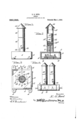
- Figure l is a side view of a signal constructed in accordance with the invention
- Fig. 2 is a vertical sectional view of the same
- Fig. 3 is a" horizontal sectional View through the base of the signal
- Fig. 4 is a side view of a modified form of the device.
- I provide a hollow base 1, one side of which is provided with an opening 2, which is normally closed by a sultable cover plate 3.
- On the opposite ends of the base Y are formed apertured fastening lugsiby means of which the base is secured toa suitable support.
- On the upper side of the base is formed a barrel attaching boss 5 having oppositely projecting barrel attaching studs 6.
- oss 5 ' is provided with a centrally disposed fuse holding passage 7.
- a fuse holdin block 8 on which are secured and spaced apart the binding posts 9 of an electric circuit.
- the binding osts 9- are connected within the base by a use 10 and tothe binding posts are secured the opposite ends of electric conducting wires 11 which may eX- tend to any point of operation and have connected thereto a switch whereby an electric circuit may be completed through said conducting wires and the fuse l0 burned out(
- a shell or rocket projecting barrel 12 Secured to the boss 5 on the base, is a shell or rocket projecting barrel 12 in the lower end of which is formed bayonet slots 13 which are adapted to be engaged with the laterally projectlng studs 6 whereby the tube 12 is detachably secured to the boss 5 on the base, thereby holding said tube or barrel in operative position.
- a detachable capor cover 14 On the end of the tube or barrel 12 is arranged a detachable capor cover 14, which is preferably conical 1n shape and has its lower edges proj ecting over the sides of the barrel, thus preventing the entrance of moisture in the upper end of the same.
- the cap 14 is detachably secured in the upper end of the barrel 12 by means of spring attaching tin ers 15 which are secured to the inner si e of the cap and project into the barrel and into engagement with the inner walls thereof thereby holding the cap into frictional engagement with the inner side of the barrel.
- the ⁇ shell or projectile 16 is arranged in the barrel and with the shell or rojectile is connected a fuse 17 connected with the propelling charge in the lower en d of the shell, said charge being separated from the explosive charge by a partition 16 and a time fuse. 12 connects the fuse 17 with the explosive charge as is clearly shown in Fig. 2, which projects Patented Mar. 1, 1910.
- Fig. 4 a modified form of the device, wherein two of the shell projecting barrels are employed, each of whlch is connected with an independent base having an independent firing mechanism. It will thus be seen that while the device has been particularly shown and described .in single form,
- a shell projecting barrel In a signal of the character described, a shell projecting barrel, a hollow base, means to secure said shell to the base, a protecting cap arranged on the upper end of the barrel, an electric fuse arranged in the base, an elecother purposes lin' said base and electric fuse will ignite 13.
- a shell projecting barrel In a signal of the character described, a shell projecting barrel, a hollow base, means to secure said shell to the base, a protecting cap arranged on the upper end of the barrel, an electric fuse arranged in the base, an elecother purposes lin' said base and electric fuse will ignite 13.
- hollow base having formed'thereon a ,boss, laterally projecting studs on said boss, a shell projecting barrel havin in its lower endbayonet slots adapted to 'lie operatively engaged' with said studs to'detachably secure said barrel to the base, binding posts arranged in said hollow base, electric conducting ⁇ wires having their terminals connected in said binding osts, an electric fuse arranged between said) posts, a shell arranged in said barrel, a firing fuse to connect said shell with the ⁇ electric fuse in the base, whereby said rin fuse is'ignited by the burning out of the ectric fuse and the projectile thereby fired from the barrel.
Landscapes
- Engineering & Computer Science (AREA)
- General Engineering & Computer Science (AREA)
- Portable Nailing Machines And Staplers (AREA)
Description
E. G. REED.
SIGNAL.
APPLICATION I'ILBD APB. ze. 190e.
Patented Mar. 1, 1910.
WW1/www EDWIN G. REED, 0E WILKINSEURG, PENNSYLVANIA.
y SIGNAL. v
Speciiication of Letters Patent.
Application filed April 26, 1909. l Serial No. 492,187.
To all 'whom 'it may concern):
Be it known that I, EDWIN G. REED, a
citizen of the United States, residing at Wilkinsburg, in the county of Allegheny and State of Pennsylvania, have invented certain new and usefulImprovements in Signals; and I do declare 'the following to be a full, clear, and exact description of the invention, such as will enable others skilled in the art to which it appertains to make and use the same.
This invention relates to improvements in signaling devices.
The object of the invention is to provide means for holding and protecting a signal in the form of a shell or aerial projectile adapted to be discharged to a great height and to burst in the -air making a loud report and a brilliant pyrotechnical display, at night and a black cloud in day light.
A further object isto provideelectrically operated means for igniting the fuse of the shell or rojectile in the barrel or casing from which Vit is discharged 1whereby the shell may be tired from a distant point.
With the foregoing and other objects in view, the invention consists of certain novel features of construction, combination and arran ement of parts, as will be more fully descri ed and particularly pointed out in the ap ended claims.
' n the accompanying drawings, Figure l is a side view of a signal constructed in accordance with the invention; Fig. 2 is a vertical sectional view of the same; Fig. 3 is a" horizontal sectional View through the base of the signal; Fig. 4 is a side view of a modified form of the device.
In the embodiment of the invention, I provide a hollow base 1, one side of which is provided with an opening 2, which is normally closed by a sultable cover plate 3. On the opposite ends of the base Y are formed apertured fastening lugsiby means of which the base is secured toa suitable support. On the upper side of the base is formed a barrel attaching boss 5 having oppositely projecting barrel attaching studs 6. The
oss 5 'is provided with a centrally disposed fuse holding passage 7.
In the base 1 is arranged a fuse holdin block 8, on which are secured and spaced apart the binding posts 9 of an electric circuit. The binding osts 9- are connected within the base by a use 10 and tothe binding posts are secured the opposite ends of electric conducting wires 11 which may eX- tend to any point of operation and have connected thereto a switch whereby an electric circuit may be completed through said conducting wires and the fuse l0 burned out( Secured to the boss 5 on the base, is a shell or rocket projecting barrel 12 in the lower end of which is formed bayonet slots 13 which are adapted to be engaged with the laterally projectlng studs 6 whereby the tube 12 is detachably secured to the boss 5 on the base, thereby holding said tube or barrel in operative position. On the end of the tube or barrel 12 is arranged a detachable capor cover 14, which is preferably conical 1n shape and has its lower edges proj ecting over the sides of the barrel, thus preventing the entrance of moisture in the upper end of the same. l
The cap 14 is detachably secured in the upper end of the barrel 12 by means of spring attaching tin ers 15 which are secured to the inner si e of the cap and project into the barrel and into engagement with the inner walls thereof thereby holding the cap into frictional engagement with the inner side of the barrel.
In the use of the device, the` shell or projectile 16 is arranged in the barrel and with the shell or rojectile is connected a fuse 17 connected with the propelling charge in the lower en d of the shell, said charge being separated from the explosive charge by a partition 16 and a time fuse. 12 connects the fuse 17 with the explosive charge as is clearly shown in Fig. 2, which projects Patented Mar. 1, 1910.
through the passage 7 and into the hollow base and is engaged withv the fuse 10 of the electric circuit whereby when said circuit fuse is burned out, the projectile fuse will be ignited and will thereby ignite the shell or projectile and cause the same to be thrown or projected from the barrel. The shell when thus fired from -the barrel will be projected into the air and will explode after reaching a certain height, thus causing a pyrotechnical display by night or a. black cloud by day, accompanied by a loud report, thus serving both as a day and night signal.
In Fig. 4 is shown a modified form of the device, wherein two of the shell projecting barrels are employed, each of whlch is connected with an independent base having an independent firing mechanism. It will thus be seen that while the device has been particularly shown and described .in single form,
a police signal, it is obvious that the same cure said barrel to the base,
" From the connection with the accompanying draw' may be employed for many in which a si al is used.
oregoing description, taken in ings, lthe construction and operation of the invention will be readily understood without re uiring a moreextended explanation.
arious changes in the form, proportion and the minor details o'f construction may be resorted to without departing from the principle or sacrificing any of the ladvantages of the invention, as defined 1n the appended claims. 1
Havingl thus described my invention, what I claim is:` l i 1. In a signal of the character described, a shell projecting barrel, a base, means to sean electrically controlled means in said bafse `forring the shell in said barrel.
2. In a signal of the character described, a shell projecting barrel, a hollow base, means to secure said shell to the base, a protecting cap arranged on the upper end of the barrel, an electric fuse arranged in the base, an elecother purposes lin' said base and electric fuse will ignite 13. In asignal of the character described, a
hollow base having formed'thereon a ,boss, laterally projecting studs on said boss, a shell projecting barrel havin in its lower endbayonet slots adapted to 'lie operatively engaged' with said studs to'detachably secure said barrel to the base, binding posts arranged in said hollow base, electric conducting` wires having their terminals connected in said binding osts, an electric fuse arranged between said) posts, a shell arranged in said barrel, a firing fuse to connect said shell with the`electric fuse in the base, whereby said rin fuse is'ignited by the burning out of the ectric fuse and the projectile thereby fired from the barrel.
4. In a signal of the characterdescribed, a
hollow supportin base, means to attach said v base to a suitab e support, a firingl barrel arrangedon said base to receive an explosive shell, an electric firing mechanism arran ed connected with said shel a cap arranged on the outer end of said bai-rel, and spring fingers to detachably -secure the ca in the outer end of the barrel'.
n testimony whereof I have hereunto set my hand in `presence of two subscribing witnesses. EDWIN G. REED. Witnesses: i' WILLIAM F. SHRoYER,
G. W. OUVER.
Priority Applications (1)
| Application Number | Priority Date | Filing Date | Title |
|---|---|---|---|
| US49218709A US950956A (en) | 1909-04-26 | 1909-04-26 | Signal. |
Applications Claiming Priority (1)
| Application Number | Priority Date | Filing Date | Title |
|---|---|---|---|
| US49218709A US950956A (en) | 1909-04-26 | 1909-04-26 | Signal. |
Publications (1)
| Publication Number | Publication Date |
|---|---|
| US950956A true US950956A (en) | 1910-03-01 |
Family
ID=3019368
Family Applications (1)
| Application Number | Title | Priority Date | Filing Date |
|---|---|---|---|
| US49218709A Expired - Lifetime US950956A (en) | 1909-04-26 | 1909-04-26 | Signal. |
Country Status (1)
| Country | Link |
|---|---|
| US (1) | US950956A (en) |
Cited By (3)
| Publication number | Priority date | Publication date | Assignee | Title |
|---|---|---|---|---|
| US2761128A (en) * | 1954-08-12 | 1956-08-28 | Wilbur B Webb | Discharge device |
| US2789467A (en) * | 1952-05-22 | 1957-04-23 | Rosenthal Henry | Smoke projectile with delay fuse |
| US4535988A (en) * | 1982-08-26 | 1985-08-20 | Foley Norman G | Football goal post with explosive-type souvenir projector |
-
1909
- 1909-04-26 US US49218709A patent/US950956A/en not_active Expired - Lifetime
Cited By (3)
| Publication number | Priority date | Publication date | Assignee | Title |
|---|---|---|---|---|
| US2789467A (en) * | 1952-05-22 | 1957-04-23 | Rosenthal Henry | Smoke projectile with delay fuse |
| US2761128A (en) * | 1954-08-12 | 1956-08-28 | Wilbur B Webb | Discharge device |
| US4535988A (en) * | 1982-08-26 | 1985-08-20 | Foley Norman G | Football goal post with explosive-type souvenir projector |
Similar Documents
| Publication | Publication Date | Title |
|---|---|---|
| US2103936A (en) | Multiple effect pyrotechnic | |
| US3049080A (en) | Rockets and rocket-borne distress signals | |
| US3712224A (en) | Decoy flare with traveling ignition charge | |
| GB1594401A (en) | Multiple payload cartridge | |
| PT86970B (en) | PROJECTIL FUMIGENO AND MUNICAO SO EQUIPADA | |
| US4392432A (en) | Air burst munitions simulator | |
| US1299217A (en) | Rocket. | |
| US4436034A (en) | Smoke grenade with successive slow and fast burning charges | |
| US4040354A (en) | Gravity-deployed double-ended anti-tank mine | |
| US2961962A (en) | Trip-wire flare | |
| US1241095A (en) | Aerial multiple explosive bomb. | |
| US809029A (en) | Signal. | |
| SE7407587L (en) | ||
| US1181190A (en) | Projectile. | |
| US4617866A (en) | Pyrotechnic or explosive device | |
| US2821922A (en) | Rocket toy and launcher therefor | |
| US1823378A (en) | Rocket | |
| US1972478A (en) | Dual salute | |
| US1785770A (en) | Aerial toy | |
| US3596599A (en) | Pyrotechnic assembly | |
| US120963A (en) | Improvement in modes of exploding torpedoes | |
| US1305187A (en) | bergman | |
| US6463856B1 (en) | Electronically and mechanically-operated ignition delay for cartridge-type pyrotechnic decoy flare ammunition | |
| US606043A (en) | Frederick bossert | |
| US1272759A (en) | Hand-grenade. |