US9507136B2 - Mode-switchable illumination system for a microscope - Google Patents
Mode-switchable illumination system for a microscope Download PDFInfo
- Publication number
- US9507136B2 US9507136B2 US14/356,410 US201214356410A US9507136B2 US 9507136 B2 US9507136 B2 US 9507136B2 US 201214356410 A US201214356410 A US 201214356410A US 9507136 B2 US9507136 B2 US 9507136B2
- Authority
- US
- United States
- Prior art keywords
- mirror
- light
- illumination
- path
- exit
- Prior art date
- Legal status (The legal status is an assumption and is not a legal conclusion. Google has not performed a legal analysis and makes no representation as to the accuracy of the status listed.)
- Expired - Fee Related
Links
- 0 *C1CC=CC1 Chemical compound *C1CC=CC1 0.000 description 1
- XYABVWSVNLIGPH-UHFFFAOYSA-N CCC1C(CC2)C(C)(C3)C3C3(CC(C)CCC3)C2C1 Chemical compound CCC1C(CC2)C(C)(C3)C3C3(CC(C)CCC3)C2C1 XYABVWSVNLIGPH-UHFFFAOYSA-N 0.000 description 1
Images


Classifications
-
- G—PHYSICS
- G02—OPTICS
- G02B—OPTICAL ELEMENTS, SYSTEMS OR APPARATUS
- G02B21/00—Microscopes
- G02B21/06—Means for illuminating specimens
-
- G—PHYSICS
- G01—MEASURING; TESTING
- G01N—INVESTIGATING OR ANALYSING MATERIALS BY DETERMINING THEIR CHEMICAL OR PHYSICAL PROPERTIES
- G01N21/00—Investigating or analysing materials by the use of optical means, i.e. using sub-millimetre waves, infrared, visible or ultraviolet light
- G01N21/62—Systems in which the material investigated is excited whereby it emits light or causes a change in wavelength of the incident light
- G01N21/63—Systems in which the material investigated is excited whereby it emits light or causes a change in wavelength of the incident light optically excited
- G01N21/64—Fluorescence; Phosphorescence
- G01N21/645—Specially adapted constructive features of fluorimeters
-
- G—PHYSICS
- G02—OPTICS
- G02B—OPTICAL ELEMENTS, SYSTEMS OR APPARATUS
- G02B17/00—Systems with reflecting surfaces, with or without refracting elements
- G02B17/02—Catoptric systems, e.g. image erecting and reversing system
- G02B17/023—Catoptric systems, e.g. image erecting and reversing system for extending or folding an optical path, e.g. delay lines
-
- G—PHYSICS
- G02—OPTICS
- G02B—OPTICAL ELEMENTS, SYSTEMS OR APPARATUS
- G02B21/00—Microscopes
- G02B21/0004—Microscopes specially adapted for specific applications
- G02B21/002—Scanning microscopes
-
- G—PHYSICS
- G02—OPTICS
- G02B—OPTICAL ELEMENTS, SYSTEMS OR APPARATUS
- G02B21/00—Microscopes
- G02B21/16—Microscopes adapted for ultraviolet illumination ; Fluorescence microscopes
Definitions
- the present invention relates to a mode-switchable illumination system for a microscope system, and more particularly to an illumination system that is mode-switchable e.g. between Total Internal Reflection Fluorescence (TIRF) and Photokinetics (PK) illumination modes.
- TIRF Total Internal Reflection Fluorescence
- PK Photokinetics
- Total Internal Reflection Fluorescence (TIRF) illumination and photokinetics (PK) illumination are two laser-based modes of illumination that are commonly used in microscopy.
- a typical TIRF system involves a focused laser beam near the extreme edge of the back focal plane (BFP) of a high numerical aperture (NA) objective lens. This arrangement results in a collimated beam of light that impinges upon the coverslip/sample interface at a steep angle of incidence. If the angle of incidence is steep enough, the light will be totally internally reflected at the coverslip (glass) to sample (water) interface. In this way, only the fluorescent particles that are located proximal ( ⁇ 100 nm) to the coverslip/sample interface are illuminated, thus greatly improving image contrast.
- Scanning TIRF is an advanced form of TIRF illumination in which the beam is scanned in a circular pattern around the edge of the objective BFP. This technique provides the thin illumination section of conventional TIRF, but greatly reduces many of the artifacts that plague TIRF microscopy including shadowing, scattering, and interference patterns. Additionally, scanning the excitation beam around the back focal plane reduces or eliminates these same artifacts in a conventional laser epifluorescent (non-TIRF) illumination scheme.
- PK illumination involves a collimated beam of light entering the objective lens so that the beam is brought to a tight focus at the sample plane.
- This focused beam can be used to cause a number of reactions at precise locations in the sample including but not limited to photoactivation, photobleaching, chemical uncaging, and laser ablation.
- Scanning PK provides the ability to steer the focused beam to any location within the sample plane without moving the sample itself.
- the object of the invention is to provide a new illumination system for a microscope system capable of being mode-switchable between a first and a second illumination mode, which illumination system overcomes one or more drawbacks of the prior art. This is achieved by the illumination system as defined in the independent claim.
- an illumination system for a microscope system capable of being mode-switchable between a first and a second illumination mode, comprising one source of light for providing a collimated beam of light, at least one selector mirror capable of being positioned in at least two positions to redirect the beam of light in two different beam paths, the first beam path being a direct exit beam path wherein the selector mirror redirects the beam of light along an exit beam path to provide a first illumination mode, the second beam path is a mirror loop path comprising two or more mirrors arranged to redirect the beam of light onto the selector mirror such that it is redirected by the selector mirror a second time along the exit beam path, and wherein mirror loop path comprises at least one optical element arranged to optically alter the beam of light to provide the second illumination mode.
- the mirror loop path comprises an extended mirror loop to provide a predetermined beam path length with respect to the optical element.
- a scan mirror is arranged at the exit beam path to provide selective scanning of an output beam of light.
- scan mirror is arranged to provide selective scanning in 2 dimensions.
- the selector mirror is arranged to provide selective scanning of the beam of light in a first dimension
- the scan mirror is arranged to provide selective scanning in a second dimension essentially transverse to the first
- the mutual scanning of the scan mirror and the selector mirror is controlled to provide 2-dimensional scanning of the output beam of light
- a second mirror loop path selectively addressed by the scan mirror and comprising two or more mirrors arranged to redirect the beam of light onto the scan mirror such that it is redirected by the scan mirror a second time along the exit beam path, whereby the exit beam is scanned by a parallel translation.
- At least one exit optical element which is optically matched and positioned with respect to the at least one optical element in the mirror loop path, and arranged to optically alter the beam of light to provide the first and second illumination modes.
- the exit optical element may be an exit lens arranged to focus the beam of light at the back aperture of an objective of a microscope system, and wherein the optical element in the mirror loop path is a lens arranged to focus the beam of light at a predetermined point along the beam path before the beam of light reaches the exit lens whereby the thus converging beam of light is re-collimated.
- the first illumination mode is Total Internal Reflection (TIRF) and the second illumination mode is Photokinetics (PK) illumination.
- TIRF Total Internal Reflection
- PK Photokinetics
- microscope system comprising an illumination system capable of being mode-switchable between a first and a second illumination mode.
- the general solution presented here is, according to one embodiment, to use a tilt mirror (preferably but not limited to a galvo-mirror) both to direct the beam down separate paths and to redirect the beams from those two separate paths along a common exit path toward the objective lens.
- a tilt mirror preferably but not limited to a galvo-mirror
- This approach requires that for at least one of the two modes, the beam must reflect off of the tilt mirror two or more times (once to direct it down the alternate path and once to redirect it along the common exit path).
- this arrangement can provide full scanning capability of the focused beam around the entire back focal plane (in TIRF mode) or around the entire sample plane (in PK mode).
- the system provides the ability to scan the beam in a conventional epifluorescent (non-TIRF) manner by slightly reducing the amplitude of the scan angle. In this manner, the diameter of the circle that the beam scribes at the objective back aperture is smaller than the threshold necessary to generate total internal reflection at the sample interface. Furthermore, the system provides the ability to generate very steep (near TIRF) transmission angles through the sample, thereby greatly improving image contrast by reducing the excitation of fluorophores that lie above or below the sample focus plane.
- the approach described here overcomes many of the shortcomings of previous approaches by performing both the path bifurcation and path rejoining on the same optical device. This serves to both reduce the complexity and cost of the system while improving efficiency. Furthermore, this system does not require multiple laser launch points or expensive and complicated beam recombination optical components or polarizers. Lastly, it is easily amenable to providing full scanning of the beam in TIRF, conventional epifluorescent, or PK modes and switching between modes can be accomplished very fast, on the order of 2 ms.
- FIGS. 1 and 2 show a schematic representation of an example of an illumination system for a microscope system capable of being mode-switchable between a first and a second illumination mode according to one embodiment of the present invention.
- FIGS. 3A-3B show a top-plan view and an isometric view of an example beam translator.
- FIG. 4 shows as example demonstration of the beam translator shown in FIG. 3 .
- FIGS. 5A-5C show snapshots of internal paths associated with a beam of light traveling through the beam translator shown in FIG. 3 .
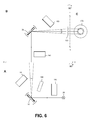
- FIGS. 6-8 show simplified representations of the illumination system of FIGS. 1-2 .
- FIGS. 9 and 10 show a simplified representations of an alternative embodiment of a mode-switchable illumination system of FIGS. 1-2
- FIGS. 1 and 2 show a schematic representation of an example of an illumination system for a microscope system capable of being mode-switchable between a first and a second illumination mode according to one embodiment of the present invention.
- the illumination system the first illumination mode is Total Internal Reflection (TIRF) and the second illumination mode is Photokinetics (PK) illumination.
- FIG. 1 shows the illumination system in TIRF mode
- FIG. 2 shows the illumination system in PK mode.
- the system comprises a source of illumination 20 , e.g. a laser source, arranged to provide a collimated beam of light 22 .
- a first scanning mirror 30 (also referred to as selector mirror in some embodiments) driven for scanning rotation about a first axis by a drive unit 40 , e.g. a galvo driver, a piezo driver or the like.
- the first scanning mirror is positioned in a first general direction to reflect the beam of light onto a second scanning mirror 50 driven for scanning rotation about a second axis of rotation, preferably transverse to the first, by a drive unit 60 .
- the second scanning mirror 50 is arranged in a first general position to redirect the beam of light along an exit beam path 52 whereby it passes through lens 160 arranged to focus the light beam at the back aperture of objective 170 .
- a control unit 200 is connected to and arranged to control the scan position of the first and second scanning mirrors 30 and 50 .
- the first and second scanning mirrors 30 and 50 are arranged to be scanned within their respective first general positions to thereby selectively position the exit beam of light at the, e.g. for scanning TIRF, desired positions at the edge of the back focal plane of the objective 170 as indicated by the dotted circle in FIG. 1 .
- the scanning TIRF mode is illustrated by two beam paths (solid and dotted) extending from the first scanning mirror 30 to the back aperture of the objective 170 .
- the disclosed embodiment is arranged to scan one beam of light and that each one of the disclosed beam path represents a two different mutual positions of the first and second scanning mirrors 30 and 50 respectively.
- FIG. 2 the system is shown in Photokinetics Illumination mode, wherein both first and second scanning mirrors 30 and 50 are arranged in a second general position, respectively.
- scanning mirror 30 redirects the beam of light into a first mirror loop 70 comprising mirrors 90 , 100 , 110 , 120 and 130 arranged to redirect the beam of light onto the first scanning mirror 30 a second time. Thereafter the beam of light is directed onto the second scanning mirror 50 .
- the second scanning mirror 50 is arranged to redirect the beam of light into a second mirror loop comprised of mirrors 140 and 150 which are arranged to redirect the beam of light onto the second scanning mirror 50 a second time.
- the Photokinetics Illumination mode involves scanning the angle of a collimated beam of light at the back aperture of the objective 170 . This results in scanning the position of the focused spot in the sample plane. In the disclosed system, this is accomplished by the incorporation of a lens 190 in the first mirror loop 70 arranged to focus the beam of light at a predetermined point along the beam path before the beam of light reaches lens 160 whereby the thus converging beam of light is re-collimated.
- the angle of the light beam at the back focal plane of the objective 170 may be scanned as the first and second scanning mirrors 30 and 50 are arranged to be scanned within their respective second general positions to thereby selectively position the exit beam of light.
- the first and second mirror loop arrangements may be designed to achieve a pure translation of the light beam.
- the first mirror loop comprising the lens 190 this is accomplished by means of an uneven number reflections of mirrors in the loop, and it should be noted that the disclosed embodiment using 5 static mirrors 90 , 100 , 110 , 120 and 130 in the loop should not be considered limiting but merely serve as an example of how such a loop may be designed.
- the first mirror loop may be designed using only two mirrors. In the embodiment of FIGS.
- the positioning of individual mirrors and other components represents one design wherein the optical path-lengths between different components have been taken into consideration in order to provide an functional and space effective illumination system.
- the mirrors 100 , 110 and 120 are included in the design to establish an elongated path-length between the first scanning mirror 30 and the lens 190 , as is further disclosed in FIG. 8 .
- the pure translation is achieved by 2 mirrors, but additional mirrors may be included also in the second loop to provide an elongated path-length if desired.
- the second scanning mirror may be omitted and the first scanning mirror may only have to be positioned in two fixed positions corresponding to the above general positions.
- the first scanning mirror is used both to direct the beam down separate paths and to redirect the beams from those two separate paths along a common exit path toward the objective lens.
- the optical elements e.g. lenses 160 and 190
- the optical elements may be replaced by one or more other optical element, such as a filter or other optical elements arranged to optically alter the beam of light, or they may be placed at different positions in the light path where they are included or excluded from the light path as controlled by switching the mirror loops in and out.
- FIGS. 3A-3B show a top-plan view and an isometric view of an example beam translator 600 comprising a mirror loop as disclosed in the previous embodiments.
- the translator 600 includes a scanning mirror 602 , a first flat stationary mirror 604 and a second flat stationary mirror 606 .
- the reflective surface of the stationary mirror 604 is angled toward the region between the scanning mirror 602 and stationary mirror 606
- the reflective surface of the stationary mirror 606 is angled toward the region between the scanning mirror 602 and the stationary mirror 604 .
- FIGS. 3A-3B show a top-plan view and an isometric view of an example beam translator 600 comprising a mirror loop as disclosed in the previous embodiments.
- the translator 600 includes a scanning mirror 602 , a first flat stationary mirror 604 and a second flat stationary mirror 606 .
- the reflective surface of the stationary mirror 604 is angled toward the region between the scanning mirror 602 and stationary mirror 606
- the reflective surface of the stationary mirror 606 is angled toward the region between the
- the scanning mirror 602 is a galvanometer mirror that includes a flat pivot mirror 608 attached to a rotatable shaft of a motor 610 , which can be a galvanometer motor or a stepper motor.
- the scanning mirror can be a piezoelectric controlled mirror. As shown in FIGS. 3A-3B , the mirror 608 is continuously rotated back and forth by the motor 610 through a range of angles.
- FIG. 4 shows a top-plan view of the beam translator 600 in operation.
- a beam of light 700 such as a beam of light output from the light source 102 as described above, is directed toward the mirror 608 .
- FIG. 4 shows the mirror 608 rotated in three positions 1, 2 and 3, which represent just three of a continuum of rotational positions for the mirror 608 .
- Differently patterned lines 701 - 703 represent three different paths the beam 700 travels through the translator 600 when the pivot mirror 608 is rotated into one of the three positions 1, 2 and 3, respectively.
- the stationary mirrors 604 and 606 and the pivot mirror 608 are positioned so that the beam is output along one of three substantially parallel paths via four reflections.
- the mirror 608 can be rotated into any of one of a continuum of positions that result in the beam being output from the translator 600 after four reflections along one of a continuum of substantially parallel paths.
- the output paths along which the output beam can travel are parallel or non-intersecting, but in practice, it is recognized that the paths may be only approximately parallel or intersect at very long distances away from the translator 600 due to slight variations in the relative placement and orientation of the mirrors. As a result, the paths along which the beam can be output from the translator 600 are referred to as approximately parallel.
- FIGS. 5A-5C show snapshots of internal paths the beam 700 traveling through the translator 600 when the pivot mirror 608 is rotated into the three positions 1, 2 and 3, respectively.
- the pivot mirror 608 is rotated into position 1.
- the beam 700 strikes the pivot mirror 608 at the point 802 and undergoes four reflections off of the mirrors 604 , 606 and 608 with the reflections numbered sequentially 1, 2, 3 and 4.
- the 4 th reflection off of the pivot mirror 608 at the point 804 places the beam on the path 701 also shown in FIG. 8 .
- the pivot mirror 608 is rotated into position 2.
- the beam 700 strikes the pivot mirror 608 at the point 806 and undergoes four reflections off of the mirrors 604 , 606 and 608 with the reflections numbered sequentially 1′, 2′, 3′ and 4′.
- the 4′ th reflection off of the pivot mirror 608 near the point 806 places the beam on the path 702 also shown in FIG. 8 .
- the pivot mirror or 608 is rotated into position 3.
- the beam 700 strikes the pivot mirror 608 at the point 808 and undergoes four reflections off of the mirrors 604 , 606 and 608 with the reflections numbered sequentially 1′′, 2′′, 3′′ and 4′′.
- the 4′′ th reflection off of the pivot mirror 608 at the point 810 places the beam on the path 703 also shown in FIG. 8 .
- the beam translator 600 When the beam translator 600 is implemented with a galvanometer mirror for the scanning mirror 602 sub-millisecond translation of the output beam is attainable.
- FIGS. 6 and 7 shows a general representation of the illumination system of FIGS. 1 and 2 , but wherein the 3-dimensional representation of the system and the beam path has been transformed into a simplified 2 dimensional figure based on the beam translator 600 of FIG. 3-5 .
- the first and second scanning mirrors 30 and 50 and their associated mirrors have been separated into two schematic beam translator sections, A and B respectively.
- the beam translator of section A is shown rotated by approximately 90° with respect to the beam translator of section B.
- the angle of rotation of the two sections A and B with respect to each other need not to be exactly 90°, but that it is sufficient that the rotation is large enough to achieve the desired scanning capability of the output beam of light from the system.
- the first scan/selector mirror 30 of section A is arranged to scan the beam of light in a first dimension, i.e. a first scan plane
- the second scan mirror 50 of section B is arranged to scan the beam of light in a second dimension, second scan plane, which is essentially orthogonal to the first dimension.
- FIGS. 6 and 7 also the back end of the objective 170 is shown rotated by 90° with respect to the beam translator of section B in order to better display the output beam of light from the illumination system.
- mirrors 100 , 110 and 120 of FIGS. 1 and 2 are omitted in order to more clearly show the basic principles of the switching between a first and a second illumination mode using beam translator sections A and B.
- FIG. 8 shows a corresponding simplified representation of an illumination system comprising said mirrors to provide an elongated or otherwise reconfigured optical path.
- both beam translator sections A and B respectively are arranged to provide essentially parallel translation of the beam of light.
- the beam translator section A may be used as a pure mode switch for selectively switching one or more optical elements into and out of the optical beam path of an illumination system.
- the scan mirror 50 of previous embodiments is replaced by a scan mirror 210 capable of scanning in 2 dimensions in order to provide the desired scanning of the output light beam.
- the illumination system capable of being mode-switchable between a first and a second illumination mode may e.g. be provided as a modular add on unit for a suitable microscope system, or it may be integrated as an integral part of a microscope, and it should be noted that the illumination system need not to be limited to switching between two illumination modes, but it may provide a broad ranges of illumination modes as well as suitable intermediate illumination modes.
Landscapes
- Physics & Mathematics (AREA)
- General Physics & Mathematics (AREA)
- Chemical & Material Sciences (AREA)
- Analytical Chemistry (AREA)
- Optics & Photonics (AREA)
- Health & Medical Sciences (AREA)
- Nuclear Medicine, Radiotherapy & Molecular Imaging (AREA)
- Life Sciences & Earth Sciences (AREA)
- Biochemistry (AREA)
- General Health & Medical Sciences (AREA)
- Immunology (AREA)
- Pathology (AREA)
- Microscoopes, Condenser (AREA)
- Mechanical Optical Scanning Systems (AREA)
Abstract
Description
Claims (6)
Priority Applications (1)
| Application Number | Priority Date | Filing Date | Title |
|---|---|---|---|
| US14/356,410 US9507136B2 (en) | 2011-11-15 | 2012-11-14 | Mode-switchable illumination system for a microscope |
Applications Claiming Priority (3)
| Application Number | Priority Date | Filing Date | Title |
|---|---|---|---|
| US201161560056P | 2011-11-15 | 2011-11-15 | |
| US14/356,410 US9507136B2 (en) | 2011-11-15 | 2012-11-14 | Mode-switchable illumination system for a microscope |
| PCT/SE2012/051260 WO2013074033A1 (en) | 2011-11-15 | 2012-11-14 | Mode-switchable illumination system for a microscope |
Publications (2)
| Publication Number | Publication Date |
|---|---|
| US20140320958A1 US20140320958A1 (en) | 2014-10-30 |
| US9507136B2 true US9507136B2 (en) | 2016-11-29 |
Family
ID=48429963
Family Applications (1)
| Application Number | Title | Priority Date | Filing Date |
|---|---|---|---|
| US14/356,410 Expired - Fee Related US9507136B2 (en) | 2011-11-15 | 2012-11-14 | Mode-switchable illumination system for a microscope |
Country Status (4)
| Country | Link |
|---|---|
| US (1) | US9507136B2 (en) |
| EP (1) | EP2780753B1 (en) |
| JP (1) | JP6117227B2 (en) |
| WO (1) | WO2013074033A1 (en) |
Cited By (1)
| Publication number | Priority date | Publication date | Assignee | Title |
|---|---|---|---|---|
| US10884227B2 (en) | 2016-11-10 | 2021-01-05 | The Trustees Of Columbia University In The City Of New York | Rapid high-resolution imaging methods for large samples |
Families Citing this family (6)
| Publication number | Priority date | Publication date | Assignee | Title |
|---|---|---|---|---|
| DE102014108259A1 (en) * | 2014-06-12 | 2015-12-17 | Scanlab Ag | Device for laser material processing |
| EP3021153B1 (en) | 2014-11-13 | 2018-12-12 | Canon Kabushiki Kaisha | Optical apparatus, processing apparatus, and article manufacturing method |
| JP6595879B2 (en) * | 2014-11-13 | 2019-10-23 | キヤノン株式会社 | Optical apparatus, processing apparatus, and article manufacturing method |
| US9964754B2 (en) * | 2015-12-11 | 2018-05-08 | Finger Lakes Instrumentation, Llc | Method, apparatus, and computer-readable medium for switching optical paths |
| DE102017119479A1 (en) * | 2017-08-25 | 2019-02-28 | Carl Zeiss Microscopy Gmbh | Optical arrangement for scanning excitation radiation and / or manipulation radiation in a laser scanning microscope and laser scanning microscope |
| DE102025100905B3 (en) * | 2025-01-13 | 2026-01-29 | Acal Bfi Germany Gmbh | XY deflection unit for laser light with two operating modes and their use |
Citations (11)
| Publication number | Priority date | Publication date | Assignee | Title |
|---|---|---|---|---|
| US5861982A (en) | 1995-06-23 | 1999-01-19 | Olympus Optical Co., Ltd. | Optical-path switching apparatus, optical-device switching apparatus for optical microscope and locking apparatus for use in transporting optical microscope |
| US20020048025A1 (en) | 2000-08-12 | 2002-04-25 | Hideyuki Takaoka | Optical system and optical apparatus |
| US20020154311A1 (en) | 2001-03-14 | 2002-10-24 | Biacore Ab | Apparatus and method for total internal reflection spectroscopy |
| US20030058530A1 (en) | 2001-09-25 | 2003-03-27 | Yoshihiro Kawano | Microscope switchable between observation modes |
| US20040246575A1 (en) | 2003-06-03 | 2004-12-09 | Olympus Corporation | Illumination unit of stereomicroscope |
| US20050179903A1 (en) | 2004-02-09 | 2005-08-18 | Olympus Corporation | Total internal reflection fluorescence microscope |
| US20060028718A1 (en) | 2002-07-12 | 2006-02-09 | Olympus Biosystems Gmbh | Illuminating device and optical object-analyzing device |
| WO2008009581A1 (en) | 2006-07-17 | 2008-01-24 | Leica Microsystems Cms Gmbh | Tirf microscope |
| US7573635B2 (en) * | 2005-11-11 | 2009-08-11 | Till I.D. Gmbh | Microscope device |
| US7715078B2 (en) * | 2005-12-28 | 2010-05-11 | Nikon Corporation | Optical scan device, optical scan type microscope, observation method, control device, and control program |
| US20110069382A1 (en) | 2008-03-26 | 2011-03-24 | Derek Kalev Toomre | Optical system that selectively provides either of a collimated light beam or a convergent light beam |
-
2012
- 2012-11-14 EP EP12850201.0A patent/EP2780753B1/en not_active Not-in-force
- 2012-11-14 US US14/356,410 patent/US9507136B2/en not_active Expired - Fee Related
- 2012-11-14 JP JP2014541008A patent/JP6117227B2/en not_active Expired - Fee Related
- 2012-11-14 WO PCT/SE2012/051260 patent/WO2013074033A1/en not_active Ceased
Patent Citations (11)
| Publication number | Priority date | Publication date | Assignee | Title |
|---|---|---|---|---|
| US5861982A (en) | 1995-06-23 | 1999-01-19 | Olympus Optical Co., Ltd. | Optical-path switching apparatus, optical-device switching apparatus for optical microscope and locking apparatus for use in transporting optical microscope |
| US20020048025A1 (en) | 2000-08-12 | 2002-04-25 | Hideyuki Takaoka | Optical system and optical apparatus |
| US20020154311A1 (en) | 2001-03-14 | 2002-10-24 | Biacore Ab | Apparatus and method for total internal reflection spectroscopy |
| US20030058530A1 (en) | 2001-09-25 | 2003-03-27 | Yoshihiro Kawano | Microscope switchable between observation modes |
| US20060028718A1 (en) | 2002-07-12 | 2006-02-09 | Olympus Biosystems Gmbh | Illuminating device and optical object-analyzing device |
| US20040246575A1 (en) | 2003-06-03 | 2004-12-09 | Olympus Corporation | Illumination unit of stereomicroscope |
| US20050179903A1 (en) | 2004-02-09 | 2005-08-18 | Olympus Corporation | Total internal reflection fluorescence microscope |
| US7573635B2 (en) * | 2005-11-11 | 2009-08-11 | Till I.D. Gmbh | Microscope device |
| US7715078B2 (en) * | 2005-12-28 | 2010-05-11 | Nikon Corporation | Optical scan device, optical scan type microscope, observation method, control device, and control program |
| WO2008009581A1 (en) | 2006-07-17 | 2008-01-24 | Leica Microsystems Cms Gmbh | Tirf microscope |
| US20110069382A1 (en) | 2008-03-26 | 2011-03-24 | Derek Kalev Toomre | Optical system that selectively provides either of a collimated light beam or a convergent light beam |
Non-Patent Citations (1)
| Title |
|---|
| Supplementary European Search Report for EP Application No. 12850201.0 mailed Jun. 1, 2015 (5 pages). |
Cited By (2)
| Publication number | Priority date | Publication date | Assignee | Title |
|---|---|---|---|---|
| US10884227B2 (en) | 2016-11-10 | 2021-01-05 | The Trustees Of Columbia University In The City Of New York | Rapid high-resolution imaging methods for large samples |
| US11506877B2 (en) | 2016-11-10 | 2022-11-22 | The Trustees Of Columbia University In The City Of New York | Imaging instrument having objective axis and light sheet or light beam projector axis intersecting at less than 90 degrees |
Also Published As
| Publication number | Publication date |
|---|---|
| WO2013074033A1 (en) | 2013-05-23 |
| EP2780753A1 (en) | 2014-09-24 |
| EP2780753A4 (en) | 2015-07-15 |
| US20140320958A1 (en) | 2014-10-30 |
| EP2780753B1 (en) | 2017-09-13 |
| JP2014533377A (en) | 2014-12-11 |
| JP6117227B2 (en) | 2017-04-19 |
Similar Documents
| Publication | Publication Date | Title |
|---|---|---|
| US9507136B2 (en) | Mode-switchable illumination system for a microscope | |
| JP5525136B2 (en) | Optical device for generating sheet light | |
| US9411144B2 (en) | Systems for fluorescence illumination using superimposed polarization states | |
| US9606342B2 (en) | Laser beam selectors | |
| JP5194169B2 (en) | An optical system that selectively provides either a collimated light beam or a convergent light beam | |
| US7187494B2 (en) | Laser microscope | |
| US8559103B2 (en) | Microscope for conventional fluorescence microscopy and total internal reflection microscopy | |
| CN105283792A (en) | Method and optical arrangement for manipulating and imaging a microscopic sample | |
| JP2007506955A (en) | Scanning microscope with evanescent wave illumination | |
| CN105527261A (en) | A multi-mode scanning device of a two-photon fluorescence microscope | |
| JP2016529558A (en) | Side illumination microscope system and microscope method | |
| US20220397751A1 (en) | Re-scan microscope system and method | |
| US10025081B2 (en) | Microscope for evanescent illumination and point-shaped raster illumination | |
| JP5633706B2 (en) | Confocal light scanner and confocal microscope | |
| JP5734758B2 (en) | Laser microscope | |
| EP2666049B1 (en) | Light-scanning systems | |
| JP2013156286A (en) | Imaging apparatus | |
| US9599803B2 (en) | Beam combiner for combining two independently scanned illuminating beams of a light scanning microscope | |
| JP2004021259A (en) | Optical device for acquiring information on a sample or observation object | |
| CN205620304U (en) | Two -photon fluorescence microscope's multimode scanning device | |
| US10295469B2 (en) | Temporal focusing-based multiphoton excitation fluorescence microscopy system capable of tunable-wavelength excitation and excitation wavelength selection module thereof | |
| JP4563699B2 (en) | Lighting switching device | |
| JP2018036337A (en) | Microscope system | |
| JP2011501244A (en) | Scanning confocal microscopy and related improvements | |
| JPH102860A (en) | Micro-substance inspection lens device |
Legal Events
| Date | Code | Title | Description |
|---|---|---|---|
| AS | Assignment |
Owner name: APPLIED PRECISION, INC., WASHINGTON Free format text: ASSIGNMENT OF ASSIGNORS INTEREST;ASSIGNORS:COOPER, JEREMY R.;DOUGHERTY, WILLIAM M.;REESE, STEVEN A.;REEL/FRAME:032828/0044 Effective date: 20130125 Owner name: GE HEALTHCARE BIO-SCIENCES CORP., NEW JERSEY Free format text: MERGER;ASSIGNOR:APPLIED PRECISION, INC.;REEL/FRAME:032828/0084 Effective date: 20130701 |
|
| STCF | Information on status: patent grant |
Free format text: PATENTED CASE |
|
| MAFP | Maintenance fee payment |
Free format text: PAYMENT OF MAINTENANCE FEE, 4TH YEAR, LARGE ENTITY (ORIGINAL EVENT CODE: M1551); ENTITY STATUS OF PATENT OWNER: LARGE ENTITY Year of fee payment: 4 |
|
| AS | Assignment |
Owner name: GLOBAL LIFE SCIENCES SOLUTIONS USA LLC, MASSACHUSETTS Free format text: CHANGE OF NAME;ASSIGNOR:GE HEALTHCARE BIO-SCIENCES CORP.;REEL/FRAME:053648/0854 Effective date: 20190930 |
|
| AS | Assignment |
Owner name: LEICA MICROSYSTEMS CMS GMBH, GERMANY Free format text: ASSIGNMENT OF ASSIGNORS INTEREST;ASSIGNOR:GLOBAL LIFE SCIENCES SOLUTIONS USA LLC;REEL/FRAME:057261/0128 Effective date: 20210430 |
|
| FEPP | Fee payment procedure |
Free format text: MAINTENANCE FEE REMINDER MAILED (ORIGINAL EVENT CODE: REM.); ENTITY STATUS OF PATENT OWNER: LARGE ENTITY |
|
| LAPS | Lapse for failure to pay maintenance fees |
Free format text: PATENT EXPIRED FOR FAILURE TO PAY MAINTENANCE FEES (ORIGINAL EVENT CODE: EXP.); ENTITY STATUS OF PATENT OWNER: LARGE ENTITY |
|
| STCH | Information on status: patent discontinuation |
Free format text: PATENT EXPIRED DUE TO NONPAYMENT OF MAINTENANCE FEES UNDER 37 CFR 1.362 |
|
| FP | Lapsed due to failure to pay maintenance fee |
Effective date: 20241129 |