US9506646B1 - Apparatus and method for linear mixing tube assembly - Google Patents
Apparatus and method for linear mixing tube assembly Download PDFInfo
- Publication number
- US9506646B1 US9506646B1 US14/041,718 US201314041718A US9506646B1 US 9506646 B1 US9506646 B1 US 9506646B1 US 201314041718 A US201314041718 A US 201314041718A US 9506646 B1 US9506646 B1 US 9506646B1
- Authority
- US
- United States
- Prior art keywords
- mixing tube
- mixing
- turbulator
- cylindrical outer
- inlet end
- Prior art date
- Legal status (The legal status is an assumption and is not a legal conclusion. Google has not performed a legal analysis and makes no representation as to the accuracy of the status listed.)
- Active, expires
Links
Images


Classifications
-
- F—MECHANICAL ENGINEERING; LIGHTING; HEATING; WEAPONS; BLASTING
- F23—COMBUSTION APPARATUS; COMBUSTION PROCESSES
- F23D—BURNERS
- F23D14/00—Burners for combustion of a gas, e.g. of a gas stored under pressure as a liquid
- F23D14/02—Premix gas burners, i.e. in which gaseous fuel is mixed with combustion air upstream of the combustion zone
-
- F—MECHANICAL ENGINEERING; LIGHTING; HEATING; WEAPONS; BLASTING
- F23—COMBUSTION APPARATUS; COMBUSTION PROCESSES
- F23C—METHODS OR APPARATUS FOR COMBUSTION USING FLUID FUEL OR SOLID FUEL SUSPENDED IN A CARRIER GAS OR AIR
- F23C7/00—Combustion apparatus characterised by arrangements for air supply
- F23C7/002—Combustion apparatus characterised by arrangements for air supply the air being submitted to a rotary or spinning motion
- F23C7/004—Combustion apparatus characterised by arrangements for air supply the air being submitted to a rotary or spinning motion using vanes
-
- F—MECHANICAL ENGINEERING; LIGHTING; HEATING; WEAPONS; BLASTING
- F23—COMBUSTION APPARATUS; COMBUSTION PROCESSES
- F23D—BURNERS
- F23D11/00—Burners using a direct spraying action of liquid droplets or vaporised liquid into the combustion space
- F23D11/36—Details
- F23D11/40—Mixing tubes; Burner heads
-
- F—MECHANICAL ENGINEERING; LIGHTING; HEATING; WEAPONS; BLASTING
- F23—COMBUSTION APPARATUS; COMBUSTION PROCESSES
- F23D—BURNERS
- F23D14/00—Burners for combustion of a gas, e.g. of a gas stored under pressure as a liquid
- F23D14/34—Burners specially adapted for use with means for pressurising the gaseous fuel or the combustion air
- F23D14/36—Burners specially adapted for use with means for pressurising the gaseous fuel or the combustion air in which the compressor and burner form a single unit
-
- F—MECHANICAL ENGINEERING; LIGHTING; HEATING; WEAPONS; BLASTING
- F23—COMBUSTION APPARATUS; COMBUSTION PROCESSES
- F23D—BURNERS
- F23D14/00—Burners for combustion of a gas, e.g. of a gas stored under pressure as a liquid
- F23D14/46—Details
- F23D14/62—Mixing devices; Mixing tubes
-
- F—MECHANICAL ENGINEERING; LIGHTING; HEATING; WEAPONS; BLASTING
- F23—COMBUSTION APPARATUS; COMBUSTION PROCESSES
- F23D—BURNERS
- F23D14/00—Burners for combustion of a gas, e.g. of a gas stored under pressure as a liquid
- F23D14/46—Details
- F23D14/70—Baffles or like flow-disturbing devices
Definitions
- the present invention relates generally to burner assemblies, and particularly to devices adapted to mix air and fuel in burner assemblies.
- flow straightening device means any device, mechanism, assembly or combination thereof that is adapted to facilitate the flow of air, fuel or a mixture of air and fuel in a burner assembly in a direction generally parallel to the longitudinal axis of the burner assembly.
- turbulator means swirlers, curved vanes, bluff bodies, tabs, lips, surface treatments and/or any other suitable device, mechanism, assembly or combination thereof which is adapted to mix fuel and air.
- the apparatus of the invention comprises a mixing tube assembly having an inlet end and an outlet end and being adapted for use in a burner assembly.
- the mixing tube assembly comprises a substantially cylindrical outer wall which defines an interior open space.
- the mixing tube assembly also comprises a turbulator that is disposed in the interior open space defined by the substantially cylindrical outer wall and a flow straightening device that is disposed downstream from the turbulator.
- the method of the invention comprises a method for mixing fuel and air in a burner assembly.
- the preferred method comprises providing a mixing tube assembly having an inlet end and an outlet end.
- the preferred mixing tube assembly comprises a substantially cylindrical outer wall that defines an interior open space.
- the preferred mixing tube assembly also comprises a turbulator that is disposed in the interior open space defined by the substantially cylindrical outer wall and a flow straightening device that is disposed downstream from the turbulator.
- the preferred method also comprises conveying fuel and air from the inlet end of the mixing tube assembly to the outlet end of the mixing tube assembly and straightening the gaseous fuel and air mixture flow in the mixing tube assembly.
- FIG. 1 is a perspective view of the preferred mixing tube assembly in accordance with the present invention.
- FIG. 2 is a partial sectional perspective view of an exemplary burner assembly including a plurality of the preferred mixing tube assemblies illustrated in FIG. 1 .
- FIG. 3 is a partial sectional perspective view of the exemplary burner assembly including a plurality of the preferred mixing tube assemblies illustrated in FIGS. 1 and 2 .
- FIG. 4 is an end view of the exemplary mixing section including a plurality of the preferred mixing tube assemblies illustrated in FIGS. 1 through 3 .
- FIG. 5 is a perspective view of the exemplary mixing section including a plurality of the preferred mixing tube assemblies illustrated in FIGS. 1 through 4 .
- FIG. 6 is a perspective view of the exemplary mixing section including a plurality of the preferred mixing tube assemblies illustrated in FIGS. 1 through 5 .
- FIG. 7 is a perspective view of a conventional mixing tube showing the concentration of gaseous fuel across a cross-sectional plane 28 inches downstream from the inlet end.
- FIG. 8 is a perspective view of the preferred mixing tube assembly illustrated in FIGS. 1-6 showing the concentration of gaseous fuel across a cross-sectional plane 24 inches downstream from the inlet end.
- FIG. 9 is a chart illustrating the concentration of gaseous fuel at different radial distances for a conventional mixing tube and the preferred mixing tube assembly illustrated in FIGS. 1-6 and 8 .
- FIG. 10 is a perspective front view of a first alternative embodiment of the preferred linear mixing tube in accordance with the present invention.
- FIG. 11 is a perspective sectional front view of the first alternative embodiment of the preferred linear mixing tube illustrated in FIG. 10 .
- FIG. 12 is a sectional front view of the first alternative embodiment of the preferred linear mixing tube illustrated in FIGS. 10-11 .
- FIG. 13 is a right side view of the first alternative embodiment of the preferred linear mixing tube illustrated in FIGS. 10-12 .
- FIG. 14 is a left side view of the first alternative embodiment of the preferred linear mixing tube illustrated in FIGS. 10-13 .
- FIG. 15 is a perspective front view of an exemplary mixing section comprising a plurality of the first alternative embodiment of the preferred linear mixing tubes illustrated in FIGS. 10-14 .
- FIG. 16 is a perspective partial sectional front view of an exemplary burner assembly comprising the preferred mixing section illustrated in FIG. 15 .
- FIG. 17 is a partial sectional front view of the exemplary burner assembly comprising the preferred mixing section illustrated in FIGS. 15-16 .
- FIG. 18 is a right side view of the first alternative embodiment of the exemplary burner assembly comprising the preferred mixing section illustrated in FIGS. 15-17 .
- FIGS. 1 through 6, 8 through 18 the preferred embodiment of the apparatus and method for a mixing tube assembly in accordance with the present invention is illustrated by FIGS. 1 through 6, 8 through 18 .
- the preferred embodiments of the apparatus and method for a mixing tube assembly are adapted to mix air and fuel in a burner assembly that reduces the size and cost of manufacture and operation.
- the preferred embodiments of the apparatus and method for a mixing tube assembly are also adapted to mix air and fuel more efficiently, completely and uniformly.
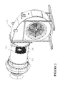
- FIG. 1 a perspective view of the preferred mixing tube assembly in accordance with the present invention is illustrated.
- the preferred mixing tube assembly is designated generally by reference numeral 20 .
- Preferred mixing tube assembly 20 has inlet end 22 and outlet end 24 .
- Preferred mixing tube assembly 20 is adapted for use in a burner assembly such as a gaseous burner assembly, however, it is contemplated within the scope of the invention that the mixing tube assembly could be adapted for use in other suitable items of equipment or applications.
- Preferred mixing tube assembly 20 comprises substantially cylindrical outer wall 26 which defines interior open space 28 .
- Preferred mixing tube assembly 20 further comprises turbulator 30 .
- Preferred turbulator 30 is disposed in interior open space 28 defined by substantially cylindrical outer wall 26 .
- preferred substantially cylindrical outer wall 26 of mixing tube assembly 20 includes inlet end flare 32 .
- Preferred inlet end flare 32 of substantially cylindrical outer wall 26 is disposed at inlet end 22 of mixing tube assembly 20 .
- Preferred turbulator 30 is disposed in inlet end 22 of mixing tube assembly 20 .
- preferred turbulator 30 comprises swirler 34 .
- Preferred swirler 34 is disposed in inlet end flare 32 of substantially cylindrical outer wall 26 and comprises plurality of curved vanes 36 .
- swirler 34 is attached to plurality of tabs 38 .
- Preferred plurality of tabs 38 are disposed in inlet end 22 of mixing tube assembly 20 and attached to retainer ring 40 which is also disposed in the inlet end of the mixing tube assembly.
- Preferred turbulator 30 also comprises bluff body 42 .
- Preferred bluff body 42 is spaced apart from substantially cylindrical outer wall 26 and disposed in inlet end 22 of mixing tube assembly 20 .
- Preferred bluff body 42 is also attached to swirler 34 , however, it is contemplated within the scope of the invention that the bluff body is not attached to the swirler.
- FIG. 2 a partial sectional perspective view of exemplary burner assembly 50 including a plurality of preferred mixing tube assemblies 20 is illustrated. As shown in FIG. 2 , the preferred plurality of mixing tube assemblies 20 are disposed in mixing section 52 of burner assembly 50 . Preferred mixing section 52 further comprises inlet end tube sheet 54 . While preferred mixing section 52 comprises a plurality of mixing tube assemblies 20 , it is contemplated within the scope of the invention that mixing section 52 comprises only one mixing tube assembly.
- preferred mixing section 52 comprises inlet end flare 32 , swirler 34 , tabs 38 , bluff body 42 and inlet end tube sheet 54 .
- exemplary mixing section 52 including a plurality of the preferred mixing tube assemblies 20 is illustrated.
- preferred mixing section 52 includes inlet end flare 32 , swirler 34 , bluff body 42 and inlet end tube sheet 54 .
- preferred mixing section 52 includes inlet end flare 32 , swirler 34 , bluff body 42 and inlet end tube sheet 54 .
- exemplary mixing section 52 including a plurality of the preferred mixing tube assemblies 20 is illustrated. As shown in FIG. 6 , preferred mixing section 52 includes outlet end 24 of mixing tube assemblies 20 and outlet end tube sheet 56 .
- FIG. 7 a perspective view of a conventional mixing tube showing the concentration of gaseous fuel across a cross-sectional plane 28 inches downstream from inlet end 62 is illustrated.
- the conventional mixing tube is designated generally by reference numeral 60 .
- Conventional mixing tube 60 causes the concentration of gaseous fuel within the tube to increase near the outer wall and to decrease near the center of the tube.
- FIG. 8 a perspective view of preferred mixing tube assembly 20 showing the concentration of gaseous fuel across a cross-sectional plane 24 inches downstream from inlet end 22 is illustrated. As shown in FIG. 8 , preferred mixing tube assembly 20 causes the concentration of gaseous fuel within the tube to more uniform and in a shorter distance than conventional mixing tube 60 .
- FIG. 9 a chart illustrating the concentration of gaseous fuel at different radial distances for conventional mixing tube 60 and the preferred mixing tube assembly 20 is illustrated.
- the chart is generally designated by reference numeral 70 .
- points 72 represent the gas concentration at different radial distances in conventional mixing tube 60 and points 74 represent the gas concentration at different radial distances in preferred mixing tube 20 .
- chart 70 illustrates the mass fraction of methane at radial units (meters) at 28 inches downstream from inlet end 62 of conventional mixing tube 60 and at 24 inches downstream from inlet end 22 of preferred mixing tube assembly 20 .
- FIG. 10 a perspective front view of a first alternative embodiment of the preferred linear mixing tube in accordance with the present invention is illustrated.
- the preferred linear mixing tube is designated generally by reference numeral 100 .
- Preferred linear mixing tube 100 is adapted to straighten the flow of the air and fuel mixture before it exits the tube so as to minimize or eliminate turbulence between flows from adjacent tubes. More particularly, preferred linear mixing tube 100 comprises inlet end 102 and outlet end 104 .
- Preferred linear mixing tube 100 also comprises flow straightening device 106 which is adapted to straighten the flow of the air and fuel mixture in the mixing tube assembly. Preferably, flow straightening device 106 is disposed adjacent to outlet end 104 and inside outer sleeve 108 . While FIG. 10 illustrates the preferred configuration and arrangement of the flow straightening device, it is contemplated within the scope of the invention that the flow straightening device may be of any suitable configuration and arrangement.
- preferred linear mixing tube 100 comprises inlet end 102 , outlet end 104 , flow straightening device 106 , and outer sleeve 108 .
- Preferred linear mixing tube 100 also comprises turbulator 110 .
- turbulator 110 is disposed adjacent to inlet end 102
- flow straightening device 106 is disposed downstream from turbulator 110 .
- Preferred turbulator 110 is adapted to uniformly and completely mix air and fuel in a burner assembly. While FIG. 11 illustrates the preferred configuration and arrangement of the turbulator, it is contemplated within the scope of the invention that the turbulator may be of any suitable configuration and arrangement.
- preferred linear mixing tube 100 comprises inlet end 102 , outlet end 104 , flow straightening device 106 , outer sleeve 108 , and turbulator 110 .
- preferred linear mixing tube 100 comprises flow straightening device 106 , outer sleeve 108 , and turbulator 110 .
- preferred linear mixing tube 100 comprises flow straightening device 106 and turbulator 110 .
- FIG. 15 a perspective front view of an exemplary mixing section comprising a plurality of preferred linear mixing tubes 100 is illustrated.
- the exemplary mixing section is designated generally by reference numeral 116 .
- Exemplary mixing section 116 comprises linear mixing tubes 100 having inlet ends 102 , outlet ends 104 , and flow straightening devices 106 .
- Exemplary mixing section also comprises inlet end tube sheet 112 and outlet end tube sheet 114 . While FIG. 15 illustrates the preferred configuration and arrangement of the exemplary mixing section comprising a plurality of preferred linear mixing tubes, it is contemplated within the scope of the invention that the mixing section may be of any suitable configuration and arrangement.
- FIG. 16 a perspective partial sectional front view of an exemplary burner assembly comprising preferred mixing section 116 is illustrated.
- the exemplary burner is designated generally by reference numeral 118 .
- Preferred burner assembly 118 comprises longitudinal axis 120 .
- flow straightening devices 106 are adapted to facilitate the flow of the air and fuel mixture in a direction that is generally parallel to longitudinal axis 120 of burner assembly 118 .
- exemplary burner assembly 118 comprising preferred mixing section 116 is illustrated.
- exemplary burner assembly comprises an upstream end 122 and a downstream end 124 .
- the turbulators are disposed closer to upstream end 122 than the flow straightening devices, and the flow straightening devices are disposed closer to downstream end 124 than the turbulators.
- FIG. 18 a right end view of exemplary burner assembly 118 comprising preferred mixing section 116 is illustrated. While FIGS. 16-18 illustrate the preferred configuration and arrangement of the burner assembly and mixing section, it is contemplated within the scope of the invention that the burner assembly and mixing section may be of any suitable configuration and arrangement.
- the invention also comprises a method for mixing fuel and air in a burner assembly.
- the preferred method comprises providing a mixing tube assembly having an inlet end and an outlet end.
- the preferred mixing tube assembly comprises a substantially cylindrical outer wall which defines an interior open space.
- the preferred mixing tube assembly also comprises a turbulator that is disposed in the interior open space defined by the substantially cylindrical outer wall and a flow straightening device that is disposed downstream from the turbulator.
- the preferred method also comprises conveying fuel and air from the inlet end of the mixing tube assembly to the outlet end of the mixing tube assembly.
- the method comprises a turbulator having a retainer ring that is disposed at the inlet end of the mixing tube assembly, a plurality of tabs that are attached to the retainer ring, a swirler that is attached to the plurality of tabs and a bluff body that is attached to the swirler.
- the method comprises mixing gaseous fuel and air in the mixing tube assembly, and straightening the gaseous fuel and air mixture flow in the mixing tube assembly.
- the preferred embodiments of the apparatus and method for a mixing tube assembly are adapted to mix air and fuel in a burner assembly that reduces the size and cost of manufacture and operation.
- the preferred embodiments of the apparatus and method for a mixing tube assembly are also adapted to mix air and fuel more efficiently, completely and uniformly.
- the preferred embodiments of the apparatus and method for a mixing tube assembly are adapted to straighten the gaseous fuel and air mixture flow in the mixing tube so as to minimize or eliminate turbulence between flows from other mixing tube assemblies.
Landscapes
- Engineering & Computer Science (AREA)
- Chemical & Material Sciences (AREA)
- Combustion & Propulsion (AREA)
- Mechanical Engineering (AREA)
- General Engineering & Computer Science (AREA)
- Gas Burners (AREA)
Abstract
Description
Claims (15)
Priority Applications (1)
| Application Number | Priority Date | Filing Date | Title |
|---|---|---|---|
| US14/041,718 US9506646B1 (en) | 2011-03-16 | 2013-09-30 | Apparatus and method for linear mixing tube assembly |
Applications Claiming Priority (4)
| Application Number | Priority Date | Filing Date | Title |
|---|---|---|---|
| US201161465215P | 2011-03-16 | 2011-03-16 | |
| US13/422,228 US9188330B1 (en) | 2011-03-16 | 2012-03-16 | Apparatus and method for mixing tube assembly |
| US201261744690P | 2012-10-02 | 2012-10-02 | |
| US14/041,718 US9506646B1 (en) | 2011-03-16 | 2013-09-30 | Apparatus and method for linear mixing tube assembly |
Related Parent Applications (1)
| Application Number | Title | Priority Date | Filing Date |
|---|---|---|---|
| US13/422,228 Continuation-In-Part US9188330B1 (en) | 2011-03-16 | 2012-03-16 | Apparatus and method for mixing tube assembly |
Publications (1)
| Publication Number | Publication Date |
|---|---|
| US9506646B1 true US9506646B1 (en) | 2016-11-29 |
Family
ID=57351923
Family Applications (1)
| Application Number | Title | Priority Date | Filing Date |
|---|---|---|---|
| US14/041,718 Active 2033-06-04 US9506646B1 (en) | 2011-03-16 | 2013-09-30 | Apparatus and method for linear mixing tube assembly |
Country Status (1)
| Country | Link |
|---|---|
| US (1) | US9506646B1 (en) |
Cited By (2)
| Publication number | Priority date | Publication date | Assignee | Title |
|---|---|---|---|---|
| US20160334134A1 (en) * | 2015-05-14 | 2016-11-17 | Lochinvar, Llc | Burner With Flow Distribution Member |
| US20230266003A1 (en) * | 2022-02-22 | 2023-08-24 | Honeywell International Inc. | Ultra-low nox multi-port burner apparatus |
Citations (5)
| Publication number | Priority date | Publication date | Assignee | Title |
|---|---|---|---|---|
| US3811816A (en) * | 1973-01-29 | 1974-05-21 | Gen Electric | Acoustic flame detectors for steam generators |
| NL1008233C2 (en) * | 1998-02-06 | 1999-08-09 | Clysan D W Bv | Forced injection gas burner for boiler or furnace |
| CA2260636A1 (en) * | 1998-02-09 | 1999-08-09 | Shigemi Mandai | Gas turbine combustor |
| US20100263381A1 (en) * | 2006-04-14 | 2010-10-21 | Koichi Ishizaka | Premixed combustion burner for gas turbine |
| US20100269508A1 (en) * | 2007-11-29 | 2010-10-28 | Mitsubishi Heavy Industries, Ltd. | Combustion burner |
-
2013
- 2013-09-30 US US14/041,718 patent/US9506646B1/en active Active
Patent Citations (6)
| Publication number | Priority date | Publication date | Assignee | Title |
|---|---|---|---|---|
| US3811816A (en) * | 1973-01-29 | 1974-05-21 | Gen Electric | Acoustic flame detectors for steam generators |
| NL1008233C2 (en) * | 1998-02-06 | 1999-08-09 | Clysan D W Bv | Forced injection gas burner for boiler or furnace |
| CA2260636A1 (en) * | 1998-02-09 | 1999-08-09 | Shigemi Mandai | Gas turbine combustor |
| US6209326B1 (en) * | 1998-02-09 | 2001-04-03 | Mitsubishi Heavy Industries, Ltd. | Gas turbine combustor |
| US20100263381A1 (en) * | 2006-04-14 | 2010-10-21 | Koichi Ishizaka | Premixed combustion burner for gas turbine |
| US20100269508A1 (en) * | 2007-11-29 | 2010-10-28 | Mitsubishi Heavy Industries, Ltd. | Combustion burner |
Cited By (5)
| Publication number | Priority date | Publication date | Assignee | Title |
|---|---|---|---|---|
| US20160334134A1 (en) * | 2015-05-14 | 2016-11-17 | Lochinvar, Llc | Burner With Flow Distribution Member |
| CN107969144A (en) * | 2015-05-14 | 2018-04-27 | 烈骑有限责任公司 | burner with flow distribution component |
| US10767900B2 (en) * | 2015-05-14 | 2020-09-08 | Lochinvar, Llc | Burner with flow distribution member |
| US20230266003A1 (en) * | 2022-02-22 | 2023-08-24 | Honeywell International Inc. | Ultra-low nox multi-port burner apparatus |
| US12480653B2 (en) * | 2022-02-22 | 2025-11-25 | Honeywell International Inc. | Ultra-low NOx multi-port burner apparatus |
Similar Documents
| Publication | Publication Date | Title |
|---|---|---|
| US9863637B2 (en) | Combustor | |
| US9951955B2 (en) | Annular combustion chamber for a turbine engine | |
| EP2239506A3 (en) | Premixing direct injector | |
| US9297535B2 (en) | Fuel/air mixing system for fuel nozzle | |
| CN107420943B (en) | Fuel injector | |
| EP1288576A2 (en) | Gas turbine combustor | |
| EP2578943A3 (en) | System for Cooling a Multi-Tube Fuel Nozzle | |
| EP2775202A2 (en) | Air swirlers | |
| CN101532679A (en) | Lean direct injection combustion system | |
| US20140238025A1 (en) | Fuel/air mixing system for fuel nozzle | |
| US9982885B2 (en) | Burner with combustion air driven jet pump | |
| US20110223551A1 (en) | Mixing device for a gas burner | |
| JP4918509B2 (en) | Combustor | |
| KR101736082B1 (en) | System for removing exhaust gas samples from internal combustion engines | |
| US20110271654A1 (en) | Diffuser for gas turbine system | |
| US9506646B1 (en) | Apparatus and method for linear mixing tube assembly | |
| AU2022291560B2 (en) | Fuel nozzle for a gas turbine with radial swirler and axial swirler and gas turbine | |
| KR20160063272A (en) | Burner of a gas turbine | |
| US20160038890A1 (en) | Apparatus and method for mixing tube assembly | |
| US9188330B1 (en) | Apparatus and method for mixing tube assembly | |
| US7264466B2 (en) | Method and apparatus for radiant tube combustion | |
| US9803864B2 (en) | Turbine air flow conditioner | |
| CN215524725U (en) | Rectifier and flowmeter | |
| GB2551166A (en) | Burner | |
| CN101208559B (en) | burner |
Legal Events
| Date | Code | Title | Description |
|---|---|---|---|
| AS | Assignment |
Owner name: ASTEC, INC., TENNESSEE Free format text: ASSIGNMENT OF ASSIGNORS INTEREST;ASSIGNORS:SWANSON, MALCOLM;SWANSON, MICHAEL;PUTMAN, SHANNON;AND OTHERS;REEL/FRAME:039164/0782 Effective date: 20160714 |
|
| STCF | Information on status: patent grant |
Free format text: PATENTED CASE |
|
| MAFP | Maintenance fee payment |
Free format text: PAYMENT OF MAINTENANCE FEE, 4TH YEAR, LARGE ENTITY (ORIGINAL EVENT CODE: M1551); ENTITY STATUS OF PATENT OWNER: LARGE ENTITY Year of fee payment: 4 |
|
| AS | Assignment |
Owner name: WELLS FARGO BANK, NATIONAL ASSOCIATION, NORTH CAROLINA Free format text: SECURITY INTEREST;ASSIGNORS:ASTEC, INC.;ASTEC INDUSTRIES, INC.;ROADTEC, INC.;AND OTHERS;REEL/FRAME:062153/0169 Effective date: 20221219 |
|
| MAFP | Maintenance fee payment |
Free format text: PAYMENT OF MAINTENANCE FEE, 8TH YEAR, LARGE ENTITY (ORIGINAL EVENT CODE: M1552); ENTITY STATUS OF PATENT OWNER: LARGE ENTITY Year of fee payment: 8 |
|
| AS | Assignment |
Owner name: ASTEC, INC., TENNESSEE Free format text: RELEASE OF SECURITY INTEREST AT REEL/FRAME 062153/0169;ASSIGNOR:WELLS FARGO BANK, NATIONAL ASSOCIATION, AS ADMINISTRATIVE AGENT;REEL/FRAME:071787/0926 Effective date: 20250701 Owner name: ASTEC INDUSTRIES, INC., TENNESSEE Free format text: RELEASE OF SECURITY INTEREST AT REEL/FRAME 062153/0169;ASSIGNOR:WELLS FARGO BANK, NATIONAL ASSOCIATION, AS ADMINISTRATIVE AGENT;REEL/FRAME:071787/0926 Effective date: 20250701 Owner name: ROADTEC, INC., TENNESSEE Free format text: RELEASE OF SECURITY INTEREST AT REEL/FRAME 062153/0169;ASSIGNOR:WELLS FARGO BANK, NATIONAL ASSOCIATION, AS ADMINISTRATIVE AGENT;REEL/FRAME:071787/0926 Effective date: 20250701 Owner name: TELSMITH, INC., TENNESSEE Free format text: RELEASE OF SECURITY INTEREST AT REEL/FRAME 062153/0169;ASSIGNOR:WELLS FARGO BANK, NATIONAL ASSOCIATION, AS ADMINISTRATIVE AGENT;REEL/FRAME:071787/0926 Effective date: 20250701 Owner name: CARLSON PAVING PRODUCTS, INC., TENNESSEE Free format text: RELEASE OF SECURITY INTEREST AT REEL/FRAME 062153/0169;ASSIGNOR:WELLS FARGO BANK, NATIONAL ASSOCIATION, AS ADMINISTRATIVE AGENT;REEL/FRAME:071787/0926 Effective date: 20250701 Owner name: KOLBERG-PIONEER, INC., SOUTH DAKOTA Free format text: RELEASE OF SECURITY INTEREST AT REEL/FRAME 062153/0169;ASSIGNOR:WELLS FARGO BANK, NATIONAL ASSOCIATION, AS ADMINISTRATIVE AGENT;REEL/FRAME:071787/0926 Effective date: 20250701 Owner name: BREAKER TECHNOLOGY, INC., CANADA Free format text: RELEASE OF SECURITY INTEREST AT REEL/FRAME 062153/0169;ASSIGNOR:WELLS FARGO BANK, NATIONAL ASSOCIATION, AS ADMINISTRATIVE AGENT;REEL/FRAME:071787/0926 Effective date: 20250701 Owner name: POWER FLAME INCORPORATED, KANSAS Free format text: RELEASE OF SECURITY INTEREST AT REEL/FRAME 062153/0169;ASSIGNOR:WELLS FARGO BANK, NATIONAL ASSOCIATION, AS ADMINISTRATIVE AGENT;REEL/FRAME:071787/0926 Effective date: 20250701 Owner name: ASTEC MOBILE SCREENS, INC., ILLINOIS Free format text: RELEASE OF SECURITY INTEREST AT REEL/FRAME 062153/0169;ASSIGNOR:WELLS FARGO BANK, NATIONAL ASSOCIATION, AS ADMINISTRATIVE AGENT;REEL/FRAME:071787/0926 Effective date: 20250701 Owner name: JOHNSON CRUSHERS INTERNATIONAL, INC., OREGON Free format text: RELEASE OF SECURITY INTEREST AT REEL/FRAME 062153/0169;ASSIGNOR:WELLS FARGO BANK, NATIONAL ASSOCIATION, AS ADMINISTRATIVE AGENT;REEL/FRAME:071787/0926 Effective date: 20250701 Owner name: GEFCO, INC., TENNESSEE Free format text: RELEASE OF SECURITY INTEREST AT REEL/FRAME 062153/0169;ASSIGNOR:WELLS FARGO BANK, NATIONAL ASSOCIATION, AS ADMINISTRATIVE AGENT;REEL/FRAME:071787/0926 Effective date: 20250701 Owner name: WELLS FARGO BANK, NATIONAL ASSOCIATION, AS ADMINISTRATIVE AGENT, TEXAS Free format text: SECURITY AGREEMENT;ASSIGNORS:ASTEC INDUSTRIES, INC.;ASTEC, INC.;ASTEC MOBILE SCREENS, INC.;AND OTHERS;REEL/FRAME:071787/0859 Effective date: 20250701 |