US9506322B2 - Downhole tool with expandable annular plug seat assembly having circumferentially overlapping seat segment joints - Google Patents
Downhole tool with expandable annular plug seat assembly having circumferentially overlapping seat segment joints Download PDFInfo
- Publication number
- US9506322B2 US9506322B2 US14/134,089 US201314134089A US9506322B2 US 9506322 B2 US9506322 B2 US 9506322B2 US 201314134089 A US201314134089 A US 201314134089A US 9506322 B2 US9506322 B2 US 9506322B2
- Authority
- US
- United States
- Prior art keywords
- segments
- plug seat
- downhole tool
- segment
- annular plug
- Prior art date
- Legal status (The legal status is an assumption and is not a legal conclusion. Google has not performed a legal analysis and makes no representation as to the accuracy of the status listed.)
- Expired - Fee Related, expires
Links
Images


Classifications
-
- E—FIXED CONSTRUCTIONS
- E21—EARTH OR ROCK DRILLING; MINING
- E21B—EARTH OR ROCK DRILLING; OBTAINING OIL, GAS, WATER, SOLUBLE OR MELTABLE MATERIALS OR A SLURRY OF MINERALS FROM WELLS
- E21B34/00—Valve arrangements for boreholes or wells
- E21B34/06—Valve arrangements for boreholes or wells in wells
- E21B34/14—Valve arrangements for boreholes or wells in wells operated by movement of tools, e.g. sleeve valves operated by pistons or wire line tools
- E21B34/142—Valve arrangements for boreholes or wells in wells operated by movement of tools, e.g. sleeve valves operated by pistons or wire line tools unsupported or free-falling elements, e.g. balls, plugs, darts or pistons
Definitions
- the present invention relates generally to the control of tools used downhole in a subterranean wellbore and more particularly provides, in various illustratively depicted embodiments thereof, specially designed annular plug seat assemblies having circumferentially overlapping seat segment joints.
- a common practice for controlling various types of tools downhole is to use pressurized fluid to flow a ball (or other type of plug structure) down the wellbore to land on a generally annular seat structure operatively associated with the particular tool.
- a ball or other type of plug structure
- the ball When the ball lands on the seat, it blocks fluid from flowing in a downhole direction through the seat, thereby creating a pressure drop across the seat that may be utilized to create a control event such as shifting a sliding sleeve valve.
- annular plug seat design has been found to be generally satisfactory for its intended purposes, and superior in performance to seats with collet or dog configurations
- a single plane axially extending interface provided between each circumferentially adjacent seat segment pair may, in some instances such as when the balls are pumped downhole at higher speeds, cause the seat to malfunction. It is desirable to pump balls at a fast rate since pumping down too slowly can cause the proppant to fall out of suspension with the associated fluid.
- the simple single plane interfaces between each circumferentially adjacent seat segment pair may allow individual seat segments to be washed into the bore in front of the ball.
- Such seat segment washout in which a segment is axially separated from the balance of the seat typically causes complete collapse of the seat and/or seizure of the non-washed out segments in a manner preventing balls from passing through the remainder of the seat.
- FIG. 1 is a cross-sectional view through a representative downhole tool operatively incorporating therein a specially designed circumferentially segmented plug seat assembly embodying principles of the present invention
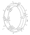
- FIG. 2 is an enlarged scale perspective view of the plug seat assembly in a diametrically compressed orientation
- FIG. 3 is an enlarged scale perspective view of the plug seat assembly in a diametrically expanded orientation
- FIG. 4 is an enlarged scale perspective view of a first alternative embodiment of the plug seat assembly in a diametrically compressed orientation
- FIG. 5 is an enlarged scale perspective view of a second alternative embodiment of the plug seat assembly in a diametrically expanded orientation
- FIG. 6 is a schematic, radially inwardly directed, partially phantomed elevational view of portions of a circumferentially adjacent segment pair of a third alternative embodiment of the plug seat assembly in a diametrically compressed orientation;
- FIG. 7 is a schematic, radially inwardly directed, partially phantomed elevational view of portions of a circumferentially adjacent segment pair of a fourth alternative embodiment of the plug seat assembly in a diametrically compressed orientation;
- FIG. 8 is a cross-sectional view through one of the FIG. 7 plug seat assembly segments taken along line 8 - 8 of FIG. 7 .
- FIG. 1 Cross-sectionally illustrated in FIG. 1 is a representative tubular downhole tool 10 centered about a longitudinal axis 12 and coaxially received in a tubing section 13 of a wellbore string.
- Tool 10 which, by way of non-limiting example, is a sliding sleeve valve, operatively and coaxially supports therein a first embodiment 14 of a specially designed annular, diametrically expandable plug seat assembly embodying principles of the present invention.
- plug seat assembly 14 includes a series of arcuate rigid peripheral circumferential segments 16 (representatively, but not by way of limitation, six in number) illustratively formed from a suitable metal material.
- each circumferentially adjacent pair of segments 16 circumferentially overlap each other at multifaceted juncture areas 18 (see FIGS. 1 and 2 ) which serve to prevent, by means of a rigid blocking action between each given segment 16 and the two segments 16 between which it is interposed, the axial separation in either direction of the given segment 16 from the balance of the plug seat 14 .
- Plug seat 14 when operatively supported in the tool 10 , is expandable from a FIG. 2 diametrically compressed orientation initially blocking a pre-selected plug ball (not shown) from passing therethrough, to a FIG. 3 diametrically expanded orientation in which the interior diameter of the plug seat 14 is increased (by fluid pressure on a plug ball landing on the seat) to an extent permitting the plug ball to pass through the plug seat 14 .
- the segments 16 circumferentially overlap one another in a manner preventing any of the segments 16 from being completely dislodged axially from the rest of the seat segments 16 .
- each of the rigid segments 16 has one end on which a generally V-shaped projection 20 is formed and has angled facet portions 22 , and an opposite end on which a generally V-shaped recess 24 is formed and has angled facet portions 26 .
- Each projection 20 is complementarily receivable in one of the recesses 24 in a manner such that with the plug seat 14 in its FIG. 2 diametrically compressed orientation, the facet pairs 22 of each segment 16 are slidingly and sealingly engaged with the facet pairs 26 of an adjacent segment 16 .
- the plug seat 14 when in its diametrically compressed orientation has conically tapered, oppositely sloped annular peripheral surfaces 28 , 30 respectively disposed on its top and bottom sides.
- the expandable plug seat 14 is coaxially sandwiched between (1) the conically tapered end surface 32 of a rigid tubular member 34 coaxially anchored, as by a threaded connection 36 , to a tubular sleeve 38 slidably received in the wellbore string tubular section 13 , and (2) the conically tapered end surface 40 of an axially shiftable tubing component 42 telescoped within the tubular sleeve 38 .
- the tapered top annular peripheral surface 28 of the expandable seat 14 is slidably and complementarily engaged by the conically tapered end surface 40
- the tapered bottom annular peripheral surface 30 of the expandable seat 14 is slidably and complementarily engaged by the conically tapered end surface 32 .
- an annular pocket area 44 is formed within the interior of the tool 10 and outwardly circumscribes the expandable seat 14 .
- annular pocket area 46 is formed within the tool 10 and receives an annular compression spring structure 48 that forcibly bears against axially opposing annular portions 50 , 52 of the tubular members 42 , 38 and resiliently biases the tubular member 42 in a downhole direction 54 .
- This causes the tapered peripheral surface areas 28 , 30 of the expandable seat 14 to be forcibly wedged between the tapered tubular member end surfaces 40 , 32 to thereby cammingly create around the periphery of the seat 14 a radially inwardly directed force that yieldingly urges the seat 14 toward its diametrically compressed orientation shown in FIGS. 1 and 2 .
- the spring 48 downwardly returns the upwardly displaced tubing component 42 to its FIG. 1 position to thereby cammingly drive the diametrically expanded seat 14 back to its diametrically compressed orientation shown in FIGS. 1 and 2 .
- the circumferentially overlapping of the individual seat segments 16 prevents axial separation of any of the segments 16 from the balance of the overall seat assembly 14 .
- the seat 14 is returned to its diametrically compressed orientation, the multifaceted segment ends re-seal at their juncture areas 18 .
- a first alternate embodiment 14 a of the previously described expandable plug seat 14 is perspectively illustrated in its diametrically compressed orientation in FIG. 4 .
- Expandable plug seat 14 a is identical to seat 14 with the exception that in the seat 14 a layers of a suitable elastomeric material 60 are bonded within the multifaceted juncture areas 18 a of the seat 14 a .
- Each elastomeric material layer 60 may be bonded to both of its two associated facing seat segment ends, or to only one of them.
- the use of the elastomeric material 60 desirably eliminates the necessity to precisely machine the segment end facets to achieve a fluid tight seal at the segment juncture areas when the seat assembly 14 a is in its diametrically compressed orientation.
- a second alternate embodiment 14 b of the previously described expandable plug seat 14 is perspectively illustrated in FIG. 5 in a diametrically expanded orientation which, for illustrative purposes, is of a larger diameter than would be momentarily created by a plug ball operatively passing therethrough in the tool 10 .
- components in the seat 14 similar to those in the seat 14 have been given identical reference numerals to which the subscript “a” have been appended.
- the seat segments 16 b of the expandable plug seat 14 b do not have zig-zagged multi-faceted “puzzle cut” opposite ends to create circumferential overlapping between adjacent segment ends.
- each seat segment 16 b lie in single, axially extending planes, with circularly cross-sectioned pin portions 66 projecting outwardly from the ends 62 and being complementarily and slidably receivable in corresponding circularly cross-sectioned holes 68 extending inwardly into the ends 64 .
- each planar segment end 62 c has two pins 66 c projecting therefrom and slidably received in two holes 68 c projecting into the end 64 c of an adjacent segment 62 c , thereby preventing rocking of any of the segments 16 c relative to the balance of the seat 14 c.
- FIG. 7 A schematically depicted portion of an alternate embodiment 14 d of the two segment pin seat embodiment 14 c is shown in FIG. 7 .
- components in the seat 14 d similar to those in the seat 14 c have been given identical reference numerals to which the subscript “d” have been appended.
- the seat 14 c circular holes 66 c and holes 68 c are replaced with a single, non-circularly cross-sectioned segment end pin 70 (representatively of a rectangular cross-section as shown in FIG. 8 ) which is slidably received in a complementarily configured segment end hole 72 to prevent undesired seat segment rocking.
Landscapes
- Life Sciences & Earth Sciences (AREA)
- Engineering & Computer Science (AREA)
- Geology (AREA)
- Mining & Mineral Resources (AREA)
- Physics & Mathematics (AREA)
- Environmental & Geological Engineering (AREA)
- Fluid Mechanics (AREA)
- General Life Sciences & Earth Sciences (AREA)
- Geochemistry & Mineralogy (AREA)
- Quick-Acting Or Multi-Walled Pipe Joints (AREA)
Abstract
Description
Claims (24)
Priority Applications (2)
| Application Number | Priority Date | Filing Date | Title |
|---|---|---|---|
| US14/134,089 US9506322B2 (en) | 2013-12-19 | 2013-12-19 | Downhole tool with expandable annular plug seat assembly having circumferentially overlapping seat segment joints |
| PCT/US2014/055483 WO2015094437A1 (en) | 2013-12-19 | 2014-09-12 | Expandable plug seat having circumferentially overlapping segments |
Applications Claiming Priority (1)
| Application Number | Priority Date | Filing Date | Title |
|---|---|---|---|
| US14/134,089 US9506322B2 (en) | 2013-12-19 | 2013-12-19 | Downhole tool with expandable annular plug seat assembly having circumferentially overlapping seat segment joints |
Publications (2)
| Publication Number | Publication Date |
|---|---|
| US20150176361A1 US20150176361A1 (en) | 2015-06-25 |
| US9506322B2 true US9506322B2 (en) | 2016-11-29 |
Family
ID=53399452
Family Applications (1)
| Application Number | Title | Priority Date | Filing Date |
|---|---|---|---|
| US14/134,089 Expired - Fee Related US9506322B2 (en) | 2013-12-19 | 2013-12-19 | Downhole tool with expandable annular plug seat assembly having circumferentially overlapping seat segment joints |
Country Status (2)
| Country | Link |
|---|---|
| US (1) | US9506322B2 (en) |
| WO (1) | WO2015094437A1 (en) |
Cited By (3)
| Publication number | Priority date | Publication date | Assignee | Title |
|---|---|---|---|---|
| US20180363406A1 (en) * | 2017-06-14 | 2018-12-20 | Baker Hughes Incorporated | Variable radius backup ring, downhole system, and method |
| US10411448B1 (en) * | 2018-08-20 | 2019-09-10 | Siemens Industry, Inc. | Ring assembly of radially-concentric rings with quick fastening mechanism to detachably connect such rings to one another |
| US11162322B2 (en) | 2018-04-05 | 2021-11-02 | Halliburton Energy Services, Inc. | Wellbore isolation device |
Families Citing this family (14)
| Publication number | Priority date | Publication date | Assignee | Title |
|---|---|---|---|---|
| US9353598B2 (en) * | 2012-05-09 | 2016-05-31 | Utex Industries, Inc. | Seat assembly with counter for isolating fracture zones in a well |
| US9556704B2 (en) | 2012-09-06 | 2017-01-31 | Utex Industries, Inc. | Expandable fracture plug seat apparatus |
| US9677380B2 (en) * | 2012-12-13 | 2017-06-13 | Weatherford Technology Holdings, Llc | Sliding sleeve having inverting ball seat |
| CN102979494B (en) * | 2012-12-28 | 2015-10-28 | 中国石油集团渤海钻探工程有限公司 | Pitching open-type many bunches of sliding sleeves |
| AU2014357648B2 (en) * | 2013-12-06 | 2019-02-07 | Schlumberger Technology B.V. | Deploying an expandable downhole seat assembly |
| US10801284B2 (en) * | 2015-12-23 | 2020-10-13 | Schlumberger Technology Corporation | Expanding and collapsing apparatus and methods of use |
| GB201522725D0 (en) * | 2015-12-23 | 2016-02-03 | Peak Well Systems Pty Ltd | Expanding and collapsing apparatus and methods of use |
| NO342306B1 (en) * | 2016-08-24 | 2018-05-07 | Frac Tech As | Pipe-mounted downhole activation system |
| CN107956450B (en) * | 2016-10-18 | 2020-09-22 | 中国石油化工股份有限公司 | Floating hoop |
| US10571027B2 (en) * | 2017-06-09 | 2020-02-25 | Gryphon Oilfield Solutions, Llc | Metal ring seal and improved profile selective system for downhole tools |
| US10520086B2 (en) | 2017-07-11 | 2019-12-31 | T-Lon Products, Inc. | Apparatus and systems for preventing extrusion |
| NO343864B1 (en) | 2018-04-25 | 2019-06-24 | Interwell Norway As | Well tool device for opening and closing a fluid bore in a well |
| US11066894B2 (en) * | 2019-06-04 | 2021-07-20 | Baker Hughes Oilfield Operations Llc | Spring loaded inner diameter opening ball seat |
| US20240011369A1 (en) * | 2022-07-07 | 2024-01-11 | Halliburton Energy Services, Inc. | Shifting sleeve operated with plug against two or more plug seats |
Citations (9)
| Publication number | Priority date | Publication date | Assignee | Title |
|---|---|---|---|---|
| US4324438A (en) | 1980-11-13 | 1982-04-13 | Eagle-Picher Industries, Inc. | Drilling deck bushing |
| US20020043368A1 (en) | 2000-10-12 | 2002-04-18 | Greene, Tweed Of Delaware, Inc. | Anti-extrusion device for downhole applications |
| US20070131413A1 (en) | 2005-12-07 | 2007-06-14 | Francois Millet | Mandrel for introduction into a fluid circulation duct, and related production well |
| US7243731B2 (en) | 2001-08-20 | 2007-07-17 | Enventure Global Technology | Apparatus for radially expanding tubular members including a segmented expansion cone |
| US20110048744A1 (en) | 2009-08-27 | 2011-03-03 | Baker Hughes Incorporated | Expandable Gage Ring |
| US20120227973A1 (en) | 2010-06-29 | 2012-09-13 | Baker Hughes Incorporated | Tool with Multisize Segmented Ring Seat |
| US20120305236A1 (en) | 2011-06-01 | 2012-12-06 | Varun Gouthaman | Downhole tools having radially expandable seat member |
| US20130118732A1 (en) * | 2011-03-02 | 2013-05-16 | Team Oil Tools, Lp | Multi-actuating seat and drop element |
| US20130299199A1 (en) | 2012-05-09 | 2013-11-14 | Utex Industries, Inc. | Seat assembly with counter for isolating fracture zones in a well |
-
2013
- 2013-12-19 US US14/134,089 patent/US9506322B2/en not_active Expired - Fee Related
-
2014
- 2014-09-12 WO PCT/US2014/055483 patent/WO2015094437A1/en not_active Ceased
Patent Citations (9)
| Publication number | Priority date | Publication date | Assignee | Title |
|---|---|---|---|---|
| US4324438A (en) | 1980-11-13 | 1982-04-13 | Eagle-Picher Industries, Inc. | Drilling deck bushing |
| US20020043368A1 (en) | 2000-10-12 | 2002-04-18 | Greene, Tweed Of Delaware, Inc. | Anti-extrusion device for downhole applications |
| US7243731B2 (en) | 2001-08-20 | 2007-07-17 | Enventure Global Technology | Apparatus for radially expanding tubular members including a segmented expansion cone |
| US20070131413A1 (en) | 2005-12-07 | 2007-06-14 | Francois Millet | Mandrel for introduction into a fluid circulation duct, and related production well |
| US20110048744A1 (en) | 2009-08-27 | 2011-03-03 | Baker Hughes Incorporated | Expandable Gage Ring |
| US20120227973A1 (en) | 2010-06-29 | 2012-09-13 | Baker Hughes Incorporated | Tool with Multisize Segmented Ring Seat |
| US20130118732A1 (en) * | 2011-03-02 | 2013-05-16 | Team Oil Tools, Lp | Multi-actuating seat and drop element |
| US20120305236A1 (en) | 2011-06-01 | 2012-12-06 | Varun Gouthaman | Downhole tools having radially expandable seat member |
| US20130299199A1 (en) | 2012-05-09 | 2013-11-14 | Utex Industries, Inc. | Seat assembly with counter for isolating fracture zones in a well |
Non-Patent Citations (1)
| Title |
|---|
| International Search Report and Written Opinion issued for PCT/US2014/055483 dated Dec. 16, 2014, 10 pgs. |
Cited By (4)
| Publication number | Priority date | Publication date | Assignee | Title |
|---|---|---|---|---|
| US20180363406A1 (en) * | 2017-06-14 | 2018-12-20 | Baker Hughes Incorporated | Variable radius backup ring, downhole system, and method |
| US10760369B2 (en) * | 2017-06-14 | 2020-09-01 | Baker Hughes, A Ge Company, Llc | Variable radius backup ring for a downhole system |
| US11162322B2 (en) | 2018-04-05 | 2021-11-02 | Halliburton Energy Services, Inc. | Wellbore isolation device |
| US10411448B1 (en) * | 2018-08-20 | 2019-09-10 | Siemens Industry, Inc. | Ring assembly of radially-concentric rings with quick fastening mechanism to detachably connect such rings to one another |
Also Published As
| Publication number | Publication date |
|---|---|
| US20150176361A1 (en) | 2015-06-25 |
| WO2015094437A1 (en) | 2015-06-25 |
Similar Documents
| Publication | Publication Date | Title |
|---|---|---|
| US9506322B2 (en) | Downhole tool with expandable annular plug seat assembly having circumferentially overlapping seat segment joints | |
| US9926746B2 (en) | Actuating a downhole tool | |
| US8887811B2 (en) | Downhole tool with expandable seat | |
| US9556704B2 (en) | Expandable fracture plug seat apparatus | |
| CA2567632C (en) | Downhole isolation tool | |
| US10597974B2 (en) | Downhole valve apparatus | |
| US20160319619A1 (en) | Extended duration section mill and methods of use | |
| US20100116503A1 (en) | Dual check valve | |
| US20140345949A1 (en) | Seal system for downhole tool | |
| US20180010697A1 (en) | Gate valve and seats for a gate valve | |
| US20230111681A1 (en) | Check valve assembly | |
| US20190017610A1 (en) | Gate valve and seat insert for a gate valve | |
| CA2978804A1 (en) | Hydraulic pulse valve with improved wear life and performance | |
| US10533388B2 (en) | Flow diverter | |
| US10584558B2 (en) | Downhole packer tool | |
| US20150308229A1 (en) | Downhole Apparatus and Method | |
| US9863223B2 (en) | Plunger assembly with dual dart system | |
| US20120061094A1 (en) | Ball-seat apparatus and method | |
| US11459839B2 (en) | Sleeve for downhole tools | |
| GB2583156A (en) | Flow diverter valve |
Legal Events
| Date | Code | Title | Description |
|---|---|---|---|
| AS | Assignment |
Owner name: UTEX INDUSTRIES, INC., TEXAS Free format text: ASSIGNMENT OF ASSIGNORS INTEREST;ASSIGNORS:PROSSER, PATRICK LAWRENCE;CARTER, DEREK L.;NAEDLER, MARK H.;SIGNING DATES FROM 20140220 TO 20140304;REEL/FRAME:032645/0087 |
|
| ZAAA | Notice of allowance and fees due |
Free format text: ORIGINAL CODE: NOA |
|
| ZAAB | Notice of allowance mailed |
Free format text: ORIGINAL CODE: MN/=. |
|
| STCF | Information on status: patent grant |
Free format text: PATENTED CASE |
|
| MAFP | Maintenance fee payment |
Free format text: PAYMENT OF MAINTENANCE FEE, 4TH YEAR, LARGE ENTITY (ORIGINAL EVENT CODE: M1551); ENTITY STATUS OF PATENT OWNER: LARGE ENTITY Year of fee payment: 4 |
|
| AS | Assignment |
Owner name: BANK OF AMERICA, N.A., NORTH CAROLINA Free format text: SECOND LIEN PATENT SHORT FORM SECURITY AGREEMENT;ASSIGNOR:UTEX INDUSTRIES, INC.;REEL/FRAME:052706/0766 Effective date: 20200515 Owner name: BANK OF AMERICA, N.A., NORTH CAROLINA Free format text: FIRST LIEN PATENT SHORT FORM SECURITY AGREEMENT;ASSIGNOR:UTEX INDUSTRIES, INC.;REEL/FRAME:052707/0740 Effective date: 20200515 |
|
| AS | Assignment |
Owner name: UMB BANK, N.A., AS SUCCESSOR COLLATERAL AGENT, MISSOURI Free format text: ASSIGNMENT AND ASSUMPTION OF SECOND LIEN PATENT SHORT FORM SECURITY AGREEMENT;ASSIGNOR:BANK OF AMERICA, N.A., AS RESIGNING COLLATERAL AGENT;REEL/FRAME:052908/0880 Effective date: 20200605 |
|
| AS | Assignment |
Owner name: ALTER DOMUS (US) LLC, AS COLLATERAL AGENT, ILLINOIS Free format text: SECURITY INTEREST;ASSIGNOR:UTEX INDUSTRIES, INC.;REEL/FRAME:054630/0714 Effective date: 20201203 Owner name: DURAQUEST, INC., TEXAS Free format text: RELEASE BY SECURED PARTY;ASSIGNOR:BANK OF AMERICA, N.A., AS COLLATERAL AGENT;REEL/FRAME:054634/0497 Effective date: 20201203 Owner name: UTEX INDUSTRIES, INC., TEXAS Free format text: RELEASE BY SECURED PARTY;ASSIGNOR:UMB BANK, N.A., AS SUCCESSOR COLLATERAL AGENT;REEL/FRAME:054634/0484 Effective date: 20201203 Owner name: UTEX INDUSTRIES, INC., TEXAS Free format text: RELEASE BY SECURED PARTY;ASSIGNOR:BANK OF AMERICA, N.A., AS COLLATERAL AGENT;REEL/FRAME:054634/0497 Effective date: 20201203 Owner name: DURAQUEST, INC., TEXAS Free format text: RELEASE BY SECURED PARTY;ASSIGNOR:UMB BANK, N.A., AS SUCCESSOR COLLATERAL AGENT;REEL/FRAME:054634/0484 Effective date: 20201203 |
|
| AS | Assignment |
Owner name: MIDCAP FINANCIAL TRUST, AS AGENT, MARYLAND Free format text: SECURITY INTEREST;ASSIGNOR:UTEX INDUSTRIES, INC.;REEL/FRAME:055101/0383 Effective date: 20210129 |
|
| AS | Assignment |
Owner name: MIDCAP FUNDING IV TRUST, MARYLAND Free format text: REAFFIRMATION AGREEMENT;ASSIGNORS:UTEX INDUSTRIES, INC.;UTEX INDUSTRIES HOLDINGS, LLC;REEL/FRAME:059289/0107 Effective date: 20220225 |
|
| AS | Assignment |
Owner name: UTEX INDUSTRIES, INC., TEXAS Free format text: RELEASE BY SECURED PARTY;ASSIGNOR:ALTER DOMUS (US) LLC, AS COLLATERAL AGENT;REEL/FRAME:059242/0117 Effective date: 20220225 |
|
| FEPP | Fee payment procedure |
Free format text: MAINTENANCE FEE REMINDER MAILED (ORIGINAL EVENT CODE: REM.); ENTITY STATUS OF PATENT OWNER: LARGE ENTITY |
|
| LAPS | Lapse for failure to pay maintenance fees |
Free format text: PATENT EXPIRED FOR FAILURE TO PAY MAINTENANCE FEES (ORIGINAL EVENT CODE: EXP.); ENTITY STATUS OF PATENT OWNER: LARGE ENTITY |
|
| STCH | Information on status: patent discontinuation |
Free format text: PATENT EXPIRED DUE TO NONPAYMENT OF MAINTENANCE FEES UNDER 37 CFR 1.362 |
|
| FP | Lapsed due to failure to pay maintenance fee |
Effective date: 20241129 |
|
| AS | Assignment |
Owner name: UTEX INDUSTRIES, INC., TEXAS Free format text: RELEASE BY SECURED PARTY;ASSIGNOR:MIDCAP FUNDING IV TRUST;REEL/FRAME:070415/0460 Effective date: 20250227 |