US9503314B2 - Wireless transmission device, failure-information forwarding method, and failure-information notification method - Google Patents
Wireless transmission device, failure-information forwarding method, and failure-information notification method Download PDFInfo
- Publication number
- US9503314B2 US9503314B2 US14/356,373 US201214356373A US9503314B2 US 9503314 B2 US9503314 B2 US 9503314B2 US 201214356373 A US201214356373 A US 201214356373A US 9503314 B2 US9503314 B2 US 9503314B2
- Authority
- US
- United States
- Prior art keywords
- wireless
- wireless transmission
- failure
- transmission device
- information
- Prior art date
- Legal status (The legal status is an assumption and is not a legal conclusion. Google has not performed a legal analysis and makes no representation as to the accuracy of the status listed.)
- Expired - Fee Related, expires
Links
- 230000005540 biological transmission Effects 0.000 title claims abstract description 623
- 238000000034 method Methods 0.000 title claims description 39
- 238000010586 diagram Methods 0.000 description 26
- 230000014759 maintenance of location Effects 0.000 description 25
- 238000000605 extraction Methods 0.000 description 17
- 238000006243 chemical reaction Methods 0.000 description 15
- 230000008569 process Effects 0.000 description 9
- 230000000875 corresponding effect Effects 0.000 description 7
- 108010076504 Protein Sorting Signals Proteins 0.000 description 5
- 239000008186 active pharmaceutical agent Substances 0.000 description 5
- 230000000694 effects Effects 0.000 description 4
- 239000000284 extract Substances 0.000 description 4
- 230000002159 abnormal effect Effects 0.000 description 3
- 230000002596 correlated effect Effects 0.000 description 3
- 230000008901 benefit Effects 0.000 description 1
- 238000001514 detection method Methods 0.000 description 1
- 230000007246 mechanism Effects 0.000 description 1
- 230000006855 networking Effects 0.000 description 1
- 230000002250 progressing effect Effects 0.000 description 1
- 230000000717 retained effect Effects 0.000 description 1
- 230000007704 transition Effects 0.000 description 1
Images


Classifications
-
- H—ELECTRICITY
- H04—ELECTRIC COMMUNICATION TECHNIQUE
- H04L—TRANSMISSION OF DIGITAL INFORMATION, e.g. TELEGRAPHIC COMMUNICATION
- H04L41/00—Arrangements for maintenance, administration or management of data switching networks, e.g. of packet switching networks
- H04L41/06—Management of faults, events, alarms or notifications
-
- H—ELECTRICITY
- H04—ELECTRIC COMMUNICATION TECHNIQUE
- H04L—TRANSMISSION OF DIGITAL INFORMATION, e.g. TELEGRAPHIC COMMUNICATION
- H04L43/00—Arrangements for monitoring or testing data switching networks
- H04L43/08—Monitoring or testing based on specific metrics, e.g. QoS, energy consumption or environmental parameters
- H04L43/0805—Monitoring or testing based on specific metrics, e.g. QoS, energy consumption or environmental parameters by checking availability
- H04L43/0811—Monitoring or testing based on specific metrics, e.g. QoS, energy consumption or environmental parameters by checking availability by checking connectivity
-
- H—ELECTRICITY
- H04—ELECTRIC COMMUNICATION TECHNIQUE
- H04L—TRANSMISSION OF DIGITAL INFORMATION, e.g. TELEGRAPHIC COMMUNICATION
- H04L69/00—Network arrangements, protocols or services independent of the application payload and not provided for in the other groups of this subclass
- H04L69/14—Multichannel or multilink protocols
-
- H—ELECTRICITY
- H04—ELECTRIC COMMUNICATION TECHNIQUE
- H04L—TRANSMISSION OF DIGITAL INFORMATION, e.g. TELEGRAPHIC COMMUNICATION
- H04L69/00—Network arrangements, protocols or services independent of the application payload and not provided for in the other groups of this subclass
- H04L69/40—Network arrangements, protocols or services independent of the application payload and not provided for in the other groups of this subclass for recovering from a failure of a protocol instance or entity, e.g. service redundancy protocols, protocol state redundancy or protocol service redirection
-
- H—ELECTRICITY
- H04—ELECTRIC COMMUNICATION TECHNIQUE
- H04W—WIRELESS COMMUNICATION NETWORKS
- H04W24/00—Supervisory, monitoring or testing arrangements
- H04W24/04—Arrangements for maintaining operational condition
Definitions
- the present invention relates to a technique for notifying of a failure between a plurality of wireless transmission devices that are connected so as to be capable of communicating.
- LAN local area network
- a transmission device that is connected to a network device via a wired transmission channel transmits a LAN signal from the network device to an opposite opposing transmission device via a wireless transmission channel.
- the opposing transmission device outputs the signal received via the wireless transmission channel to the network device, which is connected to the opposing transmission device itself via the wired transmission channel.
- Patent Document 1 discloses a method outlined below. That is to say, when a transmission device connected to the above system via the wireless transmission channel detects a failure in the transmission channel (the wired transmission channel and the wireless transmission channel connected to the transmission device), the network device connected to the station itself via the wired transmission channel is notified of the failure. Furthermore, the network device connected to the opposing transmission device via the wired transmission channel is also notified.
- the transmission device cuts the wired transmission channel line connected to the transmission device when a failure in the transmission channel is detected. Furthermore, it converts a control signal sequence for notifying a failure into a data sequence and outputs the signal to the wireless transmission channel to thereby transmit the control signal sequence to the opposing transmission device. Moreover, the transmission device cuts the wired transmission channel of the station itself also when the control signal sequence is received from the opposing transmission device.
- the transmission device is capable of notifying a network device connected to the station itself of a failure when the transmission device detects a failure in the transmission channel. Furthermore, it is capable of notifying the network device connected to the station itself of a failure also when the opposing transmission device detects a failure in the transmission channel.
- the transmission device In recent years, transition to IP (Internet protocol) is progressing in networking.
- IP Internet protocol
- the transmission device In systems such as the one mentioned above, the transmission device often houses a plurality of wired transmission channels and includes a switching function.
- Patent Document 1 discloses a method in which also in a system with each transmission device housing a plurality of wired transmission channels therein, a failure is notified to each network device connected to the station itself and to each network device connected to the opposing station (FIG. 8 and paragraphs [0076] and [0077] in Patent Document 1).
- each transmission device includes, for each of the plurality of wired transmission channels of the station itself, a function of detecting a failure in the wired transmission channel, a function of detecting a failure in the wireless transmission channel, and a function of outputting the control signal sequence mentioned above to the wireless transmission channel when a failure is detected.
- Each transmission device cuts the wired transmission channel when a failure is detected and when the control signal sequence is received from the opposing transmission device.
- the transmission device is capable of notifying a network device connected to the station itself of a failure when the station itself detects a failure in the transmission channel. Furthermore, it is capable of notifying the network device connected to the station itself of a failure also when the opposing transmission device detects a failure in the transmission channel.
- the method mentioned above is considered not limited to only being applied to a system that uses a wireless transmission channel in part of the transmission channel. That is to say, the method mentioned above is considered to be able to be applied also to a system in which transmission devices connected via a transmission channel (that corresponds to the above wireless transmission channel) between the transmission devices (that correspond to the above transmission devices) transmit signals of the plurality of wired transmission channels connected to the respective transmission devices.
- An exemplary object of the present invention is to provide a technique that enables notification of a failure between transmission devices connected to each other via wireless transmission channels.
- a wireless transmission device houses a plurality of wireless transmission channels including a first and a second wireless transmission channel.
- the wireless transmission device includes: a wireless signal transmitting and receiving unit that includes a first wireless port and a second port, the first wireless port transmitting and receiving a wireless signal to and from a first transmission device via the first wireless transmission channel, the second wireless port transmitting and receiving a wireless signal to and from a second transmission device via the second wireless transmission channel; and a control unit that notifies the second transmission device of a failure via the second wireless transmission channel in a case where a failure relating to the first wireless port arises.
- a failure information forwarding method is for a wireless transmission device transmitting and receiving a wireless signal to and from a first transmission device via a first wireless transmission channel, and transmitting and receiving a wireless signal to and from a second transmission device via a second wireless transmission channel.
- the failure information forwarding method includes: receiving failure information from the first transmission device via the first wireless transmission channel; and forwarding the failure information to the second transmission device via the second wireless transmission channel upon receiving the failure information.
- a failure information notification method notifies of failure information from a first wireless transmission device connected to a plurality of wired transmission channels and a plurality of wireless transmission channels, the first wireless transmission device performing wireless communication via the plurality of wired transmission channels.
- the failure information notification method includes: detecting a failure in a signal received from each of the plurality of wired transmission channels and the plurality of wireless transmission channels; and notifying a second wireless transmission device of information via a wireless transmission channel upon detecting a failure in any one of the plurality of wired transmission channels and the plurality of wireless transmission channels, the information being related to the failure, the wireless transmission channel being one of the plurality of wireless transmission channels in which no failure is detected.
- the second transmission device in a system in which a first transmission device and a second transmission device are connected via wireless transmission channels to a transmission device capable of housing a plurality of wireless transmission channels, the second transmission device can be notified of a failure detected by the first transmission device.
- FIG. 1 is a system configuration diagram showing a system configuration of a transmission system according to an exemplary embodiment of the present invention.
- FIG. 2 is a schematic block diagram showing a function configuration of a transmission device shown in FIG. 1 .
- FIG. 3 is a schematic block diagram showing a function configuration of a control unit shown in FIG. 2 .
- FIG. 4 is a diagram showing an overview of a transmission system in a first application example according to the exemplary embodiment of the present invention.
- FIG. 5 is a diagram showing an overview of a transmission system in a second application example according to the exemplary embodiment.
- FIG. 6 is a diagram showing an overview of a transmission system in a third application example according to the exemplary embodiment.
- FIG. 7 is a diagram showing an overview of a transmission system in a fourth application example according to the exemplary embodiment.
- FIG. 8 is a diagram showing an overview of a transmission system in a fifth application example according to the exemplary embodiment.
- FIG. 9 is a diagram showing an overview of a transmission system in a sixth application example according to the exemplary embodiment.
- FIG. 10 is a sequence diagram showing a specific example of an operation flow of the transmission system according to the exemplary embodiment.
- FIG. 11 is a sequence diagram showing a specific example of an operation flow of the transmission system according to the exemplary embodiment.
- FIG. 12 is a diagram for describing an effect of the exemplary embodiment.
- FIG. 13 is a diagram showing an overview of a modified example of a transmission system according to the exemplary embodiment.
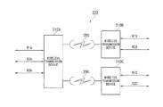
- FIG. 1 is a system configuration diagram showing a system configuration of a transmission system 200 according to an exemplary embodiment of the present invention.
- the transmission system 200 includes a plurality of wireless transmission devices.
- the transmission system 200 includes three wireless transmission devices 210 ( 210 A, 210 B, 210 C).
- the wireless transmission device 210 A is connected to one or more (three in the example of FIG. 1 ) wired transmission channels R 1 A, R 2 A, and R 3 A.
- the wireless transmission device 210 B is connected to one or more (two in the example of FIG. 1 ) wired transmission channels R 1 B and R 2 B.
- the wireless transmission device 210 C is connected to one or more (two in the example of FIG. 1 ) wired transmission channels R 1 C and R 2 C.
- the wireless transmission device 210 A and the wireless transmission device 210 B are opposed to each other and are connected to each other by a wireless transmission channel 280 .
- the wireless transmission device 210 A and the wireless transmission device 210 C are opposingly connected to each other by a wireless transmission channel 290 .
- Each wired transmission channel is connected to a LAN (local area network) device (network device) not shown in the figure such as a hub, a switching hub, a router, and a computer terminal.
- LAN local area network
- the wireless transmission device 210 A converts LAN data from a network device (not shown in the figure) connected via the wired transmission channels R 1 A, R 2 A, and R 3 A, into a wireless signal.
- the wireless transmission device 210 A outputs the wireless signal to wireless transmission channels 280 and 290 , and transmits it to each of the wireless transmission device 210 B and the wireless transmission device 210 C.
- the wireless transmission device 210 B converts the wireless signal transmitted from the wireless transmission device 210 A via the wireless transmission channel 280 into LAN data.
- the wireless transmission device 210 B outputs the LAN data to a wired transmission channel, which corresponds to a transmission destination, among the wired transmission channels R 1 B and R 2 B, and transmits it to a network device connected to the wired transmission channel.
- the wireless transmission device 210 C converts the wireless signal transmitted from the wireless transmission device 210 A via the wireless transmission channel 290 into LAN data.
- the wireless transmission device 210 C outputs the LAN data to a wired transmission channel, which corresponds to a transmission destination, among the wired transmission channels R 1 C and R 2 C, and transmits it to a network device connected to the wired transmission channel.
- the wireless transmission device 210 A transmits the wireless signal transmitted from the wireless transmission device 210 B (wireless transmission device 210 C) directly to the other wireless transmission device 210 C (wireless transmission device 210 B). Moreover, if necessary, as described later, the wireless transmission device 210 A converts the wireless signal transmitted from the wireless transmission device 210 B (wireless transmission device 210 C) into LAN data and transmits it to the wired transmission channel R 1 A (R 2 A, R 3 A).
- the wireless transmission device 210 B converts LAN data from a network device connected via the wired transmission channel R 1 B or R 2 B, into a wireless signal.
- the wireless transmission device 210 B outputs the wireless signal to the wireless transmission channel 280 and transmits it to the transmission device 210 A.
- the wireless transmission device 210 A converts the wireless signal transmitted from the wireless transmission device 210 B via the wireless transmission channel 280 , into LAN data.
- the wireless transmission device 210 A outputs the LAN data to a wired transmission channel, which corresponds to a transmission destination, among the wired transmission channels R 1 A, R 2 A, and R 3 A, and transmits it to a network device connected to the wired transmission channel.
- the wireless transmission device 210 A transmits the wireless signal as it is to the wireless transmission device 210 C via the other wireless transmission channel 290 .
- the wireless transmission device 210 C converts LAN data from a network device connected via the wired transmission channel R 1 C or R 2 C, into a wireless signal.
- the wireless transmission device 210 C outputs the wireless signal to the wireless transmission channel 290 and transmits it to the transmission device 210 A.
- the wireless transmission device 210 A converts the wireless signal transmitted from the wireless transmission device 210 C via the wireless transmission channel 290 , into LAN data.
- the wireless transmission device 210 A outputs the LAN data to a wired transmission channel, which corresponds to a transmission destination, among the wired transmission channels R 1 A, R 2 A, and R 3 A, and transmits it to a network device connected to the wired transmission channel.
- the wireless transmission device 210 A transmits the wireless signal as it is to the wireless transmission device 210 B via the other wireless transmission channel 280 .
- the wireless transmission devices 210 ( 210 A through 210 C) detect a failure in the wired transmission channels or wireless transmission channels connected to the wireless transmission devices themselves. When a failure is detected, the wireless transmission devices 210 cut wired transmission channels and perform failure notification to opposing wireless transmission devices.
- the wireless transmission devices 210 When a failure notification is received from an opposing wireless transmission device, the wireless transmission devices 210 cut the wired transmission channel connected thereto, and perform failure notification to opposing wireless transmission devices that have not received the failure.
- the wireless transmission device 210 A, the wireless transmission device 210 B, and the wireless transmission device 210 C respectively have a similar configuration. Accordingly, the wireless transmission devices 210 are described in detail, taking the wireless transmission device 210 A as an example.
- LAN received data is referred to as “LAN reception data DLS”.
- FIG. 2 is a schematic block diagram showing a function configuration of the transmission device 210 A.
- the transmission device 210 A includes a LAN signal termination unit 220 , a signal conversion unit 230 , a signal reproduction unit 240 , an opposing device group information extraction unit 250 , an opposing device link cut information extraction unit 260 , a wireless signal transmitting and receiving unit 270 , and a control unit 300 .
- the LAN signal termination unit 220 transmits/receives a LAN signal (LAN data signal) via the wired transmission channels R 1 A, R 2 A, and R 3 A, and establishes a link on a data link layer between itself and network devices.
- the LAN signal termination unit 220 receives LAN data from a network device via a wired transmission channel with an established link, and transmits LAN reception data DLS to the signal conversion unit 230 .
- the LAN signal termination unit 220 stores wired state information.
- the wired state information indicates, for each wired transmission channel, whether the wired transmission channel is in a state of being used or in a state of not being used in the device itself (wireless transmission device 210 A).
- the administrator (user) of the transmission system 200 can arbitrarily set wired state information of each wired transmission channel (wired port) on the wireless transmission device 210 A side, to the “used” state or “not used” state. In the figure, information set by the administrator is referred to as “user setting”.
- the LAN signal termination unit 220 outputs LAN port information LP, which indicates either “used” or “not used” wired state information set for each wired transmission channel, to the control unit 300 . In the following description, there is described a case where all of 210 A side wired transmission channels (R 1 A, R 2 A, and R 3 A) are set to “used”.
- the LAN signal termination unit 220 monitors the failure state of the wired transmission channels. For the wired transmission channel (R 1 A through R 3 A) in which a failure has occurred, the LAN signal termination unit 220 outputs to the control unit 300 failure information LS that indicates a failure has occurred.
- a state where “a failure has occurred in a wired transmission channel” is, for example, a state described below.
- a first example of this state is a state where no link has been established with a network device connected to the wired transmission channel although it is set to “used” state.
- a second example of this state is a state where the LAN data received via the wired transmission channel is abnormal data although it is set to “used” state”.
- the state where “a failure has occurred in a wired transmission channel” may also be another abnormal state.
- the LAN signal termination unit 220 receives LAN transmission data DLR from the signal reproduction unit 240 .
- the LAN signal termination unit 220 transmits the LAN transmission data DLR to a network device via a wired transmission channel with an established link.
- the LAN signal termination unit 220 monitors a link cut control signal CTR, which is described later, output from the control unit 300 . While a link cut control signal CTR is being detected, the LAN signal termination unit 220 cuts the wired transmission channel indicated by the link cut control signal CTR. “Cutting a wired transmission channel” means the LAN signal termination unit 220 cutting the link with the network device connected to the wired transmission channel.
- the signal conversion unit 230 multiplexes the LAN reception data DLS received from the LAN signal termination unit 220 , and self device group information SR and link cut information SRC received from the control unit 300 , and generates transmission data DS.
- the signal conversion unit 230 outputs the generated transmission data DS to the wireless signal transmitting and receiving unit 270 .
- the signal reproduction unit 240 receives reception data DR from the wireless signal transmitting and receiving unit 270 , and extracts a LAN signal from the reception data DR. The signal reproduction unit 240 then converts the extracted LAN signal into LAN transmission data DLR and outputs it to the LAN signal termination unit 220 . As described later, the reception data DR is the data that is received by another wireless transmission device 210 ( 210 B or 210 C), and that is received by the wireless signal transmitting and receiving unit 270 .
- the opposing device group information extraction unit 250 receives the reception data DR from the wireless signal transmitting and receiving unit 270 , and extracts from the reception data DR, group information TR of the wireless transmission device ( 210 B or 210 C) of the transmission source.
- the opposing device group information extraction unit 250 outputs the extracted group information TR to the control unit 300 .
- the group information TR of the wireless transmission device 210 B ( 210 C) is self device group information SR for the transmission device 210 B ( 210 C).
- Group information TR is referred to as “opposing device group information TR” in order to distinguish the self device group information SR of the wireless transmission device 210 A from the group information TR.
- the opposing device link cut information extraction unit 260 receives the reception data DR from the wireless signal transmitting and receiving unit 270 , and extracts from the reception data DR, link cut information TRC of the wireless transmission device ( 210 B or 210 C) of the transmission source.
- the opposing device link cut information extraction unit 260 outputs the extracted link cut information TRC to the control unit 300 .
- link cut information SRC of the self device wireless transmission device 210 A
- link cut information of the wireless transmission device 210 B ( 210 C) link cut information (link cut information extracted from the reception data DR) TRC on the transmission device 210 B side is referred to as “opposing device link cut information TRC”.
- the wireless signal transmitting and receiving unit 270 includes a wireless port for each wireless transmission channel.
- the wireless signal transmitting and receiving unit 270 includes wireless ports P 1 and P 2 respectively for the wireless transmission channel 280 and the wireless transmission channel 290 .
- the wireless signal transmitting and receiving unit 270 converts transmission data DS transmitted from the signal conversion unit 230 into a wireless signal.
- the wireless ports P 1 and P 2 of the wireless signal transmitting and receiving unit 270 output the wireless signal respectively to the wireless transmission device 210 B and the wireless transmission device 210 C via the wireless transmission channel 280 and the wireless transmission channel 290 .
- the wireless ports P 1 and P 2 of the wireless signal transmitting and receiving unit 270 receive the wireless signal from the wireless transmission device 210 B and the wireless transmission device 210 C via the wireless transmission channel 280 and the wireless transmission channel 290 .
- the wireless signal receiving unit 270 outputs the received wireless signal as reception data DR to the signal reproduction unit 240 , the opposing device group information extraction unit 250 , and the opposing device link cut information extraction unit 260 .
- the wireless signal transmitting and receiving unit 270 stores wireless state information.
- the wireless state information indicates, for each wireless transmission channel, whether the wireless transmission channel is in a state of being used or in a state of not being used in the device itself (wireless transmission device 210 A).
- the administrator of the transmission system 200 can arbitrarily set wireless state information of each wireless transmission channel (wireless port), to the “used” state or “not used” state.
- the wireless signal transmitting and receiving unit 270 outputs wireless port information MP, which indicates either “used” or “not used” wireless state information set for each wireless transmission channel, to the control unit 300 . In the following description, there is described a case where all of the wireless transmission channels ( 280 and 290 ) are set to “used”.
- the wireless signal transmitting and receiving unit 270 monitors the failure state of the wireless transmission channels. When a failure occurs, the wireless signal transmitting and receiving unit 270 generates wireless section failure information MS and outputs it to the control unit 300 . Examples of the state where “a failure has occurred in the wireless transmission channel 280 ( 290 )” include a state where the wireless transmission channel 280 ( 290 ) is cut, and a state where the wireless signal received from the wireless transmission channel 280 ( 290 ) is abnormal.
- the control unit 300 receives LAN port information LP and failure information LS from the LAN signal termination unit 220 .
- the control unit 300 receives from the wireless signal transmitting and receiving unit 270 the wireless port information MP and the wireless section failure information MS.
- the control unit 300 receives from the opposing device group information extraction unit 250 the opposing device group information TR.
- the control unit 300 receives from the opposing device link cut information extraction unit 260 the opposing device link cut information TRC.
- the control unit 300 outputs to the signal conversion unit 230 the self device group information SR and the link cut information SRC.
- the control unit 300 outputs to the LAN signal termination unit 220 a link cut control signal CTR.
- FIG. 3 is a schematic block diagram showing a function configuration of the control unit 300 .
- the control unit 300 includes a self device group information retention unit 310 , an inter-device group information retention unit 320 , a link cut information transmitting unit 330 , a link control unit 340 , and a wireless port priority retention unit 350 .
- the self device group information retention unit 310 receives input of LAN port information LP and prioritized wireless port information AMP.
- the self device group information retention unit 310 generates self device group information SR based on the LAN port information LP and the prioritized wireless port information AMP.
- the self device group information retention unit 310 retains the generated self device group information SR.
- the self device group information SR indicates corresponding relationships between the wired transmission channels (R 1 A, R 2 A, and R 3 A) and the wireless transmission channels ( 280 and 290 ) in the “used” state that are connected to the self device (wireless transmission device 210 A), and the link groups to which the wired transmission channels and the wireless transmission channels belong.
- a single link group is configured in combination with a wired transmission channel or a wireless transmission channel in the “used” state that is connected to the self device (wireless transmission device 210 A).
- a single wired transmission channel (wired port) belongs to a single link group.
- a single wireless transmission channel (wireless port) may belong to a plurality of link groups.
- This self device group information SR can be arbitrarily set by the administrator.
- the self device group information retention unit 310 generates self device group information SR based on the LAN port information LP, the prioritized wireless port information AMP, and the setting performed by the administrator, and retains it.
- the self device group information retention unit 310 outputs the retained self device group information SR to the inter-device group information retention unit 320 and the signal conversion unit 230 .
- the inter-device group information retention unit 320 receives an input of the opposing device group information TR from the opposing device group information extraction unit 250 .
- the inter-device group information retention unit 320 receives an input of the self device group information SR from the self device group information retention unit 310 .
- the inter-device group information retention unit 320 generates inter-device group information SB based on the opposing device group information TR and the self device group information SR.
- the inter-device group information retention unit 320 retains the generated inter-device group information SB.
- the inter-device group information retention unit 320 outputs the inter-device group information SB to the link cut information transmitting unit 330 and the link control unit 340 .
- the inter-device group information SB indicates a corresponding relationship between the link group indicated by the self device group information SR and each link group indicated by the opposing device group information TR.
- the inter-device group information retention unit 320 generates the inter-device group information SB according to the setting of the administrator.
- the link cut information transmitting unit 330 generates link cut information SRC based on the failure information of the wired transmission channel in the “used” state on the self device (wireless transmission device 210 A) side, and the failure information of the opposing device received from the opposing device.
- the link cut information transmitting unit 330 outputs the generated link cut information SRC to the signal conversion unit 230 .
- the link cut information SRC is then transmitted by the signal conversion unit 230 and the wireless signal transmitting and receiving unit 270 to the wireless transmission device 210 B ( 210 C) via the wireless transmission channel 280 ( 290 ).
- the link cut information transmitting unit 330 may generate and output link cut information SRC, for example, at predetermined intervals (for example, every 10 seconds).
- the link cut information transmitting unit 330 may generate and output link cut information SRC, for example, when the content of failure information changes.
- the timing at which the link cut information transmitting unit 330 generates and outputs link cut information SRC is not limited to the above timings and may be another timing.
- the link cut information transmitting unit 330 generates link cut information SRC based on the failure information LS received from the LAN signal termination unit 220 , the wireless section failure information MS, and the opposing device link cut information TRC, and on a failure notification policy set by the administrator.
- the failure notification policy may, for example, be a policy described below.
- a first example of the failure notification policy is a policy (first policy) such that as long as a failure occurs in at least one wired transmission channel among the wired transmission channels that belong to the same link group, failure information LS is generated for the link group.
- a second example of the failure notification policy is a policy (second policy) such that if a failure occurs in all of the wired transmission channels that belong to the same link group, failure information LS is generated for the link group.
- a third example of the failure notification policy is a policy (third policy) such that failure information of the opposing station received via one wireless transmission channel that belongs to the same link group is forwarded to the opposing station that is connected via the other wireless transmission channel.
- the failure notification policy may be set in another manner.
- the first example is a policy (second policy) such that if a failure occurs in all of the wired transmission channels that belong to the same link group, failure information LS is generated for the link group.
- the second example is a policy (third policy) such that failure information of the opposing station received via one wireless transmission channel that belongs to the same link group is forwarded to the opposing station that is connected via the other wireless transmission channel.
- the link cut information transmitting unit 330 receives an input of wireless section failure information MS from the wireless signal transmitting and receiving unit 270 .
- the link cut information transmitting unit 330 receives an input of the inter-device group information SB from the inter-device group information retention unit 320 . If an input of the wireless section failure information MS is received, the link cut information transmitting unit 330 generates link cut information SRC based on the wireless section failure information MS and the inter-device group information SB.
- the link cut information transmitting unit 330 outputs the generated link cut information SRC to the signal conversion unit 230 . On the other hand, if an input of wireless section failure information MS is not received, the link cut information transmitting unit 330 does not generate nor output link cut information SRC.
- the administrator can set whether or not to output link cut information SRC.
- link cut information SRC there is described a case where it is set that an output of link cut information SRC is “conducted”.
- the link control unit 340 cuts the wired transmission channel. Moreover, when a failure occurs in either one of the wireless transmission channels 280 and 290 , the link control unit 340 cuts the wired transmission channel. Furthermore, when opposing device link cut information TRC is received from either one of the wireless transmission devices 210 B and 210 C, the link control unit 340 cuts the wired transmission channel.
- the link control unit 340 cuts the wired transmission channel according to a wireless port priority policy.
- the wireless port priority retention unit 350 receives an input of wireless port information MP from the wireless signal transmitting and receiving unit 270 .
- the wireless port priority retention unit 350 generates and stores the prioritized wireless port information AMP based on the wireless port priority policy set by the administrator and the wireless port information MP.
- the wireless port priority retention unit 350 outputs the stored prioritized wireless port information AMP to the self device group information retention unit 310 .
- the wireless port priority policy expresses a wireless port priority as either “high” or “low” as an example.
- the wireless port priority policy is, for example, a policy described below.
- a first example of the wireless port priority policy is a policy such that the failure notification is forwarded to the wireless port with a “low” priority if a failure has occurred on the wireless port with a “high” priority that belongs to the same link group.
- a second example of the wireless port priority policy is a policy such that the failure notification is not forwarded to the wireless port with a “low” priority if a failure has occurred on the wireless port with a “high” priority that belongs to the same link group.
- a third example of the wireless port priority policy is a policy such that if a failure has occurred in all of the wireless ports with a “high” priority that belong to the same link group, all of the wired transmission channels included in the link group are cut.
- a fourth example of the wireless port priority policy is a policy such that if a failure has occurred in all of the wireless ports with a “low” priority that belong to the same link group, all of the wired transmission channels included in the link group are cut.
- the wireless port priority policy may be a combination of these, and it may be set in another way.
- the transmission system 200 configured in this manner, in a state where a plurality of wireless transmission channels belong to the same link group, when a failure occurs in one wireless transmission channel or a failure occurs in the wired transmission channel of the opposing device connected via a wireless transmission channel, failure information is notified to an opposing device via another wireless transmission channel. As a result, it is possible in the opposing device of the other wireless transmission channel to receive failure information and perform control based on the failure information.
- the opposing device link cut information extraction unit 260 outputs the opposing station link cut information TRC extracted from the reception data DR not only to the link control unit 340 but also to the link cut information transmitting unit 330 .
- the wireless signal transmitting and receiving unit 270 transmits the wireless section failure information MS of the wireless transmission channels ( 280 and 290 ) not only to the link control unit 340 but also to the link cut information transmitting unit 330 .
- the link cut information transmitting unit 330 receives inputs of the opposing device link cut information TRC and the wireless section failure information MS.
- the failure information of the opposing station received via one wireless transmission channel that belongs to the same link group can be forwarded to the opposing station that is connected via another wireless transmission channel.
- the failure information of one wireless transmission channel that belongs to a given link group can also be forwarded to the opposing station that is connected via another wireless transmission channel.
- a priority can be arbitrarily set to an individual wireless transmission channel.
- the presence or absence of failure information notification is different according to the priority set to the wireless transmission channel (for example, FIG. 6 and FIG. 7 described later). Therefore, also in the same link group, failure information notification can be made in asymmetric directions.
- non-correlated signals refer to signals that need to be transmitted via one wireless transmission channel among several wireless transmission channels belonging to the same link group, but that do not need to be transmitted via another wireless transmission channel.
- the combination of ports used for communications in the wireless transmission device 210 A differs for a signal relayed from the wired transmission channel R 1 A via the wireless transmission device 210 A to the wireless transmission channel 280 , a signal relayed from the wired transmission channel R 3 A via the wireless transmission device 210 A to the wireless transmission channel 290 , and a signal relayed from the wireless transmission channel 280 via the wireless transmission device 210 A to the wireless transmission channel 290 .
- each signal of the above three examples corresponds to a “non-correlated signal” to each other.
- FIG. 4 is a diagram showing an overview of the transmission system 200 in a first application example.
- the wired transmission channels and wireless transmission channels surrounded by the same dashed-line circle belong to the same link group.
- the large symbol “x” illustrated with solid lines illustrates that a detection of a failure in the transmission channel is made.
- the small symbol “x” illustrated with dashed-lines illustrates that it has been cut according to opposing device link cut information TRC.
- all of the wired transmission channels R 1 A, R 2 A, and R 3 A on the wireless transmission device 210 A side and all of the wireless transmission channels 280 and 290 belong to a link group G 1 A.
- All of the wired transmission channels R 1 B and R 2 B on the wireless transmission device 210 B side and the wireless transmission channel 280 belong to a link group G 1 B.
- All of the wired transmission channels R 1 C and R 2 C on the wireless transmission device 210 C side and the wireless transmission channel 290 belong to a link group G 1 C.
- the link group G 1 A and the link group G 1 B are associated with each other, and the link group G 1 A and the link group G 1 C are associated with each other.
- a failure is detected in the wired transmission channel R 1 A that belongs to the link group G 1 A.
- the other wired transmission channels R 2 A and R 3 A
- a link is established in the other wired transmission channels. Therefore, a failure is not occurring in all of the wired transmission channels that belong to the same link group, and the second policy above is not satisfied. Accordingly, the wireless transmission device 210 A does not generate link cut information SRC for the wired transmission channel in the self device.
- the wireless transmission device 210 A does not detect opposing device link cut information TRC from the wireless transmission device 210 B and the wireless transmission device 210 C.
- the wireless transmission device 210 A does not generate link cut information SRC for the wired transmission channel in the self device either.
- the wireless transmission device 210 A does not generate link cut information SRC for the wired transmission channels connected to the self device and the wireless transmission channels, and it does not receive opposing device link cut information TRC from the wireless transmission device 210 B and the wireless transmission device 210 C either. Accordingly, the wireless transmission device 210 A does not transmit link cut information SRC to neither one of the wireless transmission device 210 B and the wireless transmission device 210 C.
- FIG. 5 is a diagram showing an overview of the transmission system 200 in a second application example.
- the link group setting in the second application example is the same as that of the first application example.
- the second application example differs from the first application example in that a failure is detected in all of the wired transmission channels (R 1 A, R 2 A, and R 3 A) that belong to the link group G 1 A. In this case, the second policy above is satisfied.
- the wireless transmission device 210 A generates link cut information SRC for the wired transmission channels of the link group G 1 A of the self device.
- the wireless transmission device 210 A transmits the generated link cut information SRC to the wireless transmission device 210 B and the wireless transmission device 210 C.
- the wireless transmission device 210 B cuts all of the wired transmission channels (R 1 B and R 2 B) that belong to the link group G 1 B that corresponds to the link group G 1 A.
- the wireless transmission device 210 C cuts all of the wired transmission channels (R 1 C and R 2 C) that belong to the link group G 1 C that corresponds to the link group G 1 A.
- FIG. 6 is a diagram showing an overview of the transmission system 200 in a third application example.
- the circular and triangular symbols respectively illustrate priorities set by the wireless port priority retention unit 350 .
- the circular symbol indicates that the priority is high.
- the triangular symbol indicates that the priority is low.
- the wireless transmission device 210 A When opposing station link cut information TRC or wireless section failure information MS is detected at the wireless port where the priority is low (triangular symbol), the wireless transmission device 210 A does not transmit link cut information SRC from the wireless port where the priority is high (circular symbol).
- the third application example is an example showing this type of operation.
- the link group setting in the third application example is the same as that of the first application example.
- the priority of each wireless port in the third application example is as follows.
- the wireless port that is connected to the wireless transmission channel 280 among the wireless ports included in the link group G 1 A has its priority set high, and the wireless port that is connected to the wireless transmission channel 290 has its priority set low. Since only one wireless port is included in the link groups G 1 B and G 1 C respectively, the priorities thereof are set high respectively.
- a failure is detected in all of the wired transmission channels (R 1 C and R 2 C) that belong to the link group G 1 C in the wireless transmission device 210 C.
- the wireless transmission device 210 A does not transmit link cut information SRC to the wireless port where the priority is high even if link cut information SRC is detected at the wireless port where the priority is low. Accordingly, link cut information SRC is not forwarded to the wireless transmission device 210 B. Therefore, communications can be made between the wired transmission channels R 1 A, R 2 A, and R 3 A that belong to the link group G 1 A on the wireless transmission device 210 A side, and the wired transmission channels R 1 B and R 2 B that belong to the link group G 1 B on the wireless transmission device 210 B side.
- FIG. 7 is a diagram showing an overview of the transmission system 200 in a fourth application example.
- the wireless transmission device 210 A When opposing station link cut information TRC or wireless section failure information MS is detected at the wireless port where the priority is high, the wireless transmission device 210 A generates link cut information SRC. The wireless transmission device 210 A transmits the generated link cut information SRC from the wireless port where the priority is low.
- the fourth application example is an example showing this type of operation.
- the link group setting in the fourth application example is the same as that of the first application example.
- the priority of each wireless port in the fourth application example is the same as that of the third application example.
- a failure is detected in the wired transmission channels (R 1 C and R 2 C) that belong to the link group G 1 C.
- a failure is detected in the wired transmission channels (R 1 B and R 2 B) that belong to the link group G 1 B.
- a failure is detected in all of the wired transmission channels (R 1 B and R 2 B) that belong to the link group G 1 B in the wireless transmission device 210 B.
- the wireless transmission device 210 A transmits link cut information SRC to the wireless port where the priority is low, since link cut information SRC is detected at the wireless port where the priority is high.
- the wireless signal transmitting and receiving unit 270 of the wireless transmission device 210 A receives data including link cut information SRC from the wireless transmission channel 280 .
- the opposing device link cut information extraction unit 260 extracts the link cut information SRC from the received data (reception data DR).
- the opposing device link cut information extraction unit 260 outputs the extracted link cut information SRC as opposing device link cut information TRC.
- the output opposing device link cut information TRC is input to the link cut information transmitting unit 330 of the control unit 300 .
- the link cut information transmitting unit 330 determines to output the link cut information SRC from the wireless port where the priority is low, since the input opposing device link cut information TRC is the opposing device link cut information TRC that is received from the wireless port where the priority is high. Then, the link cut information transmitting unit 330 outputs the link cut information SRC.
- the signal conversion unit 230 converts the link cut information SRC output from the link cut information transmitting unit 330 of the control unit 300 , and generates transmission data DS.
- the wireless signal transmitting and receiving unit 270 transmits the transmission data DS generated by the signal conversion unit 230 to the wireless transmission channel 290 from the wireless port where the priority is low.
- link cut information SRC is transmitted to the wireless transmission device 210 C.
- the wireless transmission device 210 A cuts all of the wired transmission channels R 1 A, R 2 A, and R 3 A that belong to the same link group G 1 A as the wireless port connected to the wireless transmission channel 280 (wireless port where link cut information SRC is detected and the priority is high).
- a process of cutting the wired transmission channels R 1 A through R 3 A is described in detail, with reference to FIG. 2 and FIG. 3 .
- the process up to where opposing device link cut information TRC is input to the control unit 300 is as described above.
- the opposing device link cut information TRC is input to the link control unit 340 of the control unit 300 .
- the link control unit 340 outputs a link cut control signal CTR since the input opposing device link cut information TRC is the opposing device link cut information TRC that is received from the wireless port where the priority is high.
- the LAN signal termination unit 320 cuts the wired transmission channels R 1 A through R 3 A based on the link cut control signal CTR output from the link control unit 340 of the control unit 300 .
- the wireless transmission device 210 C that has received the link cut information SRC transmitted from the wireless transmission device 210 A cuts all of the wired transmission channels R 1 C and R 2 C that belong to the same link group G 1 C as the wireless transmission channel 290 that has received the link cut information SRC.
- FIG. 8 is a diagram showing an overview of the transmission system 200 in a fifth application example.
- the wireless transmission device 210 A does not transmit link cut information SRC from the wireless port where the priority is high.
- the fifth application example is an example showing this type of operation.
- the link group setting in the fifth application example is as follows. None of the wired transmission channels R 1 A, R 2 A, and R 3 A on the wireless transmission device 210 A side belongs to the same link group as either of the wireless transmission channels ( 280 and 290 ). All of the wireless transmission channels 280 and 290 on the wireless transmission device 210 A side belong to the link group G 1 A. All of the wired transmission channels R 1 B and R 2 B on the wireless transmission device 210 B side and the wireless transmission channel 280 belong to a link group G 1 B. Moreover, all of the wired transmission channels R 1 C and R 2 C on the wireless transmission device 210 C side and the wireless transmission channel 290 belong to a link group G 1 C. The link group G 1 A and the link group G 1 B are associated with each other. The link group G 1 A and the link group G 1 C are associated with each other. The priority of each wireless port in the fifth application example is the same as that of the third application example.
- a failure is detected in the wireless transmission channel 290 that connects the wireless transmission device 210 A and the wireless transmission device 210 C.
- the wireless transmission device 210 A does not transmit link cut information SRC to the wireless port where the priority is high even if link cut information SRC is detected at the wireless port where the priority is low. Accordingly, link cut information SRC is not forwarded to the wireless transmission device 210 B. Therefore, communications can be made between the wired transmission channels R 1 A, R 2 A, and R 3 A that belong to the link group G 1 A on the wireless transmission device 210 A side, and the wired transmission channels R 1 B and R 2 B that belong to the link group G 1 B on the wireless transmission device 210 B side.
- link cut information SRC is detected at the wireless port.
- the wireless transmission device 210 C cuts the wired transmission channels R 1 C and R 2 C that belong to the same link group G 1 C as this wireless port.
- FIG. 9 is a diagram showing an overview of the transmission system 200 in a sixth application example.
- the wireless transmission device 210 A When opposing station link cut information TRC or wireless section failure information MS is detected at the wireless port where the priority is high, the wireless transmission device 210 A generates link cut information SRC. The wireless transmission device 210 A transmits the generated link cut information SRC from the wireless port where the priority is low.
- the sixth application example is an example showing this type of operation.
- the link group setting in the sixth application example is the same as that of the fifth application example.
- the priority of each wireless port in the sixth application example is the same as that of the third application example.
- a failure is detected in the wireless transmission channel 290 that is connected to the wireless port where the priority is low.
- a failure is detected in the wireless transmission channel 280 that is connected to the wireless port where the priority is high.
- the wireless transmission device 210 A transmits link cut information SRC to the wireless port where the priority is low, since link cut information SRC is detected at the wireless port where the priority is high.
- the details of the transmission process are the same as those of the fourth application example, and therefore, descriptions thereof are omitted. Accordingly, link cut information SRC is transmitted to the wireless transmission device 210 C. Therefore, communications cannot be made between the wired transmission channels R 1 A, R 2 A, and R 3 A on the wireless transmission device 210 A side, and the wired transmission channels R 1 C and R 2 C that belong to the link group G 1 C on the wireless transmission device 210 C side.
- the wireless transmission device 210 C that has received the link cut information SRC transmitted from the wireless transmission device 210 A cuts all of the wired transmission channels R 1 C and R 2 C that belong to the same link group G 1 C as the wireless transmission channel 290 that has received the link cut information SRC.
- FIG. 10 is a sequence diagram showing a specific example of a process flow of the operation of the transmission system 200 in a case where a failure is detected in a wired transmission channel in the wireless transmission device 210 A. That is to say, FIG. 10 illustrates the flow of the operation corresponding to the first application example and the second application example described above.
- the wireless transmission device 210 A determines whether or not a failure has been detected in all of the wired transmission channels that are set in a link group for each link group set in the self device (step S 101 ). In a case where a failure is detected in some wired transmission channels but it is not detected in all of the wired transmission channels (step S 101 —NO), the wireless transmission device 210 A does not generate nor transmit link cut information.
- the above process corresponds to the first application example.
- the wireless transmission device 210 A generates link cut information (step S 102 ).
- the wireless transmission device 210 A transmits the link cut information to the respective wireless transmission devices ( 210 B and 210 C) corresponding to the link group in which a failure is occurring in all of the wired transmission channels (steps S 103 and S 104 ).
- the wireless transmission device 210 B cuts the link of all of the wired transmission channels included in the corresponding link group (step S 105 ).
- the wireless transmission device 210 C also cuts the links similarly (step S 106 ).
- the above process corresponds to the second application example.
- FIG. 11 is a sequence diagram showing a specific example of a process flow of the operation of the transmission system 200 in a case where a failure is detected on the wireless transmission channel side in the wireless transmission device 210 A. That is to say, FIG. 11 illustrates the flow of the operation corresponding to the third application example through the sixth application example described above.
- the wireless transmission device 210 A detects a failure on the wireless transmission channel side (step S 200 ).
- This failure may be a failure that occurs in a wireless transmission channel or a failure that occurs in an opposing device.
- the control unit 300 detects a failure based on wireless section failure information MS detected and generated by the wireless signal transmitting and receiving unit 270 .
- the control unit 300 detects a failure based on opposing device link cut information TRC extracted by the opposing device link cut information extraction unit 260 .
- the wireless transmission device 210 A determines whether or not the priority of the wireless port where the failure has been detected is high (step S 201 ). If the failure is detected at the wireless port where the priority is low (step S 201 —NO), the wireless transmission device 210 A does not transmit link cut information (step S 206 ).
- the process in this case corresponds to the third application example and the fifth application example.
- the wireless transmission device 210 A determines whether the failure is detected at the wireless port where the priority is high (step S 201 —YES). If the failure is detected at the wireless port where the priority is high (step S 201 —YES), the wireless transmission device 210 A generates link cut information (step S 202 ). The wireless transmission device 210 A then transmits the link cut information from the wireless port where the priority is low among the wireless ports belonging to the same link group as the wireless port where the failure has been detected (step S 203 ). In the respective application examples above, the link cut information is transmitted to the wireless transmission device 210 C. Moreover, the wireless transmission device 210 A cuts all of the wired transmission channels that belong to the same link group as the wireless port where the failure has been detected (step S 204 ).
- the wireless transmission device 210 C cuts the links of all of the wired transmission channels included in the corresponding link group (step S 205 ).
- the above process corresponds to the fourth application example and the sixth application example.
- the wireless transmission device 210 A does not cut the wired transmission channel, since no wired transmission channel belongs to the same link group as the wireless port where the failure has been detected.
- FIG. 12 is a diagram for describing an effect of the present exemplary embodiment.
- failure notification is possible in a network that is configured only with wireless transmission channels shown in FIG. 12 .
- Each of the devices A through F shown in FIG. 12 is a wireless transmission device 210 described above.
- the priority of a wireless transmission channel W 1 is set to high, and the priorities of wireless transmission channels W 2 and W 3 are set to low.
- the device B notifies the devices C and D of the failure via the wireless transmission channels 2 and 3 .
- the device B when a failure occurs in both of the wireless transmission channels W 2 and W 3 , the device B notifies the device A of the failure. However, even if a failure occurs only in either one of the wireless transmission channels (W 2 and W 3 ) where the priority is low, the device B does not notify of the failure.
- the wireless transmission channel W 1 can be distinguished from the wireless transmission channels W 2 and W 3 , and asymmetric link cut control can be performed.
- the wireless transmission devices 210 may be configured so as to forward a failure notification rather than cutting the wired transmission channel that belongs to the same link group as the wireless transmission channel where a failure notification has been made.
- a failure notification rather than cutting the wired transmission channel that belongs to the same link group as the wireless transmission channel where a failure notification has been made.
- FIG. 13 is a diagram showing an overview of a modified example of the transmission system 200 .
- the wireless transmission device 210 cuts all of the wired transmission channels that belong to the same link group as the wireless port.
- the wireless transmission device 210 in the modified example of the transmission system 200 forwards the failure notification to all of the wired transmission channels that belong to the same link group as the wireless port. At this time, the wireless transmission device 210 does not cut the wired transmission channel.
- the link group setting and the priority of each wireless port in FIG. 13 are the same as those in the fourth application example ( FIG. 7 ).
- a failure is detected in the wired transmission channels (R 1 B and R 2 B) that belong to the link group G 1 B.
- the wireless transmission device 210 A transmits link cut information SRC to the wireless port where the priority is low, since link cut information SRC is detected at the wireless port where the priority is high. Accordingly, link cut information SRC is transmitted to the wireless transmission device 210 C. Moreover, the wireless transmission device 210 A transmits the link cut information SRC detected at the wireless port where the priority is high to the wired transmission channels R 1 A, R 2 A, and R 3 A. As a result, the other transmission devices connected via the wired transmission channels R 1 A, R 2 A, and R 3 A can receive a notification of the link cut information SRC, and can obtain information of the failure having been detected in the wired transmission channel that belongs to the link group G 1 B.
- the signal conversion unit 230 does not always need to multiplex the link cut information SRC with the LAN reception data DLS to transmit. For example, having provided a dedicated bandwidth for transmitting and receiving link cut information SRC between wireless transmission devices 210 , the wireless signal transmitting and receiving unit 270 may use this bandwidth to transmit/receive link cut information SRC. Moreover, for example, having provided a dedicated path for transmitting and receiving link cut information SRC between wireless transmission devices 210 , the wireless signal transmitting and receiving unit 270 may use this path to transmit/receive link cut information SRC. In these cases, the signal conversion unit 230 may perform output to the wireless signal transmitting and receiving unit 270 without multiplexing the link cut information SRC with the LAN reception data DLS.
- the manner of transmitting and receiving link cut information SRC between the wireless transmission devices 210 is not limited to the examples above, and may involve another manner.
- the present invention may be applied to a wireless transmission device, a failure information forwarding method, and a failure information notification method.
- failure notification can be performed between transmission devices that are connected to each other via wireless transmission channels.
Landscapes
- Engineering & Computer Science (AREA)
- Computer Networks & Wireless Communication (AREA)
- Signal Processing (AREA)
- Computer Security & Cryptography (AREA)
- Environmental & Geological Engineering (AREA)
- Mobile Radio Communication Systems (AREA)
Abstract
Description
- [Patent Document 1] Japanese Unexamined Patent Application, First Publication No. 2006-067239
- 200 Transmission system
- 210A, 210B, 210C Wireless transmission device
- 280, 290 Wireless transmission channel
- R1A, R2A, R3A, R1B, R2B, R1C, R2C Wired transmission channel
- 220 LAN signal termination unit
- 230 Signal conversion unit
- 240 Signal reproduction unit
- 250 Opposing device group information extraction unit
- 260 Opposing device link cut information extraction unit
- 270 Wireless signal transmitting and receiving unit
- 300 Control unit
- 310 Self device group information retention unit
- 320 Inter-device group information retention unit
- 330 Link cut information transmitting unit (failure notification unit)
- 340 Link control unit
- 350 Wireless port priority retention unit
Claims (8)
Applications Claiming Priority (3)
| Application Number | Priority Date | Filing Date | Title |
|---|---|---|---|
| JP2011247377 | 2011-11-11 | ||
| JP2011-247377 | 2011-11-11 | ||
| PCT/JP2012/078713 WO2013069629A1 (en) | 2011-11-11 | 2012-11-06 | Wireless transmission device, failure-information forwarding method, and failure-information notification method |
Publications (2)
| Publication Number | Publication Date |
|---|---|
| US20140301212A1 US20140301212A1 (en) | 2014-10-09 |
| US9503314B2 true US9503314B2 (en) | 2016-11-22 |
Family
ID=48290003
Family Applications (1)
| Application Number | Title | Priority Date | Filing Date |
|---|---|---|---|
| US14/356,373 Expired - Fee Related US9503314B2 (en) | 2011-11-11 | 2012-11-06 | Wireless transmission device, failure-information forwarding method, and failure-information notification method |
Country Status (7)
| Country | Link |
|---|---|
| US (1) | US9503314B2 (en) |
| EP (1) | EP2779732B1 (en) |
| CN (1) | CN103931227A (en) |
| BR (1) | BR112014010838A8 (en) |
| RU (1) | RU2577782C2 (en) |
| WO (1) | WO2013069629A1 (en) |
| ZA (1) | ZA201403704B (en) |
Families Citing this family (4)
| Publication number | Priority date | Publication date | Assignee | Title |
|---|---|---|---|---|
| WO2013069629A1 (en) * | 2011-11-11 | 2013-05-16 | 日本電気株式会社 | Wireless transmission device, failure-information forwarding method, and failure-information notification method |
| WO2017010443A1 (en) | 2015-07-14 | 2017-01-19 | 日本電気株式会社 | Wireless transmission device, fault notification method, and program |
| CN105786637A (en) * | 2016-03-16 | 2016-07-20 | 株洲南车时代电气股份有限公司 | Processing method for security computer platform software in abnormal state |
| CN105963278B (en) * | 2016-07-04 | 2018-12-04 | 中国海洋大学 | A kind of preparation method for the adriamycin controlled release chitosan nanoparticle answered with pH/ redox double-bang firecracker |
Citations (21)
| Publication number | Priority date | Publication date | Assignee | Title |
|---|---|---|---|---|
| JPH05235809A (en) | 1992-02-21 | 1993-09-10 | Nippon Telegr & Teleph Corp <Ntt> | Repeater |
| JP2005217565A (en) | 2004-01-28 | 2005-08-11 | Nec Corp | Wireless transmission apparatus |
| US6992978B1 (en) | 1999-06-02 | 2006-01-31 | Alcatel Communications, Inc. | Method and system for path protection in a communications network |
| JP2006067239A (en) | 2004-08-26 | 2006-03-09 | Nec Corp | Transmission equipment, fault notification method therefor, and transmission system |
| US20060092826A1 (en) * | 2004-10-07 | 2006-05-04 | Cisco Technology, Inc., A California Corporation | Automatic system for power and data redundancy in a wired data telecommunications network |
| US20060173960A1 (en) | 2004-11-12 | 2006-08-03 | Microsoft Corporation | Strategies for peer-to-peer instant messaging |
| US20060215621A1 (en) | 2005-03-24 | 2006-09-28 | Research In Motion Limited | Scanning for wireless local area networks |
| US20080203150A1 (en) * | 2006-04-07 | 2008-08-28 | John Royce-Winston | System and method for creating digital currency |
| US20080305743A1 (en) * | 2004-12-22 | 2008-12-11 | Prakasha Aithal | Wireless Communication Path Management Methods and Systems |
| US20090067324A1 (en) | 2007-09-06 | 2009-03-12 | Harris Stratex Networks Operating Corporation | Resilient Data Communications with Physical Layer Link Aggregation, Extended Failure Detection and Load Balancing |
| US20100103910A1 (en) | 2008-10-28 | 2010-04-29 | Mohan Verma | Smart device profiling |
| RU2398362C2 (en) | 2006-06-16 | 2010-08-27 | Эрикссон Аб | Connection of independent multimedia sources into conference communication |
| WO2011100467A2 (en) | 2010-02-10 | 2011-08-18 | Marvell World Trade Ltd. | Transmission protection for wireless communications |
| US20110222396A1 (en) * | 2010-03-15 | 2011-09-15 | Fujitsu Limited | Communication apparatus, system, and method |
| WO2011114837A1 (en) | 2010-03-16 | 2011-09-22 | 日本電気株式会社 | Transmitter apparatus, transmission method and transmission system |
| US20110249551A1 (en) * | 2010-04-13 | 2011-10-13 | Calix, Inc. | Virtual snooping bridge in computer networks |
| US20110252144A1 (en) * | 2010-04-07 | 2011-10-13 | Tung Berkat S | Apparatus and Method for Establishing and Utilizing Backup Communication Channels |
| US20120020207A1 (en) * | 2008-05-12 | 2012-01-26 | Telfonaktiebolaget L M Ericsson (Publ) | Re-routing traffice in a communications network |
| US20120020289A1 (en) * | 2009-02-03 | 2012-01-26 | Hiroaki Nakajima | Wireless transmission method and wireless transmission device |
| US20130173969A1 (en) * | 2010-10-28 | 2013-07-04 | Nec Corporation | Transmission device, transmission system, and fault notification method |
| US20140301212A1 (en) * | 2011-11-11 | 2014-10-09 | Motohiro Mukouyama | Wireless transmission device, failure-information forwarding method, and failure-information notification method |
Family Cites Families (2)
| Publication number | Priority date | Publication date | Assignee | Title |
|---|---|---|---|---|
| SE517684C2 (en) * | 1996-06-14 | 2002-07-02 | Ericsson Telefon Ab L M | Method and apparatus for processing sampled analog signals in a digital BiCMOS process |
| WO2000074310A2 (en) * | 1999-06-02 | 2000-12-07 | Astral Point Communications, Inc. | Method and system for path protection in a communications network |
-
2012
- 2012-11-06 WO PCT/JP2012/078713 patent/WO2013069629A1/en not_active Ceased
- 2012-11-06 BR BR112014010838A patent/BR112014010838A8/en not_active Application Discontinuation
- 2012-11-06 RU RU2014122987/07A patent/RU2577782C2/en not_active IP Right Cessation
- 2012-11-06 EP EP12847549.8A patent/EP2779732B1/en not_active Not-in-force
- 2012-11-06 US US14/356,373 patent/US9503314B2/en not_active Expired - Fee Related
- 2012-11-06 CN CN201280054733.2A patent/CN103931227A/en not_active Withdrawn
-
2014
- 2014-05-21 ZA ZA2014/03704A patent/ZA201403704B/en unknown
Patent Citations (21)
| Publication number | Priority date | Publication date | Assignee | Title |
|---|---|---|---|---|
| JPH05235809A (en) | 1992-02-21 | 1993-09-10 | Nippon Telegr & Teleph Corp <Ntt> | Repeater |
| US6992978B1 (en) | 1999-06-02 | 2006-01-31 | Alcatel Communications, Inc. | Method and system for path protection in a communications network |
| JP2005217565A (en) | 2004-01-28 | 2005-08-11 | Nec Corp | Wireless transmission apparatus |
| JP2006067239A (en) | 2004-08-26 | 2006-03-09 | Nec Corp | Transmission equipment, fault notification method therefor, and transmission system |
| US20060092826A1 (en) * | 2004-10-07 | 2006-05-04 | Cisco Technology, Inc., A California Corporation | Automatic system for power and data redundancy in a wired data telecommunications network |
| US20060173960A1 (en) | 2004-11-12 | 2006-08-03 | Microsoft Corporation | Strategies for peer-to-peer instant messaging |
| US20080305743A1 (en) * | 2004-12-22 | 2008-12-11 | Prakasha Aithal | Wireless Communication Path Management Methods and Systems |
| US20060215621A1 (en) | 2005-03-24 | 2006-09-28 | Research In Motion Limited | Scanning for wireless local area networks |
| US20080203150A1 (en) * | 2006-04-07 | 2008-08-28 | John Royce-Winston | System and method for creating digital currency |
| RU2398362C2 (en) | 2006-06-16 | 2010-08-27 | Эрикссон Аб | Connection of independent multimedia sources into conference communication |
| US20090067324A1 (en) | 2007-09-06 | 2009-03-12 | Harris Stratex Networks Operating Corporation | Resilient Data Communications with Physical Layer Link Aggregation, Extended Failure Detection and Load Balancing |
| US20120020207A1 (en) * | 2008-05-12 | 2012-01-26 | Telfonaktiebolaget L M Ericsson (Publ) | Re-routing traffice in a communications network |
| US20100103910A1 (en) | 2008-10-28 | 2010-04-29 | Mohan Verma | Smart device profiling |
| US20120020289A1 (en) * | 2009-02-03 | 2012-01-26 | Hiroaki Nakajima | Wireless transmission method and wireless transmission device |
| WO2011100467A2 (en) | 2010-02-10 | 2011-08-18 | Marvell World Trade Ltd. | Transmission protection for wireless communications |
| US20110222396A1 (en) * | 2010-03-15 | 2011-09-15 | Fujitsu Limited | Communication apparatus, system, and method |
| WO2011114837A1 (en) | 2010-03-16 | 2011-09-22 | 日本電気株式会社 | Transmitter apparatus, transmission method and transmission system |
| US20110252144A1 (en) * | 2010-04-07 | 2011-10-13 | Tung Berkat S | Apparatus and Method for Establishing and Utilizing Backup Communication Channels |
| US20110249551A1 (en) * | 2010-04-13 | 2011-10-13 | Calix, Inc. | Virtual snooping bridge in computer networks |
| US20130173969A1 (en) * | 2010-10-28 | 2013-07-04 | Nec Corporation | Transmission device, transmission system, and fault notification method |
| US20140301212A1 (en) * | 2011-11-11 | 2014-10-09 | Motohiro Mukouyama | Wireless transmission device, failure-information forwarding method, and failure-information notification method |
Non-Patent Citations (5)
| Title |
|---|
| Extended European Search Report dated Jun. 19, 2015. |
| International Search Report in PCT/JP2012/078713 dated Dec. 11, 2012 (English Translation Thereof). |
| Russian Notice of Allowance dated Dec. 1, 2015 issued in Russian Application No. 2014122987 with an English translation thereof. |
| Russian Office Action dated May 21, 2015 with an English translation thereof. |
| Russian Office Action dated May 26, 2015 with an English translation thereof. |
Also Published As
| Publication number | Publication date |
|---|---|
| RU2014122987A (en) | 2015-12-20 |
| EP2779732A1 (en) | 2014-09-17 |
| EP2779732A4 (en) | 2015-07-22 |
| BR112014010838A2 (en) | 2017-06-13 |
| CN103931227A (en) | 2014-07-16 |
| BR112014010838A8 (en) | 2017-06-20 |
| US20140301212A1 (en) | 2014-10-09 |
| ZA201403704B (en) | 2015-12-23 |
| EP2779732B1 (en) | 2017-01-04 |
| RU2577782C2 (en) | 2016-03-20 |
| WO2013069629A1 (en) | 2013-05-16 |
Similar Documents
| Publication | Publication Date | Title |
|---|---|---|
| US10708081B2 (en) | Failure protection method based on ring protection link, device, and system | |
| EP2618521A1 (en) | Method, apparatus and system for link aggregation failure protection | |
| EP2627039A1 (en) | Method and device for switching aggregation links | |
| US9548928B2 (en) | Network system, controller, and load distribution method | |
| EP2472793A1 (en) | Method, device and system for transmitting e1 bidirectional looped network data | |
| US9503314B2 (en) | Wireless transmission device, failure-information forwarding method, and failure-information notification method | |
| US9590815B2 (en) | Relay system and switching device | |
| US8792350B2 (en) | Network relay system, network relay device, and congested state notifying method | |
| WO2012077262A1 (en) | Server management apparatus, server management method, and program | |
| US20150312090A1 (en) | Relay System and Switching Device | |
| CN102281165A (en) | Fault detection method based on QoS, system and apparatus thereof | |
| US9973444B2 (en) | Relay system and switching device | |
| EP3531627B1 (en) | Auto-negotiation method and device for port | |
| EP2804348B1 (en) | Network system | |
| US8605576B2 (en) | Communication network system, data transmission method, and node apparatus | |
| US8649261B2 (en) | Method and system for blocking protocol messages at a sub-ring control channel without virtual channel | |
| WO2015158112A1 (en) | Method and apparatus for implementing cross-board channel protection | |
| EP2797266A1 (en) | Method and system for suppressing service packet storm during ring network protection | |
| US20130243423A1 (en) | Ethernet hub and method of use | |
| CN105704068B (en) | Service mixing centralized processing method and device | |
| CN108616426B (en) | Ring network and service data forwarding method | |
| CN102857436B (en) | Flow transmission method and flow transmission equipment based on IRF (intelligent resilient framework) network | |
| EP2573977A1 (en) | Subnet protection method and device for transport multi-protocol label switching (tmpls) network | |
| CN112543128B (en) | Bidirectional forwarding detection control packet for indicating maintenance mode operation | |
| CN101119161B (en) | Fail processing system and method of transmission equipment |
Legal Events
| Date | Code | Title | Description |
|---|---|---|---|
| AS | Assignment |
Owner name: NEC CORPORATION, JAPAN Free format text: ASSIGNMENT OF ASSIGNORS INTEREST;ASSIGNOR:MUKOUYAMA, MOTOHIRO;REEL/FRAME:032839/0703 Effective date: 20140428 |
|
| ZAAA | Notice of allowance and fees due |
Free format text: ORIGINAL CODE: NOA |
|
| ZAAB | Notice of allowance mailed |
Free format text: ORIGINAL CODE: MN/=. |
|
| STCF | Information on status: patent grant |
Free format text: PATENTED CASE |
|
| MAFP | Maintenance fee payment |
Free format text: PAYMENT OF MAINTENANCE FEE, 4TH YEAR, LARGE ENTITY (ORIGINAL EVENT CODE: M1551); ENTITY STATUS OF PATENT OWNER: LARGE ENTITY Year of fee payment: 4 |
|
| FEPP | Fee payment procedure |
Free format text: MAINTENANCE FEE REMINDER MAILED (ORIGINAL EVENT CODE: REM.); ENTITY STATUS OF PATENT OWNER: LARGE ENTITY |
|
| LAPS | Lapse for failure to pay maintenance fees |
Free format text: PATENT EXPIRED FOR FAILURE TO PAY MAINTENANCE FEES (ORIGINAL EVENT CODE: EXP.); ENTITY STATUS OF PATENT OWNER: LARGE ENTITY |
|
| STCH | Information on status: patent discontinuation |
Free format text: PATENT EXPIRED DUE TO NONPAYMENT OF MAINTENANCE FEES UNDER 37 CFR 1.362 |
|
| FP | Lapsed due to failure to pay maintenance fee |
Effective date: 20241122 |