US9503042B2 - Passive harmonic filter for power distribution systems - Google Patents
Passive harmonic filter for power distribution systems Download PDFInfo
- Publication number
- US9503042B2 US9503042B2 US14/629,878 US201514629878A US9503042B2 US 9503042 B2 US9503042 B2 US 9503042B2 US 201514629878 A US201514629878 A US 201514629878A US 9503042 B2 US9503042 B2 US 9503042B2
- Authority
- US
- United States
- Prior art keywords
- harmonic
- filter
- sub
- filters
- tuned
- Prior art date
- Legal status (The legal status is an assumption and is not a legal conclusion. Google has not performed a legal analysis and makes no representation as to the accuracy of the status listed.)
- Expired - Fee Related
Links
Images


Classifications
-
- H—ELECTRICITY
- H03—ELECTRONIC CIRCUITRY
- H03H—IMPEDANCE NETWORKS, e.g. RESONANT CIRCUITS; RESONATORS
- H03H7/00—Multiple-port networks comprising only passive electrical elements as network components
- H03H7/01—Frequency selective two-port networks
- H03H7/0138—Electrical filters or coupling circuits
-
- H—ELECTRICITY
- H02—GENERATION; CONVERSION OR DISTRIBUTION OF ELECTRIC POWER
- H02M—APPARATUS FOR CONVERSION BETWEEN AC AND AC, BETWEEN AC AND DC, OR BETWEEN DC AND DC, AND FOR USE WITH MAINS OR SIMILAR POWER SUPPLY SYSTEMS; CONVERSION OF DC OR AC INPUT POWER INTO SURGE OUTPUT POWER; CONTROL OR REGULATION THEREOF
- H02M1/00—Details of apparatus for conversion
- H02M1/12—Arrangements for reducing harmonics from AC input or output
- H02M1/126—Arrangements for reducing harmonics from AC input or output using passive filters
-
- H—ELECTRICITY
- H03—ELECTRONIC CIRCUITRY
- H03H—IMPEDANCE NETWORKS, e.g. RESONANT CIRCUITS; RESONATORS
- H03H7/00—Multiple-port networks comprising only passive electrical elements as network components
- H03H7/01—Frequency selective two-port networks
- H03H7/0153—Electrical filters; Controlling thereof
-
- H—ELECTRICITY
- H03—ELECTRONIC CIRCUITRY
- H03H—IMPEDANCE NETWORKS, e.g. RESONANT CIRCUITS; RESONATORS
- H03H7/00—Multiple-port networks comprising only passive electrical elements as network components
- H03H7/01—Frequency selective two-port networks
- H03H7/17—Structural details of sub-circuits of frequency selective networks
- H03H7/1741—Comprising typical LC combinations, irrespective of presence and location of additional resistors
- H03H7/1758—Series LC in shunt or branch path
-
- H—ELECTRICITY
- H03—ELECTRONIC CIRCUITRY
- H03H—IMPEDANCE NETWORKS, e.g. RESONANT CIRCUITS; RESONATORS
- H03H7/00—Multiple-port networks comprising only passive electrical elements as network components
- H03H7/01—Frequency selective two-port networks
- H03H7/17—Structural details of sub-circuits of frequency selective networks
- H03H7/1741—Comprising typical LC combinations, irrespective of presence and location of additional resistors
- H03H7/1791—Combined LC in shunt or branch path
-
- H—ELECTRICITY
- H03—ELECTRONIC CIRCUITRY
- H03H—IMPEDANCE NETWORKS, e.g. RESONANT CIRCUITS; RESONATORS
- H03H7/00—Multiple-port networks comprising only passive electrical elements as network components
- H03H7/01—Frequency selective two-port networks
- H03H2007/013—Notch or bandstop filters
Definitions
- the present invention relates to filters for filtering out unwanted harmonics in power distribution systems that use variable-frequency drives (“VFDs”) for controlling the rotational speed of three-phase alternating current (AC) electric motors by controlling the frequency of the electrical power supplied to the motor.
- VFDs variable-frequency drives
- AC alternating current
- FIG. 3 of U.S. Pat. No. 5,444,609 A simplified version of FIG. 3 of U.S. Pat. No. 5,444,609 is depicted in FIG. 1 as a passive harmonic filter system 101 , which includes harmonic filters 103 a , 103 b , and 103 c , respectively tuned at harmonic frequencies of the 5th, 7th, and 11th harmonics.
- the passive harmonic filter system 101 also includes circuit breakers or switches 105 a , 105 b , 105 c , and 105 d which serve to switch the harmonic filters in or out of the electrical power systems.
- the passive harmonic filter system 101 usually has an interlocking control (not shown) among the filters during filter operation. For example, when the filter 103 a fails, the interlocking control logic turns off filters 103 b and 103 c in order to prevent them from overloading, and to prevent a serious resonance condition in the power distribution system. However, this leaves the power distribution system that was being protected by the passive harmonic filter system 101 without any harmonic filtering.
- the present invention provides a passive harmonic filter system having its input connected, in parallel with variable frequency drives, to an AC power source, the filter system comprising multiple harmonic filters, each harmonic filter tuned to a specific harmonic frequency, each harmonic filter comprising at least three sub-filters, each sub-filter comprising: a circuit breaker or switch connected to the AC power source; an inductor or reactor connected to the circuit breaker/switch; and a capacitor connected in series to the inductor/reactor.
- a method for constructing a subsea power distribution system comprising the steps of: (a) connecting subsea cables to a three-phase AC power source; (b) connecting the inputs of multiple variable frequency drives to the subsea cable; (c) connecting an electric motor in series to the output of each variable frequency drive; and (d) connecting the input of a passive harmonic filter system, in parallel with the variable frequency drives, to the AC power source, the filter system comprising multiple harmonic filters, each harmonic filter tuned to a specific harmonic frequency, each harmonic filter comprising at least three sub-filters, each sub-filter comprising: a circuit breaker/switch connected to the AC power source; an inductor/reactor connected to the circuit breaker/switch; and a capacitor connected in series to the inductor/reactor.
- FIG. 1 is a schematic diagram of a prior art passive harmonic filter system which includes a grouping of single-tuned passive harmonic filters
- FIG. 2 is a schematic diagram of an offshore power distribution system
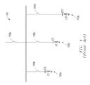
- FIG. 3 is a schematic diagram of an illustrative embodiment of the present invention.
- FIG. 4 is a schematic diagram of detuning capacitors which are included in an embodiment of the present invention.
- an offshore power distribution system 201 includes a 3.5 MW, 11 kV, 229.6 A power generator 202 , and various cable links 203 a , 203 b , 203 c , and 203 d .
- Cable link 203 d is a 15 km subsea cable.
- the dominant loads on the power distribution system 201 are nine VFDs 205 a , 205 b , 205 c , 205 d , 205 e , 205 f , 205 g , 205 h , and 205 i that are driving 300 horsepower electric motors 207 a , 207 b , 207 c , 207 d , 207 e , 207 f , 207 g , 207 h , and 207 i , which may each drive an electrical submersible pump (ESP).
- ESP electrical submersible pump
- circuit breakers 209 a , 209 b , 209 c , 209 d , 209 e , 209 f , 209 g , 209 h , and 209 i are used for switching the VFD/ESP system in and out of the circuit, and also provide system protection.
- harmonic filters 211 Without harmonic filters, the voltage total harmonic distortion (VTHD) is 21.59 percent and the current total harmonic distortion (ITHD) is 46.13 percent at the 11 kV generator switchgear 210 in the power distribution system 201 .
- Such high harmonic distortions are caused by parallel resonance due to the cable link 203 d interacting with harmonic currents injected from the input of VFDs 205 into the power distribution system 201 .
- meters (not shown) in the system 201 could develop significant errors when the harmonic distortions are larger than 20 percent.
- harmonic distortions of 10-20 percent could cause problems in relay operation. Therefore, in order to operate the power distribution system 201 , harmonic filters 211 must be installed and remain in operation at all times. As shown in FIG. 2 , the best location to install the harmonic filters 211 in the power distribution system 201 is at the 380 V motor switchgear 208 .
- the power distribution system 201 includes 380 V utility switchgear 215 for 0.5 MVA utility loads 217 , and 22 kV buses 219 a and 219 b for connecting subsea cable link 203 d and supplying power to nine ESP served wells. Other loads connected to the subsea cable link 203 d branch are lumped motors 221 and lumped static loads 223 .
- the power distribution system 201 includes three transformers 225 a , 225 b , and 225 c .
- the transformer 225 a is rated at 1 MVA and 11/0.38 kV with 5% impedance Z %.
- the transformer 225 b is rated at 3 MVA and 11/22 kV with 7% impedance Z %.
- the transformer 225 c is rated at 3 MVA and 22/0.38 kV with 7% impedance Z %.
- circuit breakers CB 1 , CB 2 , etc.
- the circuit breakers 227 a , 227 b , 227 c , 227 d , 227 e , 227 f , 227 g , and 227 h serve to switch the loads in and out of the circuit and also provide protection.
- suitable sizes for the filters 103 a , 103 b , and 103 c are 300 kVAR, 180 kVAR, and 105 kVAR, respectively. If the passive harmonic filter system 101 is installed in the power distribution system 201 as harmonic filters 211 , then when all three filters 103 a , 103 b , and 103 c are operating, the prior art passive harmonic filter system 101 can effectively mitigate harmonics in the power distribution system 201 .
- the VTHD is 1.14 percent, and the ITHD is 1.74 percent at the switchgear 208 in the power distribution system with the passive harmonic filter system 101 installed as harmonic filters 211 , compared to VTHD of 21.59 percent and ITHD of 46.13 percent at the switchgear 208 without the passive harmonic filter system 101 .
- the interlocking control will switch the 7th-harmonic filter 103 b and the 11th-harmonic filter 103 c out to protect the system and to prevent the 7th-harmonic filter 103 b and the 11th-harmonic filter 103 c from overloading, with the result that the power distribution system 201 will have no operating harmonic filters.
- the usual interlocking control strategy for the prior art passive harmonic filter system 101 is shown in Table 1.
- a passive harmonic filter system 301 includes multiple sub-filters for each harmonic.
- the inventive passive harmonic filter system 301 uses three 100 kVAR 5th-harmonic sub-filters 305 a , 305 b , and 305 c .
- each 100 kVAR 5th harmonic sub-filter 305 has its own reactor and capacitor, and is tuned at the 5th-harmonic frequency.
- Each 60 kVAR 7th-harmonic sub-filter 307 has its own reactor and capacitor and is tuned at the 7th-harmonic frequency.
- Each 35 kVAR 11th-harmonic sub-filter 311 has its own reactor and capacitor and is tuned at the 11th-harmonic frequency.
- the circuit breakers 302 , 303 , and 304 connect each set of sub-filters 305 , 307 , and 311 to a 380 V filter bus 306 .
- FIG. 3 also shows breakers/switches 302 a , 302 b , 302 c , 303 a , 303 b , 303 c , 304 a , 304 b and 304 c.
- the passive harmonic filter system 301 when used in the power distribution system 201 as the harmonic filters 211 , if one of the sub-filters 305 fails, the other two sub-filters 305 will still be able to work with the sub-filters 307 and 311 to provide effective harmonic mitigation.
- the VTHD value for the power distribution system 201 is 1.31 percent
- the ITHD value is 2.38 percent, at the switchgear 208 .
- the simulated harmonic distortions at the switchgear 208 for different scenarios with various sub-filters in operation status, are summarized in Table 2, although Table 2 shows only some of the scenarios.
- the conductor size of the reactors 315 a - c , 317 a - c , and 321 a - c for the sub-filters must be over-sized. How much over-sizing for the conductors depends on the chosen number of sub-filters at each tuned harmonic frequency by the design. On the other hand, the rms current flowing through the sub-filters is also restricted by the capacitors.
- the maximum continuous operating voltage, current, and kVAR for the capacitors are 110 percent of rated rms voltage and 120 percent of rated peak voltage, 135 percent of nominal rms current based on rated kVAR and rated voltage, and 135 percent of rated kVAR, respectively.
- the maximum continuous operating current for the capacitor is equal to 135 percent of the nominal rms current, i.e. 205.11 A. Therefore, the maximum rms current allowed to flow through each sub-filter is determined by the conductor size of the reactor and the current capability of the capacitors.
- another step to improve the overloading capability for the sub-filters 305 , 307 , and 311 is to provide taps 401 on the reactors 315 , 317 , and 321 , and add detuning capacitors 403 to the main capacitor 405 to detune the sub-filters.
- Table 3 shows the influence on the current flow on the sub-filters 305 a , 305 b , and 305 c by adding detuning capacitors 403 a and 403 b , and by adding taps 401 a , 401 b , 401 c , 401 d , and 401 e ( 401 c in the nominal 0 percent tap) on the reactors 315 a - c , 317 a - c , and 321 a - c .
- the current flowing through the sub-filter 305 is reduced by up to 32.6 percent.
- the sub-filters for each specific tuning frequency have significantly increased overloading capabilities.
- the interlocking control method for the passive harmonic filter system 301 can be flexible, depending on how many sub-filters are chosen for each tuning frequency. As long as one sub-filter 305 , one sub-filter 307 , and one sub-filter 311 remain in operation, and these sub-filters have no overloading issue in the power distribution system 201 , then the remaining sub-filters will operate without triggering the interlocking control, as shown in Table 4. However, if the power distribution system 201 has a large amount harmonic content which could heavily overload the remaining sub-filters, the interlocking control strategy can be adjusted accordingly.
- Table 4 Although the example given in Table 4 is for six-pulse VFDs, the method of designing harmonic filters, shown in Table 4, can also be used for high-pulse VFD applications such as twelve-pulse VFDs.
- the invention offers the flexibility of power factor control, which is particularly helpful for systems with only generators as the power supply.
Landscapes
- Engineering & Computer Science (AREA)
- Power Engineering (AREA)
- Supply And Distribution Of Alternating Current (AREA)
Abstract
A subsea power distribution system includes a three-phase AC power source; multiple variable frequency drives having inputs and outputs, with their inputs connected to the AC power source; an electric motor connected in series to the output of each variable frequency drive; and a passive harmonic filter system having its input connected, in parallel with the variable frequency drives, to the AC power source. The filter system includes multiple harmonic filters, each harmonic filter tuned to a specific harmonic frequency. Each harmonic filter includes a plurality of sub-filters. Each sub-filter includes a reactor connected in series to a main capacitor and one or more detuning capacitors. Each of the multiple harmonic filters is tuned to a different specific harmonic, and includes sub-filters also tuned to the same respective harmonic, and each sub-filter is sized to equally share the kVAR load of its respective harmonic filter.
Description
The present application is a continuation of U.S. patent application Ser. No. 13/006,753, filed Jan. 14, 2011, which is incorporated herein by reference in its entirety.
Field of the Invention
The present invention relates to filters for filtering out unwanted harmonics in power distribution systems that use variable-frequency drives (“VFDs”) for controlling the rotational speed of three-phase alternating current (AC) electric motors by controlling the frequency of the electrical power supplied to the motor.
Description of Related Art
Large harmonic distortions cause malfunctions of meters and relays, nuisance tripping of circuit breakers, and equipment overheating. Typical prior art single-tuned passive harmonic filters are illustrated in FIG. 3 of U.S. Pat. No. 5,444,609, which patent is incorporated herein in its entirety by reference. Such filters are tuned to a series of specific harmonic frequencies. A simplified version of FIG. 3 of U.S. Pat. No. 5,444,609 is depicted in FIG. 1 as a passive harmonic filter system 101, which includes harmonic filters 103 a, 103 b, and 103 c, respectively tuned at harmonic frequencies of the 5th, 7th, and 11th harmonics. The passive harmonic filter system 101 also includes circuit breakers or switches 105 a, 105 b, 105 c, and 105 d which serve to switch the harmonic filters in or out of the electrical power systems.
The passive harmonic filter system 101 usually has an interlocking control (not shown) among the filters during filter operation. For example, when the filter 103 a fails, the interlocking control logic turns off filters 103 b and 103 c in order to prevent them from overloading, and to prevent a serious resonance condition in the power distribution system. However, this leaves the power distribution system that was being protected by the passive harmonic filter system 101 without any harmonic filtering.
Although there are many designs for passive harmonic filters that are well known in the art, considerable shortcomings remain. What is needed is a passive harmonic filter system that will not fail when interlocking controls shut off individual parts of the filter system.
In one aspect, the present invention provides a passive harmonic filter system having its input connected, in parallel with variable frequency drives, to an AC power source, the filter system comprising multiple harmonic filters, each harmonic filter tuned to a specific harmonic frequency, each harmonic filter comprising at least three sub-filters, each sub-filter comprising: a circuit breaker or switch connected to the AC power source; an inductor or reactor connected to the circuit breaker/switch; and a capacitor connected in series to the inductor/reactor.
In another aspect of the invention, a method for constructing a subsea power distribution system is provided, comprising the steps of: (a) connecting subsea cables to a three-phase AC power source; (b) connecting the inputs of multiple variable frequency drives to the subsea cable; (c) connecting an electric motor in series to the output of each variable frequency drive; and (d) connecting the input of a passive harmonic filter system, in parallel with the variable frequency drives, to the AC power source, the filter system comprising multiple harmonic filters, each harmonic filter tuned to a specific harmonic frequency, each harmonic filter comprising at least three sub-filters, each sub-filter comprising: a circuit breaker/switch connected to the AC power source; an inductor/reactor connected to the circuit breaker/switch; and a capacitor connected in series to the inductor/reactor.
Additional objectives, features, and advantages will be apparent in the written description which follows.
The novel features characteristic of the invention are set forth in the appended claims. However, the invention itself, as well as a preferred mode of use, and further objectives and advantages thereof, will best be understood by reference to the following detailed description when read in conjunction with the accompanying drawings in which the left-most significant digit in the reference numerals denotes the first figure in which the respective reference numerals appear, wherein:
While the invention is susceptible to various modifications and alternative forms, specific embodiments thereof have been shown by way of example in the drawings and are herein described in detail. It should be understood, however, that the description herein of specific embodiments is not intended to limit the invention to the particular forms disclosed, but on the contrary, the intention is to cover all modifications, equivalents, and alternatives falling within the scope of the invention as defined by the appended claims.
Illustrative embodiments of the invention are described below. In the interest of clarity, not all features of an actual implementation are described in this specification. It will of course be appreciated that in the development of any such actual embodiment, numerous implementation-specific decisions must be made to achieve the developer's specific goals, such as compliance with system-related and business-related constraints, which will vary from one implementation to another. Moreover, it will be appreciated that such a development effort might be complex and time-consuming, but would nevertheless be a routine undertaking for those of ordinary skill in the art having the benefit of this disclosure.
Referring now to FIG. 2 , an offshore power distribution system 201 includes a 3.5 MW, 11 kV, 229.6 A power generator 202, and various cable links 203 a, 203 b, 203 c, and 203 d. Cable link 203 d is a 15 km subsea cable.
The dominant loads on the power distribution system 201 are nine VFDs 205 a, 205 b, 205 c, 205 d, 205 e, 205 f, 205 g, 205 h, and 205 i that are driving 300 horsepower electric motors 207 a, 207 b, 207 c, 207 d, 207 e, 207 f, 207 g, 207 h, and 207 i, which may each drive an electrical submersible pump (ESP). Between each VFD 205 and a 380 V motor switchgear 208 are circuit breakers 209 a, 209 b, 209 c, 209 d, 209 e, 209 f, 209 g, 209 h, and 209 i, which are used for switching the VFD/ESP system in and out of the circuit, and also provide system protection.
Without harmonic filters, the voltage total harmonic distortion (VTHD) is 21.59 percent and the current total harmonic distortion (ITHD) is 46.13 percent at the 11 kV generator switchgear 210 in the power distribution system 201. Such high harmonic distortions are caused by parallel resonance due to the cable link 203 d interacting with harmonic currents injected from the input of VFDs 205 into the power distribution system 201. Based on IEEE Standare 519-1992, meters (not shown) in the system 201 could develop significant errors when the harmonic distortions are larger than 20 percent. Also, harmonic distortions of 10-20 percent could cause problems in relay operation. Therefore, in order to operate the power distribution system 201, harmonic filters 211 must be installed and remain in operation at all times. As shown in FIG. 2 , the best location to install the harmonic filters 211 in the power distribution system 201 is at the 380 V motor switchgear 208.
The power distribution system 201 includes 380 V utility switchgear 215 for 0.5 MVA utility loads 217, and 22 kV buses 219 a and 219 b for connecting subsea cable link 203 d and supplying power to nine ESP served wells. Other loads connected to the subsea cable link 203 d branch are lumped motors 221 and lumped static loads 223. The power distribution system 201 includes three transformers 225 a, 225 b, and 225 c. The transformer 225 a is rated at 1 MVA and 11/0.38 kV with 5% impedance Z %. The transformer 225 b is rated at 3 MVA and 11/22 kV with 7% impedance Z %. The transformer 225 c is rated at 3 MVA and 22/0.38 kV with 7% impedance Z %. As can be seen in FIG. 2 , at various places in the power distribution system 201 are circuit breakers (CB1, CB2, etc.) 227. The circuit breakers 227 a, 227 b, 227 c, 227 d, 227 e, 227 f, 227 g, and 227 h serve to switch the loads in and out of the circuit and also provide protection.
Referring back to the prior art passive harmonic filter system 101 of FIG. 1 , suitable sizes for the filters 103 a, 103 b, and 103 c are 300 kVAR, 180 kVAR, and 105 kVAR, respectively. If the passive harmonic filter system 101 is installed in the power distribution system 201 as harmonic filters 211, then when all three filters 103 a, 103 b, and 103 c are operating, the prior art passive harmonic filter system 101 can effectively mitigate harmonics in the power distribution system 201. The VTHD is 1.14 percent, and the ITHD is 1.74 percent at the switchgear 208 in the power distribution system with the passive harmonic filter system 101 installed as harmonic filters 211, compared to VTHD of 21.59 percent and ITHD of 46.13 percent at the switchgear 208 without the passive harmonic filter system 101.
However, when the 5th-harmonic filter 103 a fails, the interlocking control will switch the 7th-harmonic filter 103 b and the 11th-harmonic filter 103 c out to protect the system and to prevent the 7th-harmonic filter 103 b and the 11th-harmonic filter 103 c from overloading, with the result that the power distribution system 201 will have no operating harmonic filters. The usual interlocking control strategy for the prior art passive harmonic filter system 101 is shown in Table 1.
| TABLE 1 |
| Interlocking Control for Traditional Passive Harmonic Filters |
| Conditions triggering | |
| interlocking control | Interlocking Control |
| 5th |
7th and 11th |
| 103c OFF (No filters in the system) | |
| 5th and 7th harmonic filters | 11th |
| 103a, 103b fail | in the system) |
| 7th |
5th |
| |
|
Referring now to FIG. 3 , one preferred embodiment of the present invention is depicted. A passive harmonic filter system 301 includes multiple sub-filters for each harmonic. Thus, for the 5th-harmonic filter, instead of using a 300 kVAR 5th-harmonic filter 103 a as shown in FIG. 1 , the inventive passive harmonic filter system 301 uses three 100 kVAR 5th- harmonic sub-filters 305 a, 305 b, and 305 c. Similarly, there are three 60 kVAR 7th- harmonic sub-filters 307 a, 307 b, and 307 c, and three 35 kVAR 11th- harmonic sub-filters 311 a, 311 b, and 311 c. Each 100 kVAR 5th harmonic sub-filter 305 has its own reactor and capacitor, and is tuned at the 5th-harmonic frequency. Each 60 kVAR 7th-harmonic sub-filter 307 has its own reactor and capacitor and is tuned at the 7th-harmonic frequency. Each 35 kVAR 11th-harmonic sub-filter 311 has its own reactor and capacitor and is tuned at the 11th-harmonic frequency. The circuit breakers 302, 303, and 304 connect each set of sub-filters 305, 307, and 311 to a 380 V filter bus 306. FIG. 3 also shows breakers/switches 302 a, 302 b, 302 c, 303 a, 303 b, 303 c, 304 a, 304 b and 304 c.
Referring back to FIG. 2 , when the passive harmonic filter system 301 is used in the power distribution system 201 as the harmonic filters 211, if one of the sub-filters 305 fails, the other two sub-filters 305 will still be able to work with the sub-filters 307 and 311 to provide effective harmonic mitigation. For the case when one sub-filter 305 fails, and two sub-filters 305, three sub-filters 307, and three sub-filters 311 remain in operation, the VTHD value for the power distribution system 201 is 1.31 percent, and the ITHD value is 2.38 percent, at the switchgear 208. The simulated harmonic distortions at the switchgear 208, for different scenarios with various sub-filters in operation status, are summarized in Table 2, although Table 2 shows only some of the scenarios.
| TABLE 2 |
| Summary of Simulated Harmonic Distortions |
| ITHD, | ||
| Sub-filters operating status | VTHD, % | % |
| All sub-filters out of service | 21.59 | 46.13 |
| All sub-filters in service | 1.14 | 1.74 |
| One sub-filter 305 out of service; two sub-filters | 1.31 | 2.38 |
| 305, and all sub-filters, 307 and 311, in service | ||
| One sub-filter 307 out of service; three sub-filters | 1.24 | 1.96 |
| 305, two sub-filters 307, and three sub-filters 311 in | ||
| service | ||
| One sub-filter 311 out of service; three sub-filters | 1.26 | 1.86 |
| 305, three sub-filters 307, and two sub-filters 311 in | ||
| service | ||
| One sub-filter 305, and one sub-filter 307, out of | 1.39 | 2.48 |
| service; two sub-filters 305, two sub-filters 307, | ||
| and three sub-filters 311 in service | ||
| One sub-filter 305, and one sub-filter 311, out of | 1.41 | 2.43 |
| service; two sub-filters 305, three sub-filters 307, | ||
| and two sub-filters 311 in service | ||
| One sub-filter 307, and one sub-filter 311, out of | 1.35 | 2.02 |
| service; three sub-filters 305, two sub-filters 307, | ||
| and two sub-filters 311 in service | ||
| One sub-filter 305, one sub-filter 307, and one sub- | 1.49 | 2.52 |
| filter 311 out of service; two sub-filters 305, two | ||
| sub-filters 307, and two sub-filters 311 in service | ||
| Two sub-filters 305 out of service; one sub-filter | 2.01 | 4.54 |
| 305, three sub-filters 307, and three sub-filters 311 | ||
| in service (If the one remaining sub-filter 305 is not | ||
| overloading) | ||
| Two sub-filters 307 out of service; three sub- | 1.63 | 2.73 |
| filters 305, one sub-filter 307, and three sub-filters | ||
| 311 in service (If the one remaining sub-filter 307 | ||
| is not overloading) | ||
| Two sub-filters 311 out of service; three sub-filters | 1.50 | 2.07 |
| 305, three sub-filters 307, and one sub-filter 311 in | ||
| service (If the one remaining sub-filter 311 is not | ||
| overloading) | ||
Depending on the harmonic content in the power distribution system 201, when one or two sub-filters fail for each specific filter tuning frequency, the remaining sub-filters are very likely to be overloading. In order to avoid the overloading problem, the conductor size of the reactors 315 a-c, 317 a-c, and 321 a-c for the sub-filters must be over-sized. How much over-sizing for the conductors depends on the chosen number of sub-filters at each tuned harmonic frequency by the design. On the other hand, the rms current flowing through the sub-filters is also restricted by the capacitors. Based on IEEE Standard 18-2002, the maximum continuous operating voltage, current, and kVAR for the capacitors are 110 percent of rated rms voltage and 120 percent of rated peak voltage, 135 percent of nominal rms current based on rated kVAR and rated voltage, and 135 percent of rated kVAR, respectively. For example, for the 100 kVAR 5th sub-filter 305 a (rated at 380 V), the nominal rms current is I=Q/(√{square root over (3)}U)=100/(1.732*0.38)=151.93 A, the maximum continuous operating current for the capacitor is equal to 135 percent of the nominal rms current, i.e. 205.11 A. Therefore, the maximum rms current allowed to flow through each sub-filter is determined by the conductor size of the reactor and the current capability of the capacitors.
Referring now to FIG. 4 , another step to improve the overloading capability for the sub-filters 305, 307, and 311, is to provide taps 401 on the reactors 315, 317, and 321, and add detuning capacitors 403 to the main capacitor 405 to detune the sub-filters. Table 3 shows the influence on the current flow on the sub-filters 305 a, 305 b, and 305 c by adding detuning capacitors 403 a and 403 b, and by adding taps 401 a, 401 b, 401 c, 401 d, and 401 e (401 c in the nominal 0 percent tap) on the reactors 315 a-c, 317 a-c, and 321 a-c. By adding the taps 401 a-e and the detuning capacitors 403 a and 403 b on each of the 100 kVAR sub-filters 305 a, 305 b, and 305 c, the current flowing through the sub-filter 305 is reduced by up to 32.6 percent. Further, by properly choosing over-sized conductors for the reactors and combining with the taps 401 a-e on the reactors and the detuning capacitors 403 a and 403 b, the sub-filters for each specific tuning frequency have significantly increased overloading capabilities.
| TABLE 3 |
| Improvements Using Detuning Capacitors and Taps |
| Parameters | Tuning | Current of sub- |
| Rated voltage, V | 380 | frequency in | filter varied from |
| Rated frequency, Hz | 50 | harmonic order | nominal, percent |
| Nominal main capacitors, | 100 | 4.8 | 0 |
| kVAR | |||
| Detuning capacitor, kVAR | 15 | 4.48 | −16.6 |
| 30 | 4.21 | −24.6 | |
| Taps on reactor | +8% | 4.62 | −15.5 |
| +4% | 4.71 | −8.5 | |
| 0% | 4.80 | 0 | |
| −4% | 4.90 | +10.3 | |
| −8% | 5.00 | +23.0 | |
| 15 kVAR detuning capacitor | +8% | 4.31 | −27.1 |
| and taps on reactor | +4% | 4.39 | −22.3 |
| 0% | 4.48 | −16.6 | |
| −4% | 4.57 | −9.8 | |
| −8% | 4.67 | −1.6 | |
| 30 kVAR detuning capacitor | +8% | 4.05 | −32.6 |
| and taps on reactor | +4% | 4.13 | −28.9 |
| 0% | 4.21 | −24.6 | |
| −4% | 4.30 | −19.6 | |
| −8% | 4.39 | −13.5 | |
The interlocking control method for the passive harmonic filter system 301 can be flexible, depending on how many sub-filters are chosen for each tuning frequency. As long as one sub-filter 305, one sub-filter 307, and one sub-filter 311 remain in operation, and these sub-filters have no overloading issue in the power distribution system 201, then the remaining sub-filters will operate without triggering the interlocking control, as shown in Table 4. However, if the power distribution system 201 has a large amount harmonic content which could heavily overload the remaining sub-filters, the interlocking control strategy can be adjusted accordingly.
Although the example given in Table 4 is for six-pulse VFDs, the method of designing harmonic filters, shown in Table 4, can also be used for high-pulse VFD applications such as twelve-pulse VFDs.
| TABLE 4 |
| Interlocking Control Strategy |
| Conditions Trigging | |
| Interlocking Control | Interlocking Control |
| All sub-filters 305 | All sub-filters 307 and 311 OFF (no filters in the |
| fail | system) |
| All sub-filters 305, | All sub-filters 311 OFF (no filters in the system) |
| and all sub-filters 307 | |
| fail | |
| All sub-filters 307 | All sub-filters 305 ON, and all sub-filters 311 |
| fail | OFF |
During operation, if one or more sub-filters fail, the remaining sub-filters for a specific tuning frequency will still work and continue to provide harmonic filtering. The chances that all sub-filters must be switched off due to the interlocking control are significantly reduced. The invention offers the flexibility of power factor control, which is particularly helpful for systems with only generators as the power supply.
The particular embodiments disclosed above are illustrative only, as the invention may be modified and practiced in different but equivalent manners apparent to those skilled in the art having the benefit of the teachings herein. Furthermore, no limitations are intended to the details of construction or design herein shown, other than as described in the claims below. Accordingly, the protection sought herein is as set forth in the claims below. Although the present invention is shown in a limited number of forms, it is not limited to just these forms, but is amenable to various changes and modifications.
Claims (4)
1. A power distribution system comprising:
a power source;
a switchgear in electrical communication with the power source;
a passive harmonic filter system having its input connected, in parallel with at least one variable frequency drive, to the switchgear, the filter system comprising multiple harmonic filters, each harmonic filter tuned to a specific harmonic frequency, each harmonic filter comprising a plurality of sub-filters, each sub-filter comprising:
a circuit breaker/switch connected to the power source;
a reactor connected to the circuit breaker/switch; and
a main capacitor and one or more detuning capacitors connected in series to the reactor such that a current flowing through each sub-filter is reduced by the one or more detuning capacitors; and
an electrical submersible pump system comprising an electric motor connected to at least one variable frequency drive.
2. The system of claim 1 , wherein the multiple harmonic filters comprise three harmonic filters, a first harmonic filter tuned to a 5th-harmonic, a second harmonic filter tuned to a 7th harmonic, and a third harmonic filter tuned to a 11th harmonic, and wherein each sub-filter of each harmonic filter is tuned to the same harmonic of its respective harmonic filter, and each sub-filter is sized to equally share a kVAR load of its respective harmonic filter.
3. The system of claim 2 , wherein each reactor has a plurality of taps located thereon.
4. The system of claim 1 wherein each capacitor of a given sub-filter is sized to equally share a kVAR load of its respective harmonic filter.
Priority Applications (1)
| Application Number | Priority Date | Filing Date | Title |
|---|---|---|---|
| US14/629,878 US9503042B2 (en) | 2011-01-14 | 2015-02-24 | Passive harmonic filter for power distribution systems |
Applications Claiming Priority (2)
| Application Number | Priority Date | Filing Date | Title |
|---|---|---|---|
| US13/006,753 US8994226B2 (en) | 2011-01-14 | 2011-01-14 | Passive harmonic filter for power distribution systems |
| US14/629,878 US9503042B2 (en) | 2011-01-14 | 2015-02-24 | Passive harmonic filter for power distribution systems |
Related Parent Applications (1)
| Application Number | Title | Priority Date | Filing Date |
|---|---|---|---|
| US13/006,753 Continuation US8994226B2 (en) | 2011-01-14 | 2011-01-14 | Passive harmonic filter for power distribution systems |
Publications (2)
| Publication Number | Publication Date |
|---|---|
| US20150171818A1 US20150171818A1 (en) | 2015-06-18 |
| US9503042B2 true US9503042B2 (en) | 2016-11-22 |
Family
ID=46490332
Family Applications (2)
| Application Number | Title | Priority Date | Filing Date |
|---|---|---|---|
| US13/006,753 Active 2033-03-22 US8994226B2 (en) | 2011-01-14 | 2011-01-14 | Passive harmonic filter for power distribution systems |
| US14/629,878 Expired - Fee Related US9503042B2 (en) | 2011-01-14 | 2015-02-24 | Passive harmonic filter for power distribution systems |
Family Applications Before (1)
| Application Number | Title | Priority Date | Filing Date |
|---|---|---|---|
| US13/006,753 Active 2033-03-22 US8994226B2 (en) | 2011-01-14 | 2011-01-14 | Passive harmonic filter for power distribution systems |
Country Status (1)
| Country | Link |
|---|---|
| US (2) | US8994226B2 (en) |
Cited By (1)
| Publication number | Priority date | Publication date | Assignee | Title |
|---|---|---|---|---|
| US10901026B2 (en) * | 2018-09-18 | 2021-01-26 | Tci, Llc | Passive harmonic filter power quality monitor and communications device |
Families Citing this family (6)
| Publication number | Priority date | Publication date | Assignee | Title |
|---|---|---|---|---|
| CN103078320B (en) * | 2012-11-19 | 2014-12-31 | 国网智能电网研究院 | Method for treating high-voltage harmonic source |
| EP3065247B1 (en) * | 2015-03-05 | 2017-05-10 | "Condensator Dominit" Dr. Christian Dresel Gesellschaft für Leistungselektronik, Energietechnik und Netzqualität mbH | Passiv filter for AC noise |
| US9667063B1 (en) | 2016-02-19 | 2017-05-30 | Wilsun Xu | Harmonic filter for multipulse converter systems |
| CN105676766A (en) * | 2016-03-15 | 2016-06-15 | 万华生态板业(荆州)有限公司 | Real-time monitoring circuit of high-speed centrifugal atomizer used for artificial board |
| SG10201902753RA (en) * | 2018-04-12 | 2019-11-28 | Skyworks Solutions Inc | Filter Including Two Types Of Acoustic Wave Resonators |
| US11487040B2 (en) | 2020-06-29 | 2022-11-01 | Baker Hughes Oilfield Operations Llc | Multi-frequency tuning network system and method |
Citations (5)
| Publication number | Priority date | Publication date | Assignee | Title |
|---|---|---|---|---|
| US5387821A (en) * | 1992-11-12 | 1995-02-07 | Allegro Microsystems, Inc. | Power distribution circuit with power factor correction and independent harmonic current filter |
| US5444609A (en) * | 1993-03-25 | 1995-08-22 | Energy Management Corporation | Passive harmonic filter system for variable frequency drives |
| US6009004A (en) * | 1997-06-30 | 1999-12-28 | Mte Corporation | Single-phase harmonic filter system |
| US6127743A (en) * | 1999-04-09 | 2000-10-03 | Ontario Inc. | Universal harmonic mitigating system |
| US7602136B2 (en) * | 2006-04-24 | 2009-10-13 | Power Conservation, Ltd. | Mitigation of harmonic currents and conservation of power in non-linear load systems |
-
2011
- 2011-01-14 US US13/006,753 patent/US8994226B2/en active Active
-
2015
- 2015-02-24 US US14/629,878 patent/US9503042B2/en not_active Expired - Fee Related
Patent Citations (5)
| Publication number | Priority date | Publication date | Assignee | Title |
|---|---|---|---|---|
| US5387821A (en) * | 1992-11-12 | 1995-02-07 | Allegro Microsystems, Inc. | Power distribution circuit with power factor correction and independent harmonic current filter |
| US5444609A (en) * | 1993-03-25 | 1995-08-22 | Energy Management Corporation | Passive harmonic filter system for variable frequency drives |
| US6009004A (en) * | 1997-06-30 | 1999-12-28 | Mte Corporation | Single-phase harmonic filter system |
| US6127743A (en) * | 1999-04-09 | 2000-10-03 | Ontario Inc. | Universal harmonic mitigating system |
| US7602136B2 (en) * | 2006-04-24 | 2009-10-13 | Power Conservation, Ltd. | Mitigation of harmonic currents and conservation of power in non-linear load systems |
Non-Patent Citations (7)
| Title |
|---|
| Elham B. Makram et al, "Harmonic Filter Design Using Actual Recorded Data", IEEE Transactions on Industry Applications, vol. 29 No. 6, Nov./Dec. 1993, pp. 1176-1183. |
| J.C. Das, "Passive Filters-Potentialities and Limitations", IEEE Transactions on Industry Applications, vol. 40, No. 1, Jan./Feb. 2004, pp. 232-241. |
| Liang et al. (Passive Harmonic Filter Design Scheme for Subsea Cable Applications with 6-Pulse Variable Frequency Drives). * |
| Maria Emilia De Lima Tostes, et al, "Impacts Over the Distribution Grid from the Adoption of Distributed Harmonic Filters on Low-Voltage Customers", IEEE Transactions on Power Delivery, vol. 20, No. 1, Jan. 2005, p. 384-389. |
| Passive Harmonic Filter Design Scheme for Subsea Cable Applications with 6-Pulse Variable Frequency Drives. * |
| Robert L. Almonte, et al, Harmonics at the Utility Industrial Interface: a Real World Example, IEEE Transactions on Industrial Applications, vol. 31, No. 6, Nov./Dec. 1995, pp. 1419-1426. |
| Xiaodong Liang, et al, "Passive Harmonic Filter Design Scheme for Subsea Cable Application with 6-Pulse Variable Frequency Drives," Proceedings of IEEE 2009 Energy Conversion Congress and Exposition (ECCE), San Jose, CA, USA, Sep. 20-24, 2009, pp. 597-603. |
Cited By (1)
| Publication number | Priority date | Publication date | Assignee | Title |
|---|---|---|---|---|
| US10901026B2 (en) * | 2018-09-18 | 2021-01-26 | Tci, Llc | Passive harmonic filter power quality monitor and communications device |
Also Published As
| Publication number | Publication date |
|---|---|
| US20120182089A1 (en) | 2012-07-19 |
| US20150171818A1 (en) | 2015-06-18 |
| US8994226B2 (en) | 2015-03-31 |
Similar Documents
| Publication | Publication Date | Title |
|---|---|---|
| US9503042B2 (en) | Passive harmonic filter for power distribution systems | |
| US11888308B2 (en) | Modular facts devices with external fault current protection | |
| CN107947173B (en) | Series compensator and control method | |
| CN102082432B (en) | Cascade converter station and cascade multi-terminal high-voltage direct-current transmission system | |
| EP1787383B1 (en) | Convertible high voltage direct current installation | |
| CN104113060A (en) | Convertible static synchronous series compensator | |
| US4622474A (en) | Alternating-current filter circuit arrangement | |
| SA110310077B1 (en) | Poly-Phase Reactive Power Compensator | |
| US7923867B2 (en) | Electromagnetic noise suppression system for Wye power distribution | |
| Hassan et al. | Review of ferroresonance in power distribution grids | |
| US9917475B2 (en) | Variable neutral impedance for multi-source system | |
| CA2727972C (en) | Passive harmonic filter for power distribution systems | |
| CN107171270B (en) | Intensive ice melting device constant current, constant voltage modular dynamic reactive power compensation components | |
| US11271469B2 (en) | Device and method for suppressing harmonic distortions at the output of variable frequency drive | |
| Liang et al. | Power system optimization for industrial facilities using power studies | |
| Pontt et al. | Resonance effects, power quality and reliability issues of high-power converters-fed drives employed in modern SAG circuits | |
| KR20200007164A (en) | Mmc hvdc system using zig-zag transformer with harmonic injection function | |
| CN223666046U (en) | Multi-machine parallel system | |
| KR102083137B1 (en) | Protection of Inductive Elements | |
| EP3340409B1 (en) | Inductive element protection in a power supply system | |
| Cocchiara et al. | Performances of the Fault Decoupling Device when unbalanced and multiple faults occur on distribution systems | |
| Almelian | Optimal design of passive filter to mitigate harmonic in power frequency | |
| Baskar | Power Quality Analysis and Power System Study in High Voltage Systems | |
| Varma et al. | Adverse harmonic impact of network resonances on smart meters | |
| Singh | Harmonic solutions to commercial and industrial electrical power systems |
Legal Events
| Date | Code | Title | Description |
|---|---|---|---|
| STCF | Information on status: patent grant |
Free format text: PATENTED CASE |
|
| FEPP | Fee payment procedure |
Free format text: MAINTENANCE FEE REMINDER MAILED (ORIGINAL EVENT CODE: REM.); ENTITY STATUS OF PATENT OWNER: LARGE ENTITY |
|
| LAPS | Lapse for failure to pay maintenance fees |
Free format text: PATENT EXPIRED FOR FAILURE TO PAY MAINTENANCE FEES (ORIGINAL EVENT CODE: EXP.); ENTITY STATUS OF PATENT OWNER: LARGE ENTITY |
|
| STCH | Information on status: patent discontinuation |
Free format text: PATENT EXPIRED DUE TO NONPAYMENT OF MAINTENANCE FEES UNDER 37 CFR 1.362 |
|
| FP | Lapsed due to failure to pay maintenance fee |
Effective date: 20201122 |