US9502860B1 - Eliminating unwanted optical output power from a multi-device tunable laser by using a wavelength blocking component - Google Patents
Eliminating unwanted optical output power from a multi-device tunable laser by using a wavelength blocking component Download PDFInfo
- Publication number
- US9502860B1 US9502860B1 US14/211,593 US201414211593A US9502860B1 US 9502860 B1 US9502860 B1 US 9502860B1 US 201414211593 A US201414211593 A US 201414211593A US 9502860 B1 US9502860 B1 US 9502860B1
- Authority
- US
- United States
- Prior art keywords
- wavelength
- tunable laser
- laser source
- tunable
- output
- Prior art date
- Legal status (The legal status is an assumption and is not a legal conclusion. Google has not performed a legal analysis and makes no representation as to the accuracy of the status listed.)
- Expired - Fee Related
Links
Images


Classifications
-
- H—ELECTRICITY
- H01—ELECTRIC ELEMENTS
- H01S—DEVICES USING THE PROCESS OF LIGHT AMPLIFICATION BY STIMULATED EMISSION OF RADIATION [LASER] TO AMPLIFY OR GENERATE LIGHT; DEVICES USING STIMULATED EMISSION OF ELECTROMAGNETIC RADIATION IN WAVE RANGES OTHER THAN OPTICAL
- H01S5/00—Semiconductor lasers
- H01S5/06—Arrangements for controlling the laser output parameters, e.g. by operating on the active medium
-
- H—ELECTRICITY
- H01—ELECTRIC ELEMENTS
- H01S—DEVICES USING THE PROCESS OF LIGHT AMPLIFICATION BY STIMULATED EMISSION OF RADIATION [LASER] TO AMPLIFY OR GENERATE LIGHT; DEVICES USING STIMULATED EMISSION OF ELECTROMAGNETIC RADIATION IN WAVE RANGES OTHER THAN OPTICAL
- H01S5/00—Semiconductor lasers
- H01S5/005—Optical components external to the laser cavity, specially adapted therefor, e.g. for homogenisation or merging of the beams or for manipulating laser pulses, e.g. pulse shaping
- H01S5/0078—Optical components external to the laser cavity, specially adapted therefor, e.g. for homogenisation or merging of the beams or for manipulating laser pulses, e.g. pulse shaping for frequency filtering
-
- H—ELECTRICITY
- H01—ELECTRIC ELEMENTS
- H01S—DEVICES USING THE PROCESS OF LIGHT AMPLIFICATION BY STIMULATED EMISSION OF RADIATION [LASER] TO AMPLIFY OR GENERATE LIGHT; DEVICES USING STIMULATED EMISSION OF ELECTROMAGNETIC RADIATION IN WAVE RANGES OTHER THAN OPTICAL
- H01S5/00—Semiconductor lasers
- H01S5/06—Arrangements for controlling the laser output parameters, e.g. by operating on the active medium
- H01S5/062—Arrangements for controlling the laser output parameters, e.g. by operating on the active medium by varying the potential of the electrodes
- H01S5/06203—Transistor-type lasers
- H01S5/06206—Controlling the frequency of the radiation, e.g. tunable twin-guide lasers [TTG]
-
- H—ELECTRICITY
- H01—ELECTRIC ELEMENTS
- H01S—DEVICES USING THE PROCESS OF LIGHT AMPLIFICATION BY STIMULATED EMISSION OF RADIATION [LASER] TO AMPLIFY OR GENERATE LIGHT; DEVICES USING STIMULATED EMISSION OF ELECTROMAGNETIC RADIATION IN WAVE RANGES OTHER THAN OPTICAL
- H01S5/00—Semiconductor lasers
- H01S5/10—Construction or shape of the optical resonator, e.g. extended or external cavity, coupled cavities, bent-guide, varying width, thickness or composition of the active region
- H01S5/14—External cavity lasers
- H01S5/141—External cavity lasers using a wavelength selective device, e.g. a grating or etalon
-
- H—ELECTRICITY
- H01—ELECTRIC ELEMENTS
- H01S—DEVICES USING THE PROCESS OF LIGHT AMPLIFICATION BY STIMULATED EMISSION OF RADIATION [LASER] TO AMPLIFY OR GENERATE LIGHT; DEVICES USING STIMULATED EMISSION OF ELECTROMAGNETIC RADIATION IN WAVE RANGES OTHER THAN OPTICAL
- H01S5/00—Semiconductor lasers
- H01S5/40—Arrangement of two or more semiconductor lasers, not provided for in groups H01S5/02 - H01S5/30
- H01S5/4025—Array arrangements, e.g. constituted by discrete laser diodes or laser bar
- H01S5/4087—Array arrangements, e.g. constituted by discrete laser diodes or laser bar emitting more than one wavelength
-
- H—ELECTRICITY
- H01—ELECTRIC ELEMENTS
- H01S—DEVICES USING THE PROCESS OF LIGHT AMPLIFICATION BY STIMULATED EMISSION OF RADIATION [LASER] TO AMPLIFY OR GENERATE LIGHT; DEVICES USING STIMULATED EMISSION OF ELECTROMAGNETIC RADIATION IN WAVE RANGES OTHER THAN OPTICAL
- H01S3/00—Lasers, i.e. devices using stimulated emission of electromagnetic radiation in the infrared, visible or ultraviolet wave range
- H01S3/05—Construction or shape of optical resonators; Accommodation of active medium therein; Shape of active medium
- H01S3/06—Construction or shape of active medium
- H01S3/063—Waveguide lasers, i.e. whereby the dimensions of the waveguide are of the order of the light wavelength
- H01S3/067—Fibre lasers
- H01S3/0675—Resonators including a grating structure, e.g. distributed Bragg reflectors [DBR] or distributed feedback [DFB] fibre lasers
-
- H—ELECTRICITY
- H01—ELECTRIC ELEMENTS
- H01S—DEVICES USING THE PROCESS OF LIGHT AMPLIFICATION BY STIMULATED EMISSION OF RADIATION [LASER] TO AMPLIFY OR GENERATE LIGHT; DEVICES USING STIMULATED EMISSION OF ELECTROMAGNETIC RADIATION IN WAVE RANGES OTHER THAN OPTICAL
- H01S3/00—Lasers, i.e. devices using stimulated emission of electromagnetic radiation in the infrared, visible or ultraviolet wave range
- H01S3/05—Construction or shape of optical resonators; Accommodation of active medium therein; Shape of active medium
- H01S3/08—Construction or shape of optical resonators or components thereof
- H01S3/08004—Construction or shape of optical resonators or components thereof incorporating a dispersive element, e.g. a prism for wavelength selection
- H01S3/08009—Construction or shape of optical resonators or components thereof incorporating a dispersive element, e.g. a prism for wavelength selection using a diffraction grating
-
- H—ELECTRICITY
- H01—ELECTRIC ELEMENTS
- H01S—DEVICES USING THE PROCESS OF LIGHT AMPLIFICATION BY STIMULATED EMISSION OF RADIATION [LASER] TO AMPLIFY OR GENERATE LIGHT; DEVICES USING STIMULATED EMISSION OF ELECTROMAGNETIC RADIATION IN WAVE RANGES OTHER THAN OPTICAL
- H01S3/00—Lasers, i.e. devices using stimulated emission of electromagnetic radiation in the infrared, visible or ultraviolet wave range
- H01S3/10—Controlling the intensity, frequency, phase, polarisation or direction of the emitted radiation, e.g. switching, gating, modulating or demodulating
- H01S3/10007—Controlling the intensity, frequency, phase, polarisation or direction of the emitted radiation, e.g. switching, gating, modulating or demodulating in optical amplifiers
- H01S3/10023—Controlling the intensity, frequency, phase, polarisation or direction of the emitted radiation, e.g. switching, gating, modulating or demodulating in optical amplifiers by functional association of additional optical elements, e.g. filters, gratings, reflectors
- H01S3/1003—Controlling the intensity, frequency, phase, polarisation or direction of the emitted radiation, e.g. switching, gating, modulating or demodulating in optical amplifiers by functional association of additional optical elements, e.g. filters, gratings, reflectors tunable optical elements, e.g. acousto-optic filters, tunable gratings
-
- H—ELECTRICITY
- H01—ELECTRIC ELEMENTS
- H01S—DEVICES USING THE PROCESS OF LIGHT AMPLIFICATION BY STIMULATED EMISSION OF RADIATION [LASER] TO AMPLIFY OR GENERATE LIGHT; DEVICES USING STIMULATED EMISSION OF ELECTROMAGNETIC RADIATION IN WAVE RANGES OTHER THAN OPTICAL
- H01S5/00—Semiconductor lasers
- H01S5/02—Structural details or components not essential to laser action
- H01S5/022—Mountings; Housings
- H01S5/0225—Out-coupling of light
- H01S5/02251—Out-coupling of light using optical fibres
-
- H—ELECTRICITY
- H01—ELECTRIC ELEMENTS
- H01S—DEVICES USING THE PROCESS OF LIGHT AMPLIFICATION BY STIMULATED EMISSION OF RADIATION [LASER] TO AMPLIFY OR GENERATE LIGHT; DEVICES USING STIMULATED EMISSION OF ELECTROMAGNETIC RADIATION IN WAVE RANGES OTHER THAN OPTICAL
- H01S5/00—Semiconductor lasers
- H01S5/40—Arrangement of two or more semiconductor lasers, not provided for in groups H01S5/02 - H01S5/30
- H01S5/4012—Beam combining, e.g. by the use of fibres, gratings, polarisers, prisms
Definitions
- the present invention relates generally to a system and method to block the output of one or more individual undesired laser sources in a tunable swept multi-laser system to reduce the effect of the non-desired laser sources on the output of the system.
- tunable laser sources are often used in optical systems as tunable swept laser sources. However, because it is common for the wavelength range of a single tunable laser to be insufficiently wide for the desired performance of the system, the output of multiple tunable laser sources are often combined to achieve the proper wavelength range for the application. In such a tunable swept multi-laser system, it is desirable to have only a single laser output electromagnetic radiation into the optical system at a given time.
- the output of multiple laser sources is combined using an optical coupler and non-desired tunable laser sources in the system are simply turned off.
- turning off non-desired laser sources has the consequence of increasing scanning time and/or instability of the swept laser signal.
- the system can either wait for the laser output to stabilize by pausing data collection or acquire individual data sets for each tunable laser sweep and, in post processing, combine the separate datasets into one combined dataset. Both of these strategies require additional time resulting in a reduced sweep speed and a slower repetition rate.
- WDM wavelength division multiplexer
- Another alternative is to power off the semiconductor optical amplifier. However, the laser continues to output light when the semiconductor optical amplifier is turned off, and the leakage power may contaminate the overall spectrum of the signal.
- the present disclosure provides a system and method for blocking, in a tunable swept multi-laser system, the output of at least one laser using wavelength blocking components to control the spectral quality of the electromagnetic output of the tunable swept multi-laser system.
- a tunable swept multi-laser system includes a first laser source having a first wavelength working range wherein the first wavelength working range begins at a first start wavelength and ends at a first end wavelength.
- the system also includes a second laser source having a second wavelength working range wherein the second wavelength working range begins at a second start wavelength and ends at a second end wavelength.
- the system further includes a first wavelength blocking component having a first wavelength blocking range, wherein the first wavelength blocking component is optically coupled with the first laser source, the first wavelength blocking range including the first end wavelength, and a second wavelength blocking component having a second wavelength blocking range, wherein the second wavelength blocking component is optically coupled with the second laser source, the second wavelength blocking range including the second start wavelength. There is an overlap between the first wavelength working range and the second wavelength working range.
- the system further includes a coupler having a first optical input, a second optical input, and an optical output.
- the first optical input is coupled with the first laser source
- the second optical input is coupled with the second laser source
- the optical output is configured to emit the combined output of the first laser source and the second laser source.
- the first start wavelength is smaller than the second start wavelength and the first end wavelength is smaller than the second end wavelength.
- the first end wavelength blocking range is a slightly lower wavelength than the second wavelength start blocking range.
- system further includes a start wavelength blocking component optically coupled with the first laser source and having an ending blocking range, the end wavelength blocking range including the first end wavelength, and a start wavelength blocking component optically coupled with the second laser source and having a start wavelength blocking range, the start wavelength blocking range including the second start wavelength.
- the first laser source and the second laser source are Semiconductor Monolithic Tunable Laser sources.
- the first wavelength blocking component and the second wavelength blocking component are Fiber Bragg Gratings.
- the system further includes a controller.
- the controller is configured to set and hold the output wavelength of the second laser source to the second start wavelength and within the blocking range, control the output wavelength of the first laser source such that the output of the first laser source is swept from the first start wavelength to the first end wavelength, hold the output wavelength of the first laser source to the first end wavelength within the first wavelength blocking range, and control the output wavelength of the second laser source such that the output of the second laser source is swept from the second start wavelength to the second end wavelength.
- the system further includes a controller.
- the controller is configured to control the output wavelength of the first and second laser source, wherein the controller directs both the first and second laser source to output light having an output wavelength approximately equal to a specified wavelength, the first laser source configured such that, when it is directed to output the specified wavelength, the output wavelength of the first laser source output is approximately equal to the first start wavelength when the specified wavelength is less than the first start wavelength, the first end wavelength when the specified wavelength is greater than the first end wavelength; and the specified wavelength when the specified wavelength is within the first wavelength working range, the second laser source configured such that, when it is directed to output the specified wavelength, the output wavelength of the second laser source output is approximately equal to the second start wavelength when the specified wavelength is less than the second start wavelength, the second end wavelength when the specified wavelength is greater than the second end wavelength, the specified wavelength when the specified wavelength is within the second wavelength working range.
- controller sweeps the specified wavelength from the first start wavelength to the second end wavelength.
- the system further includes a controller.
- the controller is configured to control the light output by the first laser source and the second laser source to generate a multi-laser swept signal.
- the first and/or second laser source outputs light having a wavelength approximately equal to a directed wavelength at each time point in the multi-laser swept signal to generate the multi-laser swept signal.
- the controller sweeps a specified wavelength from the first start wavelength to the second end wavelength to generate the multi-laser swept signal, such that when the specified wavelength is within the first wavelength working range, the controller directs the first laser source to output light having an output wavelength approximately equal to the specified wavelength, when the specified wavelength is within the second wavelength working range, the controller directs the second laser source to output light having an output wavelength approximately equal to the specified wavelength, when the specified wavelength is less than the first start wavelength, the controller directs the first laser source to output light having an output wavelength approximately equal to the first start wavelength, when the specified wavelength is greater than the first end wavelength, the controller directs the first laser source to output light having an output wavelength approximately equal to the first end wavelength, when the specified wavelength is less than the second start wavelength, the controller directs the second laser source to output light having an output wavelength approximately equal to the second start wavelength, when the specified wavelength is greater than the second end wavelength, the controller directs the second laser source to output light having an output wavelength approximately equal to the second start wavelength, when the specified wavelength is greater than the second end wavelength, the controller
- a tunable swept multi-laser system includes multiple laser sources including a first laser source, a last laser source, and other laser sources, each laser source having a wavelength working range, the wavelength working range beginning at a start wavelength and ending at an end wavelength, wherein each laser source outputs light having a wavelength in the wavelength working range.
- the system also includes multiple wavelength blocking components including a first wavelength blocking component and a last wavelength blocking component, each wavelength blocking component optically coupled to an associated laser source and having a wavelength blocking range and the first laser source optically coupled to the first wavelength blocking component.
- the wavelength blocking range of the first wavelength blocking component includes the end wavelength of the first laser source.
- the last laser source is optically coupled to the last wavelength blocking component.
- the wavelength blocking range of the last wavelength blocking component includes the start wavelength of the last laser source.
- Each other laser source is optically coupled to two wavelength blocking components, each two wavelength blocking components including a start wavelength blocking component and an ending wavelength blocking component, each start wavelength blocking component having a wavelength blocking range including the start wavelength of the associated laser source, each ending wavelength blocking component having a wavelength blocking range including the end wavelength of the associated laser source.
- the wavelength working range of the first laser source overlaps the wavelength working range of one of the multiple laser sources.
- the system further includes the wavelength working range of the last laser source overlapping the wavelength working range of one of the multiple laser sources and the wavelength working range of each other laser source overlapping the wavelength working range of two of the multiple laser sources.
- system further includes a coupler having multiple optical inputs and an optical output.
- the optical inputs are configured to optically couple with the multiple laser sources and the optical output is configured to emit the combined output of the multiple laser sources.
- the coupler comprises multiple couplers optically coupled to one another.
- the wavelength working ranges of the multiple laser sources overlap to form a combined wavelength working range having a combined start wavelength and a combined end wavelength.
- wavelength blocking range of two of the wavelength blocking components are encompassed by each overlap of the wavelength working ranges of the multiple laser sources.
- wavelength blocking range of the two of the wavelength blocking component encompassed by each overlap of the wavelength working range are approximately contiguous.
- the multiple laser sources are Semiconductor Monolithic Tunable Laser sources.
- the wavelength blocking components are Fiber Bragg Gratings.
- a method for blocking in a tunable swept multi-laser system including multiple laser sources wherein each laser is associated with at least one wavelength blocking component and each wavelength blocking component has a wavelength blocking range, the output of at least one laser source using the at least one associated wavelength blocking component to control the output of the tunable swept multi-laser system, wherein each laser source has a wavelength working range defined by a start wavelength and an end wavelength.
- the method includes selecting a desired laser source and setting the other laser sources as undesired laser sources, tuning each undesired laser source to its start wavelength, sweeping the desired laser source across its working range, parking the desired laser source at its end wavelength, setting the desired laser source as a previously desired laser source, repeatedly setting one of the undesired laser sources as the desired laser source, sweeping the desired laser source across its working range parking the desired laser source at its end wavelength, and setting the desired laser source as a previously desired laser source until there are no remaining undesired laser sources.
- a laser order specifying an order of the laser sources is received prior to selecting the desired laser source and laser sources are selected as the desired laser source in the order specified in the laser order.
- a laser order specifying an order of the laser sources is determined prior to selecting the desired laser source and laser sources are selected as the desired laser source in the order specified in the laser order.
- the laser order is determined such that the laser sources are ordered by start wavelength from the lowest start wavelength to the highest start wavelength.
- the method includes determining or receiving a start wavelength and an end wavelength of a multi-laser wavelength working range and sweeping the multiple lasers of the tunable swept multi-laser system across the multi-laser wavelength working range.
- a controller for performing the above-described method.
- FIG. 1 is a representation of an exemplary tunable swept multi-laser system
- FIG. 2A illustrates an exemplary wavelength working range of two laser sources in the system of FIG. 1 ;
- FIGS. 2B-2D illustrate an exemplary relationship between a wavelength working range and a wavelength blocking range
- FIGS. 3A and 3B illustrate an exemplary wavelength blocking range for a first and second wavelength blocking component and an exemplary wavelength working range for a first and second laser source;
- FIGS. 4 and 5 are block diagrams illustrating methods for generating a multi-laser swept signal
- FIG. 6 is a representation of an exemplary alternative tunable swept multi-laser system.
- FIGS. 7A-7E illustrate the operation of an exemplary tunable swept multi-laser system.
- the present disclosure provides a system and method for blocking the output of undesired laser sources in a tunable swept multi-laser system.
- a tunable swept multi-laser system may combine the output from multiple laser sources in order to achieve a multi-laser swept signal having a wavelength range broader than the wavelength range of any single laser in the system.
- the output of all but a desired laser is blocked using wavelength blocking components.
- FIG. 1 An exemplary tunable swept multi-laser system 10 in accordance with aspects of the present disclosure is illustrated in FIG. 1 .
- the system 10 includes a first laser source 12 , a second laser source 14 , a first wavelength blocking component 16 , a second wavelength blocking component 18 , a coupler 20 , and a controller 22 .
- the first laser source 12 may be coupled to a first optical input 26 of the coupler 20 by a first optical fiber 32 .
- the second laser source 14 may be coupled to a second optical input 28 of the coupler 20 by a second optical fiber 36 .
- the controller 22 may control operation of the laser sources 12 , 14 in order to generate a multi-laser swept signal through an output 30 of the coupler 20 .
- the multi-laser wavelength range ⁇ rangeML may be a combination of the wavelength ranges of the individual laser sources 12 , 14 in the system 10 .
- the wavelength range ⁇ rangeML of the multi-laser swept signal may be a combination, part, or entirety of the visible light range, ultraviolet range, infrared range, or any other suitable range of wavelengths.
- One of ordinary skill in the art will readily appreciate that the wavelength range ⁇ rangeML of the multi-laser swept signal may comprise other wavelengths and wavelength ranges.
- the laser sources 12 , 14 are swept laser sources.
- the sweep of the laser sources 12 , 14 may be sufficiently fast to allow a detector to examine the power versus wavelength spectrum of light in a time frame that is in the second to nanosecond (ns) range.
- the laser sources 12 , 14 may be, as will be understood by one of ordinary skill in the art, a Semiconductor Monolithic Tunable Laser Source (SMTLS) or any other suitable type of tunable laser source.
- SMTLS Semiconductor Monolithic Tunable Laser Source
- the electromagnetic radiation emitted by the laser sources 12 , 14 will be referred to as light or a light beam, although other forms of electromagnetic radiation are contemplated.
- the term “swept” or “sweep”, as used herein, refers to the laser sources 12 , 14 outputting a wavelength of light at one time point.
- wavelength as used herein, may be used to refer to a discrete wavelength or range of wavelengths.
- the wavelength output by the laser source is changed as time progresses from one wavelength to another wavelength.
- the wavelength output by the laser source is changed over time to encompass a range of wavelengths.
- the wavelength sweep over a range of wavelengths does not require that the sweep include all wavelengths in the range of wavelengths.
- FIG. 2A An exemplary wavelength sweep is shown in FIG. 2A .
- the first laser source 12 output is swept across a wavelength working range ⁇ range1 that is different from the wavelength working range ⁇ range2 of light output by the second laser source 14 .
- the first wavelength working range ⁇ range1 and second wavelength working range ⁇ range2 may overlap as depicted in FIG. 2 , such that, e.g., an end wavelength ⁇ end1 of the first wavelength working range ⁇ 1 may be greater than a start wavelength ⁇ start2 of the second wavelength working range ⁇ range2 .
- the first laser source 12 may be optically coupled to a first wavelength blocking component 16 via the first optical fiber 32 .
- the second laser source 14 may be optically coupled to a second wavelength blocking component 18 via the second optical fiber 36 .
- the wavelength blocking components 16 , 18 may be separate physical components from the optical fibers 32 , 36 or the wavelength blocking components 16 , 18 may be an integral part of the optical fibers 32 , 36 .
- the wavelength blocking components 16 , 18 block light signals at a specific wavelength.
- FIGS. 2B-2D depict the treatment of an exemplary signal input into an exemplary wavelength blocking component.
- the signal depicted in FIG. 2B is transmitted through an exemplary wavelength blocking component, which results in a portion of the signal at a blocking wavelength ⁇ B being blocked.
- the signal shown in FIG. 2C is transmitted through the exemplary wavelength blocking component.
- the signal component at the blocking wavelength ⁇ B may be reflected by the wavelength blocking component as shown in FIG. 2D .
- wavelength blocking components are described as blocking signals at a blocking wavelength, the wavelength blocking components may also block signals in a range of wavelengths around a blocking wavelength ⁇ B .
- the wavelength blocking components 16 , 18 may be Fiber Bragg Gratings (FBG).
- FBG Fiber Bragg Gratings
- a FBG is a type of distributed Bragg reflector constructed in a short segment of optical fiber that reflects particular wavelengths of light and transmits other wavelengths.
- An FBG is generated by creating a periodic variation in the refractive index of a fiber core of an optical fiber, which generates a wavelength specific dielectric mirror.
- a FBG may be used as an inline optical filter to block certain wavelengths or as a wavelength-specific reflector.
- the wavelength blocking components 16 , 18 may be any suitable component capable of blocking a specific wavelength or range of wavelengths.
- the controller 22 may control operation of the laser sources 12 , 14 .
- the controller 22 may control the wavelength of light output by each laser source 12 , 14 at a given time. For example, the controller may control sweeping of the laser sources 12 , 14 across their respective wavelength working ranges.
- the controller 22 may be communicatively connected with the first laser source 12 by connection 42 and the second laser sources 14 by connection 44 .
- the controller 22 may have various implementations. For example, the controller may be separate from the laser sources 12 , 14 or a part of the laser sources 12 , 14 .
- the controller may include a processor or any other suitable device, such as a programmable circuit, integrated circuit, memory and I/O circuits, an application specific integrated circuit, microcontroller, complex programmable logic device, other programmable circuits, or the like.
- the controller may also include a non-transitory computer readable medium, such as random access memory (RAM), a read-only memory (ROM), an erasable programmable read-only memory (EPROM or Flash memory), or any other suitable medium. Instructions for performing the method described below may be stored in the non-transitory computer readable medium and executed by the processor.
- the light output by the laser sources 12 , 14 may be combined and output from the tunable swept multi-laser system 10 by the coupler 20 .
- the coupler 20 may be a passive optical component capable of combining or splitting transmission data (e.g., optical power) from optical fibers.
- the coupler might include one or more optical inputs and one or more optical outputs.
- the coupler 20 may take the form of a combination of multiple couplers and/or optical components.
- the system may additionally include a system port 24 for connecting to the controller 22 .
- the controller 30 may be communicatively connected through a connection 40 to the system port 24 .
- the system port 24 may be a USB, Serial ATA, Bluetooth, Ethernet, Firewire, or any other suitable connector.
- the first laser source 12 is configured to emit light with a wavelength in a first wavelength working range ⁇ range1 that is defined by a first start wavelength ⁇ start1 and a first end wavelength ⁇ end1 .
- the second laser source 14 is configured to emit light with a wavelength in a second wavelength working range ⁇ range2 that is defined by a second start wavelength ⁇ start2 and a second end wavelength ⁇ end2 .
- the first end wavelength ⁇ end1 may be larger than the second start wavelength ⁇ start2 , such that there is an overlap between the first wavelength working range ⁇ range1 and the second wavelength working range ⁇ range2 as depicted in FIG. 3A .
- the first wavelength blocking component 16 is configured to block light at a first wavelength blocking range ⁇ B1 .
- the second wavelength blocking component 18 is configured to block light at a second wavelength blocking range ⁇ B2 .
- the first wavelength blocking range ⁇ B1 may include the first end wavelength ⁇ end1 and the second wavelength blocking range ⁇ B2 may include the second start wavelength ⁇ start2 .
- the wavelengths of the first wavelength blocking range ⁇ range1 may be larger than the wavelengths of the second wavelength blocking range ⁇ range2 .
- the first wavelength blocking range ⁇ B1 and the second wavelength blocking range ⁇ B2 may be contiguous.
- the controller 22 may be configured such that when controlling the laser sources 12 , 14 to generate a multi-laser swept signal, the controller directs both laser sources to output light at the same specified wavelength in the multi-laser swept signal.
- the laser sources 12 , 14 may be configured such that when the controller 22 directs a laser source 12 , 14 to output light at the specified wavelength, and the specified wavelength is smaller than the start wavelength of the laser source 12 , 14 , the laser source 12 , 14 emits light at its start wavelength. Similarly, if the specified wavelength is larger than the end wavelength of the laser source 12 , 14 , the laser source 12 , 14 may emit light at its end wavelength. If the specified wavelength is within the wavelength working range of the laser source, the laser source may emit light at the specified wavelength.
- the controller 22 may be configured such that when controlling the laser sources 12 , 14 to generate a multi-laser swept signal, the controller only directs the laser sources to output light at a wavelength in their wavelength working range. For example, when the specified wavelength in the multi-laser swept signal is less than the starting wavelength of a laser source, the controller directs the laser source to output light at the start wavelength. Similarly, when the specified wavelength in the multi-laser swept signal is greater than the end wavelength, the controller directs the laser source to output light at the end wavelength. If the specified wavelength is within the wavelength working range of the laser source, the controller may direct the laser source to output light at the specified wavelength.
- FIG. 4 a block diagram depicting a method for blocking the output of undesired laser sources in a tunable swept multi-laser system is shown. The method is described with exemplary reference to FIGS. 3A and 3B and may be performed by the controller 22 .
- the controller determines or receives a starting wavelength ⁇ startML and an end wavelength ⁇ endML of a wavelength working range ⁇ rangeML for the multi-laser swept signal.
- the controller may receive the start wavelength ⁇ startML and the end wavelength ⁇ endML from a user, computer, or in any other suitable manner.
- the controller may determine the start wavelength ⁇ startML and end wavelength ⁇ endML based on a previously entered start wavelength and end wavelength, a default setting, the known wavelength working range of the laser sources in the system, or in any other suitable manner.
- the controller sweeps the laser sources 12 , 14 of the tunable swept multi-laser system 10 across the wavelength working range ⁇ rangeML .
- the controller sweeps the first laser source 12 across the first wavelength working range ⁇ range1 followed by sweeping the second laser source 14 across the second wavelength working range ⁇ range2 in FIG. 3B .
- the first laser source 12 is being swept between the first start wavelength ⁇ start1 and the first end wavelength ⁇ end1 and the second laser source 14 is parked at the second start wavelength ⁇ start2 .
- the term “parked”, as used herein, refers to causing a laser source to output light at a fixed wavelength or a fixed range of wavelengths and holding the laser source output at the fixed wavelength or fixed range of wavelengths.
- the output of the second laser source 14 is blocked by the second wavelength blocking component 18 .
- the second laser source 14 when the controller sweeps the tunable swept multi-laser system 10 at a specified wavelength greater than the second start wavelength ⁇ start2 , the second laser source 14 outputs light having a wavelength at the specified wavelength and is no longer blocked by the second wavelength blocking component 18 . At the same time, the output of the first laser source 12 reaches the first end wavelength and is blocked by the first wavelength blocking component 16 . As the specified wavelength continues to increase, the first laser source 12 remains parked at the first end wavelength.
- the controller While the controller is sweeping the tunable swept multi-laser system 10 between the second start wavelength ⁇ start2 and the second end wavelength ⁇ end2 , the second laser source 14 is being swept between the second start wavelength ⁇ start2 and the second end wavelength ⁇ end2 and the first laser source 12 is parked at the first end wavelength ⁇ end1 .
- FIG. 5 a block diagram depicting an alternative method for blocking the output of undesired laser sources in a tunable swept multi-laser system is shown. The method is described with exemplary reference to FIGS. 3A and 3B and may be performed by the controller 22 .
- an order of the laser sources is optionally received or determined. The order may be used to determine the desired laser source.
- the laser sources are ordered with the first laser source followed by the second laser source.
- a desired laser source is selected and the other laser sources are labeled as undesired laser sources.
- the first laser 12 is selected as the desired laser source and the second laser 14 is labeled as an undesired laser source.
- all undesired laser sources are parked at a wavelength blocked by a wavelength blocking component associated with each undesired laser source.
- Associated refers to a wavelength blocking component optically coupled to a laser or otherwise receiving the output from the laser source.
- the second laser 14 is parked at a wavelength ⁇ B2 blocked by the second wavelength blocking component 18 .
- the desired laser is swept across its wavelength range until reaching the wavelength blocking range of the associated wavelength blocking component, where the end wavelength of the laser source is included in the wavelength blocking range.
- the wavelength ⁇ 1 output by the first laser 12 is swept across its wavelength working range ⁇ range1 from the start wavelength ⁇ start1 to the end wavelength ⁇ end1 .
- the end wavelength ⁇ end1 is included in the wavelength blocking range ⁇ B1 of the first wavelength blocking component 16 that is optically coupled to the first laser 12 .
- the desired laser is parked at its end wavelength and set as a previously desired laser source.
- the laser sources may be organized in the laser order in order of start wavelength, from lowest start wavelength to highest start wavelength.
- the wavelength range of the first laser source in the order may overlap with the wavelength range of the second laser source in the order
- the wavelength range of the second laser source in the order may overlap with the wavelength range of a third laser source in the order, etc.
- the laser sources may be ordered from highest end wavelength to the lowest end wavelength or in any other suitable order.
- Determining if there is a next desired laser may involve determining if there is a next laser in the order. Alternatively, determining if there is a next desired laser may involve determining if there is a laser source that has not been selected. For example, as described in process block 65 , after a desired laser source has been swept across its wavelength working range, the desired laser can be labeled as a previously desired laser source such that the undesired laser source list represents the laser sources that have not been selected. In FIG. 3A , e.g., the second laser source 14 is the next desired laser.
- the next desired laser source is set as the desired laser source.
- the second laser source 14 is set as the desired laser.
- Process block 64 is then repeated with the second laser 14 set as the desired laser.
- the wavelength ⁇ 2 output by the second laser 14 is swept across its wavelength working range ⁇ range2 from ⁇ start2 to ⁇ end2 .
- decision block 66 there is not a next desired laser and the flow diagram ends.
- determining block 69 a check is performed to determine if another sweep is to be performed. If another sweep is to be performed, the method continues to process block 62 .
- FIG. 6 another tunable swept multi-laser system 100 is illustrated.
- the system 100 of FIG. 6 is similar to the system 10 previously described in FIG. 1 .
- the system 100 of FIG. 6 will not be described in greater detail.
- the system 100 includes a first laser source 112 , a second laser source 113 , and a third laser source 114 , a first wavelength blocking component 116 , a second wavelength blocking component 120 , a third wavelength blocking component 117 , a fourth wavelength blocking component 122 , a fifth wavelength blocking component 118 , a sixth wavelength blocking component 124 , a coupler 150 , and a controller 134 .
- the system may also include a system port 136 .
- the first laser source 112 may be optically coupled to a first optical input 126 of the coupler 150 by a first optical fiber 131 .
- the second laser source 113 may be optically coupled to a second optical input 128 of the coupler 150 by a second optical fiber 132 .
- the third laser source 114 may be optically coupled with a third optical input 130 of the coupler 150 by a third optical fiber 133 .
- the controller 134 may control operation of the laser sources 112 , 113 , 114 in order to generate a multi-laser swept signal through an output 138 of the coupler 150 .
- the first laser source 112 may be optically coupled to a first wavelength blocking component 116 and a second wavelength blocking component 120 via the first optical fiber 131 .
- the second laser source 113 may be optically coupled to a third wavelength blocking component 117 and a fourth wavelength blocking component 122 via the second optical fiber 132 .
- the third laser source 114 may be optically coupled to a fifth wavelength blocking component 118 and sixth wavelength blocking component 124 via the third optical fiber 133 .
- the wavelength blocking components 116 , 117 , 118 , 120 , 122 , 124 may be separate physical components from the optical fibers 131 , 132 , 133 or the wavelength blocking components 116 , 117 , 118 , 120 , 122 , 124 may be an integral part of the optical fibers 131 , 132 , 133 .
- the first laser source 112 is configured to emit light at a first wavelength working range ⁇ range1 having a first start wavelength ⁇ start1 and a first end wavelength ⁇ end1 .
- the second laser source 113 is configured to emit light at a second wavelength working range ⁇ range2 having a second start wavelength ⁇ start2 and a second end wavelength ⁇ end2 .
- the third laser source 114 is configured to emit light at a third wavelength range ⁇ range3 having a third start wavelength ⁇ start3 and a third end wavelength ⁇ end3 .
- the first end wavelength ⁇ end1 may be larger than the second start wavelength ⁇ start2 and the second end wavelength ⁇ end2 may be larger than the third start wavelength ⁇ start3 , such that there is an overlap between (1) the first wavelength working range ⁇ range1 and the second wavelength working range ⁇ range2 and (2) the second wavelength working range ⁇ range2 and the third wavelength working range ⁇ range3 as depicted in FIG. 7A .
- the first wavelength blocking component 116 , the second wavelength blocking component 120 , the third wavelength blocking component 117 , the fourth wavelength blocking component 122 , the fifth wavelength blocking component 118 , and the sixth wavelength blocking component 124 are configured to reflect light at a first wavelength blocking range ⁇ B1 , a second wavelength blocking range ⁇ B2 , a third wavelength blocking range ⁇ B3 , a fourth wavelength blocking range ⁇ B4 , a fifth wavelength blocking range ⁇ B5 , and a sixth wavelength blocking range ⁇ B6 respectively.
- the first wavelength blocking range ⁇ B1 may include the first start wavelength ⁇ start1 .
- the second wavelength blocking range ⁇ B2 may include the first end wavelength ⁇ end1 .
- the third wavelength blocking range ⁇ B3 may include the second start wavelength ⁇ start2 .
- the fourth wavelength blocking range ⁇ B4 may include the second end wavelength ⁇ end2 .
- the fifth wavelength blocking range ⁇ B5 may include the third start wavelength ⁇ start3 .
- the sixth wavelength blocking range ⁇ B6 may include the third end wavelength ⁇ end3 .
- the wavelengths of the first wavelength blocking range ⁇ B1 may be smaller than the wavelengths of the second wavelength blocking range ⁇ B2 and the wavelengths of the third wavelength blocking range ⁇ B3 may be smaller than the wavelengths of the second wavelength blocking range ⁇ B2 .
- the first wavelength blocking range ⁇ B1 and the second wavelength blocking range ⁇ B2 may be contiguous and the second wavelength blocking range ⁇ B2 and the third wavelength blocking range ⁇ B3 may be contiguous.
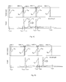
- FIGS. 7A-7E generation of a multi-laser swept signal is depicted.
- the top of each of FIGS. 7A-7E demonstrates the transmission of the range blocking components at different wavelengths.
- the sharp decrease in transmission of the wavelength blocking components represent the wavelength blocking wavelengths of the different wavelength blocking components.
- the bottom of each of FIGS. 7A-7E represent the wavelength of the output ⁇ 1 , ⁇ 3 , ⁇ 3 of each laser source 112 , 113 , 114 .
- Generation of the multi-laser swept signal may be accomplished according to the steps outlined in FIG. 4 or 5 .
- each of the first laser source 112 , the second laser source 113 , and the third laser source 114 are parked at their respective end wavelengths ⁇ end1 , ⁇ end2 , ⁇ end3 .
- the first laser source 112 is swept from the first start wavelength ⁇ start1 to the first end wavelength ⁇ end1 , while the second laser source 113 and the third laser source 114 are parked at the second start wavelength ⁇ start2 and third start wavelength ⁇ start3 respectively.
- the output of the second laser source 113 and third laser source 114 are blocked by the third wavelength blocking component 117 and fifth wavelength blocking component 118 respectively such that the output of the system 100 is approximately equal to the output of the first laser source 112 .
- the output of the first laser source 112 is blocked by the second wavelength blocking component 120 and the second laser source 113 is swept from the second start wavelength ⁇ start2 along its wavelength working range ⁇ range2 such that the output of the second laser source 113 is no longer blocked by the third wavelength blocking component 117 .
- the output of the first laser source 112 and third laser source 114 are blocked by the second wavelength blocking component 120 and fifth wavelength blocking component 118 respectively such that the output of the system 100 is approximately equal to the output of the second laser source 113 .
- the output of the second laser source 113 is blocked by the fourth wavelength blocking component 122 and the third laser source 114 is swept from the third start wavelength ⁇ start3 along its wavelength working range ⁇ range3 such that the output of the third laser source 114 is no longer blocked by the fifth wavelength blocking component 118 .
- the output of the first laser source 112 and second laser source 113 are blocked by the second wavelength blocking component 120 and fourth wavelength blocking component 122 respectively such that the output of the system 100 is approximately equal to the output of the third laser source 114 .
- the third laser source 114 reaches the third end wavelength ⁇ end3 , and the output of the third laser source 114 is blocked by the sixth wavelength blocking component 124 .
- the output of the first laser source 112 , second laser source 113 , and third laser source 114 are blocked by the second wavelength blocking component 120 , fourth wavelength blocking component 122 , and sixth wavelength blocking component 124 respectively such that there is approximately no output from the system 100 .
Landscapes
- Physics & Mathematics (AREA)
- Condensed Matter Physics & Semiconductors (AREA)
- General Physics & Mathematics (AREA)
- Electromagnetism (AREA)
- Optics & Photonics (AREA)
- Semiconductor Lasers (AREA)
Abstract
Description
Claims (24)
Priority Applications (1)
| Application Number | Priority Date | Filing Date | Title |
|---|---|---|---|
| US14/211,593 US9502860B1 (en) | 2013-03-15 | 2014-03-14 | Eliminating unwanted optical output power from a multi-device tunable laser by using a wavelength blocking component |
Applications Claiming Priority (2)
| Application Number | Priority Date | Filing Date | Title |
|---|---|---|---|
| US201361786975P | 2013-03-15 | 2013-03-15 | |
| US14/211,593 US9502860B1 (en) | 2013-03-15 | 2014-03-14 | Eliminating unwanted optical output power from a multi-device tunable laser by using a wavelength blocking component |
Publications (1)
| Publication Number | Publication Date |
|---|---|
| US9502860B1 true US9502860B1 (en) | 2016-11-22 |
Family
ID=57287796
Family Applications (1)
| Application Number | Title | Priority Date | Filing Date |
|---|---|---|---|
| US14/211,593 Expired - Fee Related US9502860B1 (en) | 2013-03-15 | 2014-03-14 | Eliminating unwanted optical output power from a multi-device tunable laser by using a wavelength blocking component |
Country Status (1)
| Country | Link |
|---|---|
| US (1) | US9502860B1 (en) |
Cited By (1)
| Publication number | Priority date | Publication date | Assignee | Title |
|---|---|---|---|---|
| JP2021189243A (en) * | 2020-05-27 | 2021-12-13 | 株式会社デンソー | Beam deflection system |
Citations (5)
| Publication number | Priority date | Publication date | Assignee | Title |
|---|---|---|---|---|
| US5659644A (en) * | 1996-06-07 | 1997-08-19 | Lucent Technologies Inc. | Fiber light source with multimode fiber coupler |
| US5841797A (en) * | 1994-06-28 | 1998-11-24 | Ventrudo; Brian F. | Apparatus for stabilizing multiple laser sources and their application |
| US20010036332A1 (en) * | 2000-04-11 | 2001-11-01 | 3M Innovative Properties Company | Method and apparatus for generating frequency modulated pulses |
| US6480513B1 (en) * | 2000-10-03 | 2002-11-12 | K2 Optronics, Inc. | Tunable external cavity laser |
| US20030039015A1 (en) * | 2000-06-16 | 2003-02-27 | Sri International | Reconfigurable multi-channel transmitter for dense wavelength division multiplexing (DWDM) optical communications |
-
2014
- 2014-03-14 US US14/211,593 patent/US9502860B1/en not_active Expired - Fee Related
Patent Citations (5)
| Publication number | Priority date | Publication date | Assignee | Title |
|---|---|---|---|---|
| US5841797A (en) * | 1994-06-28 | 1998-11-24 | Ventrudo; Brian F. | Apparatus for stabilizing multiple laser sources and their application |
| US5659644A (en) * | 1996-06-07 | 1997-08-19 | Lucent Technologies Inc. | Fiber light source with multimode fiber coupler |
| US20010036332A1 (en) * | 2000-04-11 | 2001-11-01 | 3M Innovative Properties Company | Method and apparatus for generating frequency modulated pulses |
| US20030039015A1 (en) * | 2000-06-16 | 2003-02-27 | Sri International | Reconfigurable multi-channel transmitter for dense wavelength division multiplexing (DWDM) optical communications |
| US6480513B1 (en) * | 2000-10-03 | 2002-11-12 | K2 Optronics, Inc. | Tunable external cavity laser |
Cited By (1)
| Publication number | Priority date | Publication date | Assignee | Title |
|---|---|---|---|---|
| JP2021189243A (en) * | 2020-05-27 | 2021-12-13 | 株式会社デンソー | Beam deflection system |
Similar Documents
| Publication | Publication Date | Title |
|---|---|---|
| US11457132B2 (en) | Imaging using optical cavity | |
| US10018725B2 (en) | LIDAR imaging system | |
| US10426336B2 (en) | Optical coherence tomography system combining two wavelengths | |
| US20070098028A1 (en) | Laser systems | |
| JP2010536164A5 (en) | ||
| CN105911535B (en) | Wavelength-division multiplex detection system similar in a kind of laser radar multi-wavelength | |
| US10401483B2 (en) | Distance measuring device and method for determining a distance | |
| KR102099935B1 (en) | Time of flight camera apparatus | |
| JP2015524047A5 (en) | ||
| US20170153458A1 (en) | Optical module | |
| CN105917535A (en) | Semiconductor laser device | |
| CN110300907A (en) | Equipment and its generation method and spectrometer system for optical application | |
| US9502860B1 (en) | Eliminating unwanted optical output power from a multi-device tunable laser by using a wavelength blocking component | |
| US8724667B2 (en) | System and method for multiple laser sources using high semiconductor optical amplifier extinction | |
| CN114252865A (en) | System and method for pre-blinding a LIDAR detector | |
| US11808659B2 (en) | Parallel optics based optical time domain reflectometer acquisition | |
| US9818009B2 (en) | Multi-spectral enhancements for scan cameras | |
| CN104122237A (en) | Gene sequencing optical system | |
| RU2015132844A (en) | POWERFUL PULSE CO2 LASER WITH SELF-INJECTION OF RADIATION | |
| CN116057414A (en) | Mirrors with polarizing beam splitters for LIDAR systems | |
| US9246304B2 (en) | Pulse shaping device and pulse shaping method | |
| CN109373933B (en) | Device and method for detecting verticality of diffraction grating | |
| US10374384B2 (en) | Laser feedback control systems | |
| WO2020097456A1 (en) | Lidar sensor with attenuating element | |
| EP3786606A1 (en) | Parallel optics based optical time domain reflectometer acquisition |
Legal Events
| Date | Code | Title | Description |
|---|---|---|---|
| AS | Assignment |
Owner name: INSIGHT PHOTONIC SOLUTIONS, INC., COLORADO Free format text: ASSIGNMENT OF ASSIGNORS INTEREST;ASSIGNOR:MINNEMAN, MICHAEL;REEL/FRAME:032647/0116 Effective date: 20140225 |
|
| ZAAA | Notice of allowance and fees due |
Free format text: ORIGINAL CODE: NOA |
|
| ZAAB | Notice of allowance mailed |
Free format text: ORIGINAL CODE: MN/=. |
|
| STCF | Information on status: patent grant |
Free format text: PATENTED CASE |
|
| AS | Assignment |
Owner name: DEEPTECH DISRUPTIVE GROWTH INVESTMENTS LTD, ENGLAN Free format text: SECURITY INTEREST;ASSIGNOR:INSIGHT PHOTONIC SOLUTIONS, INC.;REEL/FRAME:046655/0554 Effective date: 20180726 |
|
| AS | Assignment |
Owner name: SAXUM COMPANY, RLLLP, COLORADO Free format text: SECURITY INTEREST;ASSIGNOR:INSIGHT PHOTONIC SOLUTIONS, INC.;REEL/FRAME:046956/0864 Effective date: 20180924 |
|
| AS | Assignment |
Owner name: WAYMO LLC, CALIFORNIA Free format text: SECURITY INTEREST;ASSIGNOR:INSIGHT PHOTONIC SOLUTIONS, INC.;REEL/FRAME:050091/0099 Effective date: 20190816 |
|
| AS | Assignment |
Owner name: INSIGHT PHOTONIC SOLUTIONS, INC., COLORADO Free format text: RELEASE BY SECURED PARTY;ASSIGNOR:DEEPTECH DISRUPTIVE GROWTH INVESTMENTS LTD;REEL/FRAME:051115/0785 Effective date: 20190812 |
|
| MAFP | Maintenance fee payment |
Free format text: PAYMENT OF MAINTENANCE FEE, 4TH YR, SMALL ENTITY (ORIGINAL EVENT CODE: M2551); ENTITY STATUS OF PATENT OWNER: SMALL ENTITY Year of fee payment: 4 |
|
| AS | Assignment |
Owner name: SAXUM COMPANY, RLLLP, COLORADO Free format text: SECURITY INTEREST;ASSIGNORS:INSIGHT PHOTONIC SOLUTIONS, INC.;INSIGHT LIDAR;REEL/FRAME:062540/0894 Effective date: 20230123 |
|
| FEPP | Fee payment procedure |
Free format text: MAINTENANCE FEE REMINDER MAILED (ORIGINAL EVENT CODE: REM.); ENTITY STATUS OF PATENT OWNER: SMALL ENTITY |
|
| LAPS | Lapse for failure to pay maintenance fees |
Free format text: PATENT EXPIRED FOR FAILURE TO PAY MAINTENANCE FEES (ORIGINAL EVENT CODE: EXP.); ENTITY STATUS OF PATENT OWNER: SMALL ENTITY |
|
| STCH | Information on status: patent discontinuation |
Free format text: PATENT EXPIRED DUE TO NONPAYMENT OF MAINTENANCE FEES UNDER 37 CFR 1.362 |
|
| FP | Lapsed due to failure to pay maintenance fee |
Effective date: 20241122 |