US9500268B2 - Locking differential assembly - Google Patents
Locking differential assembly Download PDFInfo
- Publication number
- US9500268B2 US9500268B2 US14/559,075 US201414559075A US9500268B2 US 9500268 B2 US9500268 B2 US 9500268B2 US 201414559075 A US201414559075 A US 201414559075A US 9500268 B2 US9500268 B2 US 9500268B2
- Authority
- US
- United States
- Prior art keywords
- locking
- dog
- differential
- teeth
- apertures
- Prior art date
- Legal status (The legal status is an assumption and is not a legal conclusion. Google has not performed a legal analysis and makes no representation as to the accuracy of the status listed.)
- Active, expires
Links
Images


Classifications
-
- F—MECHANICAL ENGINEERING; LIGHTING; HEATING; WEAPONS; BLASTING
- F16—ENGINEERING ELEMENTS AND UNITS; GENERAL MEASURES FOR PRODUCING AND MAINTAINING EFFECTIVE FUNCTIONING OF MACHINES OR INSTALLATIONS; THERMAL INSULATION IN GENERAL
- F16H—GEARING
- F16H48/00—Differential gearings
-
- F—MECHANICAL ENGINEERING; LIGHTING; HEATING; WEAPONS; BLASTING
- F16—ENGINEERING ELEMENTS AND UNITS; GENERAL MEASURES FOR PRODUCING AND MAINTAINING EFFECTIVE FUNCTIONING OF MACHINES OR INSTALLATIONS; THERMAL INSULATION IN GENERAL
- F16H—GEARING
- F16H48/00—Differential gearings
- F16H48/20—Arrangements for suppressing or influencing the differential action, e.g. locking devices
- F16H48/24—Arrangements for suppressing or influencing the differential action, e.g. locking devices using positive clutches or brakes
-
- F—MECHANICAL ENGINEERING; LIGHTING; HEATING; WEAPONS; BLASTING
- F16—ENGINEERING ELEMENTS AND UNITS; GENERAL MEASURES FOR PRODUCING AND MAINTAINING EFFECTIVE FUNCTIONING OF MACHINES OR INSTALLATIONS; THERMAL INSULATION IN GENERAL
- F16H—GEARING
- F16H48/00—Differential gearings
- F16H48/20—Arrangements for suppressing or influencing the differential action, e.g. locking devices
-
- F—MECHANICAL ENGINEERING; LIGHTING; HEATING; WEAPONS; BLASTING
- F16—ENGINEERING ELEMENTS AND UNITS; GENERAL MEASURES FOR PRODUCING AND MAINTAINING EFFECTIVE FUNCTIONING OF MACHINES OR INSTALLATIONS; THERMAL INSULATION IN GENERAL
- F16H—GEARING
- F16H48/00—Differential gearings
- F16H48/38—Constructional details
- F16H48/40—Constructional details characterised by features of the rotating cases
-
- F—MECHANICAL ENGINEERING; LIGHTING; HEATING; WEAPONS; BLASTING
- F16—ENGINEERING ELEMENTS AND UNITS; GENERAL MEASURES FOR PRODUCING AND MAINTAINING EFFECTIVE FUNCTIONING OF MACHINES OR INSTALLATIONS; THERMAL INSULATION IN GENERAL
- F16H—GEARING
- F16H48/00—Differential gearings
- F16H48/06—Differential gearings with gears having orbital motion
- F16H48/08—Differential gearings with gears having orbital motion comprising bevel gears
-
- F—MECHANICAL ENGINEERING; LIGHTING; HEATING; WEAPONS; BLASTING
- F16—ENGINEERING ELEMENTS AND UNITS; GENERAL MEASURES FOR PRODUCING AND MAINTAINING EFFECTIVE FUNCTIONING OF MACHINES OR INSTALLATIONS; THERMAL INSULATION IN GENERAL
- F16H—GEARING
- F16H48/00—Differential gearings
- F16H48/20—Arrangements for suppressing or influencing the differential action, e.g. locking devices
- F16H48/30—Arrangements for suppressing or influencing the differential action, e.g. locking devices using externally-actuatable means
- F16H48/34—Arrangements for suppressing or influencing the differential action, e.g. locking devices using externally-actuatable means using electromagnetic or electric actuators
Definitions
- the present disclosure relates to a locking differential assembly.
- a differential assembly includes a differential case and a differential gearset with a pair of side gears that are driven by the differential case.
- One type of differential assembly is known as a locking differential assembly and is configured to selectively lock one or both of the output side gears of the differential gearset to the differential case for common rotation about a rotary axis.
- the locking differential assembly includes a locking dog that is non-rotatably but slidably mounted to the differential case so as to be movable into a position where it engages one of the side gears so as to inhibit rotation of the side gear relative to the differential case. While this configuration is well suited for its intended purpose, this type of locking differential assembly is nevertheless susceptible to improvement.
- the present disclosure provides a locking differential assembly with a differential case, a differential gearset and a locking mechanism.
- the differential case has a first case member and a second case member that cooperate to define a cavity.
- the first case member has a first end wall 68 .
- the differential gearset is received in the cavity and has a first side gear.
- the locking mechanism has a plurality of lock apertures, a first locking dog, and a second locking dog.
- the lock apertures are formed in the first end wall 68 .
- the first locking dog has a set of first dog teeth that are fixedly coupled to the first side gear.
- the second locking dog has an annular body, a set of second dog teeth and a plurality of locking tabs.
- the set of second dog teeth extend from the annular body and are configured to be engaged with the set of first dog teeth to inhibit relative rotation between the first and second locking dogs.
- the locking tabs extend radially outwardly from the annular body and are received in the lock apertures.
- the second locking dog are movable along an axis between a first position, in which the set of second dog teeth is disengaged from the set of first dog teeth to permit relative rotation between the first side gear the differential case, and a second position in which the set of second dog teeth is engaged with the set of first dog teeth to inhibit relative rotation between the first side gear and the differential case.
- the lock apertures have a first locking surface that is at least partly frusto-conically shaped.
- the locking tabs define a second locking surface that is configured to matingly engage the first locking surface.
- the present disclosure provides a method for forming a locking differential assembly.
- the method includes: providing a first case member that is configured to be rotatable about a rotary axis, the first case member having a plurality of locking apertures, each of the locking apertures defining a first locking surface with a frusto-conical shape; installing a locking dog to the first case member, the locking dog having a body, a set of first locking teeth, and a plurality of locking tabs, the set of first locking teeth extending axially from the body, the locking tabs extending radially from the body and being received into the locking apertures, the locking tabs defining a second locking surface and being received into the locking apertures, at least a portion of the second locking surface being frusto-conically shaped and configured to matingly engage the first locking surface; and installing a differential gearset to the first case member, the differential gearset having a side gear with a set of second locking teeth that are configured to selectively matingly engage the set of
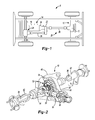
- FIG. 1 is a schematic illustration of a vehicle having a rear axle assembly with an exemplary locking differential assembly constructed in accordance with the teachings of the present disclosure
- FIG. 2 is a perspective view of the rear axle assembly of FIG. 1 ;
- FIG. 3 is an exploded perspective view of a portion of the rear axle assembly, illustrating the locking differential assembly in more detail;
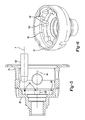
- FIG. 4 is a longitudinal section view of the locking differential assembly
- FIG. 5 is a longitudinal section view of a portion of the locking differential assembly illustrating a first case member in more detail
- FIG. 6 is a perspective, partly broken-away view of the first case member illustrating locking apertures formed in the first case member;
- FIG. 7 is a side elevation of a portion of the locking differential assembly illustrating a second locking dog in more detail
- FIG. 8 is a perspective view of a portion of the second locking dog, illustrating a locking tab formed on an annular body of the second locking dog;
- FIG. 9 is a section view of a portion of the locking differential assembly illustrating contact between a first locking surface, which is formed on the differential case, and a second locking surface that is formed on the locking tab of the second locking dog.
- a vehicle 8 is schematically illustrated as having a rear axle assembly 10 with a locking differential assembly 12 constructed in accordance with the teachings of the present disclosure.
- the vehicle 8 is a four-wheel drive vehicle having a powertrain 14 with an engine 16 and a transmission 18 that provide rotary power to a drivetrain 20 having a transfer case 22 , the rear axle assembly 10 and a front axle assembly 24 .
- Rotary power can be transmitted from the transfer case 22 to the rear axle assembly 10 and the front axle assembly 24 via rear and front propshafts 26 and 28 , respectively.
- the configuration of the front axle assembly 24 can be generally similar to that of the rear axle assembly 10 and as such, a discussion of the rear axle assembly 10 will suffice for the front axle assembly 24 .
- the rear axle assembly 10 is illustrated as including an axle housing assembly 30 , an input pinion 32 , a ring gear 34 , the locking differential assembly 12 , and a pair of axle shafts 36 .
- the axle housing assembly 30 can be any type of housing assembly, such as a Banjo-type axle housing assembly, but in the particular example provided, the axle housing assembly 30 is a Salisbury-type axle housing assembly having a carrier housing 40 and a pair of axle tubes 42 that are coupled to the carrier housing 40 in a conventional and well known manner.
- the carrier housing 40 can define a cavity 44 into which the locking differential assembly 12 is received.
- the input pinion 32 can be mounted to the carrier housing 40 for rotation about a first axis 50 .
- the input pinion 32 can include a pinion gear 52 that can be disposed in the cavity 44 .
- the ring gear 34 can be received in the cavity 44 and rotatable about a second axis 54 that can be transverse or generally perpendicular to the first axis 50 .
- the ring gear 34 can be meshingly engaged to the pinion gear 52 .
- the locking differential assembly 12 can include a differential case 60 , a differential gearset 62 , and a locking mechanism 64 .
- the differential case 60 can be formed as one or more discrete components and can define a differential cavity 66 that can be bounded on opposite sides by first and second end walls 68 and 70 , respectively.
- the differential case 60 is an assembly that is formed of first and second case members 74 and 76 that are bolted to one another and the ring gear 34 .
- the differential case 60 can be mounted to the axle housing assembly 30 for rotation about a second axis 54 , which can be transverse or perpendicular to the first axis 50 .
- the differential gearset 62 can be any type of gearset that can receive rotary power from the differential case 60 and output rotary power to the axle shafts 36 .
- the differential gearset 62 comprises bevel gearing (i.e., two or more bevel pinions 78 that are meshingly engaged with first and second (bevel) side gears 80 and 82 ), but it will be appreciated that other types of gear arrangements, such as spur or helical gear arrangements, could be employed in the alternative.
- the differential gearset 62 can include a pair of output members, i.e., the first and second side gears 80 and 82 , that can be drivingly coupled to the axle shafts 36 in a conventional manner.
- the locking mechanism 64 can comprise a plurality of lock apertures 90 , a first locking dog 92 , a second locking dog 94 and an actuator 96 .
- the lock apertures 90 can be formed in the first end wall 68 and can define a first locking surface 100 that is at least partly frusto-conically shaped.
- Each of the lock apertures 90 can be formed by a rotary cutting tool 102 , such as an end mill, a drill or reamer, when the rotary cutting tool 102 is plunged into the first case member 74 along an axis A that is parallel to the second axis 54 .
- all of the lock apertures 90 extend completely through the first end wall 68 , but those of skill in the art will appreciate that some or all of the lock apertures 90 could be formed in a blind manner so that they are bounded on one side by the first end wall 68 .
- the first locking dog 92 comprises a set of first dog teeth 110 that are fixedly coupled to the first side gear 80 .
- the first dog teeth 110 can be disposed on an outboard lateral side of the first side gear 80 and can be spaced circumferentially about the second axis 54 .
- the second locking dog 94 can have an annular body 118 , a set of second dog teeth 120 and a plurality of locking tabs 122 .
- the set of second dog teeth 120 can extend from the annular body 118 and can be configured to be engaged with the set of first dog teeth 110 to inhibit relative rotation between the first and second locking dogs 92 and 94 .
- the locking tabs 122 can be fixedly coupled to the annular body 118 and can extend radially outwardly there from. Each of the locking tabs 122 can be received in a corresponding one of the lock apertures 90 .
- the locking tabs 122 and the lock apertures 90 can cooperate to limit rotation of the second locking dog 94 relative to the differential case 60 , while permitting movement of the second locking dog 94 along the second axis 54 relative to the differential case 60 .
- the second locking dog 94 can be movable along the second axis 54 between a first position, in which the set of second dog teeth 120 is disengaged from the set of first dog teeth 110 to permit relative rotation between the first side gear 80 the differential case 60 , and a second position in which the set of second dog teeth 120 is engaged with the set of first dog teeth 110 to inhibit relative rotation between the first side gear 80 and the differential case 60 .
- each of the locking tabs 122 can define a second locking surface 130 that is at least partly frusto-conically shaped in a manner that is configured to matingly or correspondingly engage the first locking surface 100 .
- the lock apertures 90 can be sized somewhat larger than the locking tabs 122 so that some relatively small amount of rotation of the second locking dog 94 about the second axis 54 relative to the differential case 60 is permitted over at least a portion of the stroke or travel of the second locking dog 94 that includes the second position of the second locking dog 94 .
- the actuator 96 can be any type of device that can be employed to selectively translate the second locking dog 94 along the second axis 54 .
- Actuators for translating a component of a locking mechanism relative to a differential case are well known in the art and include actuators found in U.S. Pat. Nos. 6,083,134, 6,460,677, 6,958,030, 7,211,020, 7,325,664, 7,399,248 and 7,425,185.
- the actuator 96 comprises an annular solenoid 140 , a thrust plate 142 , and a return spring 144 .
- the annular solenoid 140 can be mounted on the differential case 60 in a manner that permits rotation of the differential case 60 relative to the annular solenoid 140 but which limits movement of the annular solenoid 140 along the second axis 54 in a direction away from the second locking dog 94 .
- the annular solenoid 140 can include an electromagnetic coil 150 and an annular plunger 152 that can be selectively moved along the second axis 54 in response to energization of the electromagnetic coil 150 .
- the thrust plate 142 can be fixedly coupled to the second locking dog 94 .
- the thrust plate 142 is formed of a plastic material that is overmolded (i.e., cohesively bonded) to the second locking dog 94 .
- the thrust plate 142 can include a plurality of legs 158 that can extend from second locking dog 94 on a side opposite the set of second locking teeth 120 .
- Each of the legs 158 can extend into an associated one of the lock apertures 90 and can abut a corresponding one of the locking tabs 122 .
- the return spring 144 can be configured to bias the second locking dog 94 away from the first locking dog 92 so that the set of second dog teeth 120 are normally disengaged from the set of first dog teeth 110 .
- the return spring 144 is disposed between the first and second locking dogs 92 and 94 .
- the locking differential assembly 12 can be operated in a first mode, in which the actuator 96 places the second locking dog 94 in the first position so that the set of second dog teeth 120 are disengaged from the set of first dog teeth 110 .
- the first side gear 80 is permitted to rotate relative to the differential case 60 so that the locking differential assembly 12 operates as an open differential that permits speed differentiation between the first and second side gears 80 and 82 .
- the locking differential assembly 12 can also be operated in a second mode, in which the actuator 96 places the second locking dog 94 in the second position so that the set of second dog teeth 120 are engaged to the set of first dog teeth 110 .
- the first side gear 80 is locked to the differential case 60 for common rotation so that the locking differential assembly 12 operated as a locked differential that does not permit speed differentiation between the first and second side gears 80 and 82 .
- the transmission of torque through the sets of first and second dog teeth 110 and 120 can tend to urge the second locking dog 94 along the second axis 54 away from the first locking dog 92 , which may tend to reduce the amount of contact between the sets of first and second dog teeth 110 and 120 , particularly when the set of first locking teeth 100 are net formed via forging so as to be somewhat tapered.
- the sizing and generally frusto-conical configuration of the first and second locking surfaces 100 and 130 permit limited rotation of the second locking dog 94 relative to the differential case 60 as torque is transmitted between the second locking dog 94 and the differential case 60 .
- first and second locking surfaces 100 and 130 cooperate to generate a force on the locking tabs 122 that tends to drive the second locking dog 94 along the second axis toward the first locking dog 92 .
- first and second locking surfaces 100 and 130 can be contoured or tapered in a desired manner so that a magnitude of the portion of the force that is directed along the second axis 54 can be tailored in a desired manner. For example, a relatively smaller cone angle (used to create the first and second locking surfaces 100 and 130 ) would produce force having an axially directed component that was relatively lower in magnitude, whereas a relatively larger cone angle would produce a force having an axially directed component that was relatively higher in magnitude.
- the cone angle was selected to produce a force having an axially directed component with a magnitude that was about equal to the force that is generated by the meshing of the first and second dog teeth 110 and 120 (to urge the second locking dog 94 away from the first locking dog 92 ) when rotary power of a predetermined magnitude and a predetermined rotational direction is transmitted between the first and second locking dogs 92 and 94 .
- Configuration of the differential case 60 and the second locking dog 94 in this manner is advantageous in that the sets of first and second dog teeth 110 and 120 can be formed without back taper.
- the set of second dog teeth 120 can be formed such that the sides of each tooth can lie in a pair of parallel planes that can be parallel to the second axis 54 .
- One suitable method for forming the set of second dog teeth 110 in this manner include fine blanking.
- the second locking dog 94 could be formed almost in its entirety through fine blanking, and a secondary operation, such as milling or coining, could be employed to form the second locking surfaces 100 .
- a notch 164 can be formed in each of the locking tabs 122 to improve the mechanical connection between the locking tabs 122 and the thrust plate 142 in instances where the thrust plate 142 is overmolded onto the locking tabs 122 .
Landscapes
- Engineering & Computer Science (AREA)
- General Engineering & Computer Science (AREA)
- Mechanical Engineering (AREA)
- Retarders (AREA)
Abstract
Description
Claims (14)
Priority Applications (3)
| Application Number | Priority Date | Filing Date | Title |
|---|---|---|---|
| US14/559,075 US9500268B2 (en) | 2014-12-03 | 2014-12-03 | Locking differential assembly |
| DE102015120707.9A DE102015120707B4 (en) | 2014-12-03 | 2015-11-30 | Limited-slip differential assembly with partially frustoconical locking tongues |
| CN201510881702.XA CN105673801B (en) | 2014-12-03 | 2015-12-03 | locking differential assembly |
Applications Claiming Priority (1)
| Application Number | Priority Date | Filing Date | Title |
|---|---|---|---|
| US14/559,075 US9500268B2 (en) | 2014-12-03 | 2014-12-03 | Locking differential assembly |
Publications (2)
| Publication Number | Publication Date |
|---|---|
| US20160160981A1 US20160160981A1 (en) | 2016-06-09 |
| US9500268B2 true US9500268B2 (en) | 2016-11-22 |
Family
ID=55975023
Family Applications (1)
| Application Number | Title | Priority Date | Filing Date |
|---|---|---|---|
| US14/559,075 Active 2035-06-03 US9500268B2 (en) | 2014-12-03 | 2014-12-03 | Locking differential assembly |
Country Status (3)
| Country | Link |
|---|---|
| US (1) | US9500268B2 (en) |
| CN (1) | CN105673801B (en) |
| DE (1) | DE102015120707B4 (en) |
Cited By (5)
| Publication number | Priority date | Publication date | Assignee | Title |
|---|---|---|---|---|
| US10663052B2 (en) | 2018-08-22 | 2020-05-26 | American Axle & Manufacturing, Inc. | Vehicle driveline having a vehicle driveline component with a dual disconnecting differential |
| US10982750B2 (en) | 2018-10-01 | 2021-04-20 | Dana Automotive Systems Group, Llc | Retention system |
| US11142067B2 (en) | 2017-05-09 | 2021-10-12 | Dana Automotive Systems Group, Llc | Differential sensor apparatus and method of use |
| WO2022217355A1 (en) * | 2021-04-16 | 2022-10-20 | Magna Powertrain, Inc. | Disconnecting differential side gear mechanism |
| US11761524B2 (en) | 2021-09-20 | 2023-09-19 | American Axle & Manufacturing, Inc. | Electronic locking differential |
Families Citing this family (7)
| Publication number | Priority date | Publication date | Assignee | Title |
|---|---|---|---|---|
| JP6539783B2 (en) * | 2016-06-01 | 2019-07-03 | Gknドライブラインジャパン株式会社 | Clutch with Cap for Helical LSD |
| US10391861B2 (en) * | 2016-07-27 | 2019-08-27 | American Axle & Manufacturing, Inc. | Axle assembly with disconnecting differential output |
| WO2019141512A1 (en) * | 2018-01-20 | 2019-07-25 | Eaton Intelligent Power Limited | Locking differential assembly |
| US11346432B2 (en) * | 2018-03-07 | 2022-05-31 | Eaton Intelligent Power Limited | Electrically controlled automatic locker differential |
| JP6498855B1 (en) * | 2019-01-21 | 2019-04-10 | 株式会社ショーワ | Differential gear and differential gear |
| CN110145584B (en) * | 2019-05-29 | 2022-02-25 | 精诚工科汽车系统有限公司 | Differential mechanism assembly and vehicle |
| MX2023010920A (en) | 2021-03-16 | 2023-10-23 | American Axle & Mfg Inc | Disconnecting electric drive unit. |
Citations (5)
| Publication number | Priority date | Publication date | Assignee | Title |
|---|---|---|---|---|
| US3105394A (en) * | 1960-12-27 | 1963-10-01 | Salzmann Willi Ernst | Differential gear with locking means |
| US5749803A (en) | 1995-09-13 | 1998-05-12 | Tochigi Fuji Sangyo Kabushiki Kaisha | Differential apparatus |
| US7445575B2 (en) * | 2004-08-04 | 2008-11-04 | American Axle & Manufacturing, Inc. | Positive clutch with staggered teeth height |
| US8167764B2 (en) | 2009-06-04 | 2012-05-01 | American Axle & Manufacturing, Inc. | Locking power transmitting device |
| US20150204431A1 (en) * | 2013-01-23 | 2015-07-23 | Eaton Corporation | Locking differential assembly |
Family Cites Families (9)
| Publication number | Priority date | Publication date | Assignee | Title |
|---|---|---|---|---|
| DE19716386C2 (en) * | 1996-04-19 | 2002-10-31 | Tochigi Fuji Sangyo Kk | differential |
| US6083134A (en) | 1999-02-18 | 2000-07-04 | Eaton Corporation | Electronically actuated locking differential |
| US6551209B2 (en) * | 2000-01-18 | 2003-04-22 | Eaton Corporation | Electronically actuated locking differential |
| US6460677B1 (en) | 2000-11-28 | 2002-10-08 | Spicer Technology, Inc. | Dual ball ramp actuator for locking differential |
| US6958030B2 (en) | 2003-09-29 | 2005-10-25 | American Axle & Manufacturing, Inc. | Electromagnetic locking differential assembly |
| US7325664B2 (en) | 2004-06-16 | 2008-02-05 | Tochigi Fuji Sangyo Kabushiki Kaisha | Electromagnetic actuator, and electromagnetic clutch and differential using the same |
| US7211020B2 (en) | 2005-05-26 | 2007-05-01 | American Axle & Manufacturing, Inc. | Lockable differential with locking state detection system |
| US7399248B2 (en) | 2006-05-22 | 2008-07-15 | Ford Motor Company | Moving coil electronic locking differential |
| US7602271B2 (en) * | 2006-08-21 | 2009-10-13 | American Axle & Manufacturing, Inc. | Electronically actuated apparatus using solenoid actuator with integrated sensor |
-
2014
- 2014-12-03 US US14/559,075 patent/US9500268B2/en active Active
-
2015
- 2015-11-30 DE DE102015120707.9A patent/DE102015120707B4/en active Active
- 2015-12-03 CN CN201510881702.XA patent/CN105673801B/en active Active
Patent Citations (5)
| Publication number | Priority date | Publication date | Assignee | Title |
|---|---|---|---|---|
| US3105394A (en) * | 1960-12-27 | 1963-10-01 | Salzmann Willi Ernst | Differential gear with locking means |
| US5749803A (en) | 1995-09-13 | 1998-05-12 | Tochigi Fuji Sangyo Kabushiki Kaisha | Differential apparatus |
| US7445575B2 (en) * | 2004-08-04 | 2008-11-04 | American Axle & Manufacturing, Inc. | Positive clutch with staggered teeth height |
| US8167764B2 (en) | 2009-06-04 | 2012-05-01 | American Axle & Manufacturing, Inc. | Locking power transmitting device |
| US20150204431A1 (en) * | 2013-01-23 | 2015-07-23 | Eaton Corporation | Locking differential assembly |
Non-Patent Citations (1)
| Title |
|---|
| Photographs marked up illustrating the Ford Super Duty Electric Locking Differential Mechanism. |
Cited By (7)
| Publication number | Priority date | Publication date | Assignee | Title |
|---|---|---|---|---|
| US11142067B2 (en) | 2017-05-09 | 2021-10-12 | Dana Automotive Systems Group, Llc | Differential sensor apparatus and method of use |
| US10663052B2 (en) | 2018-08-22 | 2020-05-26 | American Axle & Manufacturing, Inc. | Vehicle driveline having a vehicle driveline component with a dual disconnecting differential |
| US10982750B2 (en) | 2018-10-01 | 2021-04-20 | Dana Automotive Systems Group, Llc | Retention system |
| WO2022217355A1 (en) * | 2021-04-16 | 2022-10-20 | Magna Powertrain, Inc. | Disconnecting differential side gear mechanism |
| US12240321B2 (en) * | 2021-04-16 | 2025-03-04 | Magna Powertrain, Inc. | Disconnecting differential side gear mechanism |
| US12352345B1 (en) | 2021-04-16 | 2025-07-08 | Magna Powertrain, Inc. | Disconnecting differential side gear mechanism |
| US11761524B2 (en) | 2021-09-20 | 2023-09-19 | American Axle & Manufacturing, Inc. | Electronic locking differential |
Also Published As
| Publication number | Publication date |
|---|---|
| CN105673801A (en) | 2016-06-15 |
| CN105673801B (en) | 2018-04-27 |
| DE102015120707A1 (en) | 2016-06-09 |
| US20160160981A1 (en) | 2016-06-09 |
| DE102015120707B4 (en) | 2025-04-03 |
Similar Documents
| Publication | Publication Date | Title |
|---|---|---|
| US9500268B2 (en) | Locking differential assembly | |
| US11118666B2 (en) | Axle assembly with disconnecting differential component | |
| EP3197701B1 (en) | Clutch arrangement and drive arrangement comprising a clutch arrangement | |
| US9346354B2 (en) | Disconnecting driveline component | |
| US10663052B2 (en) | Vehicle driveline having a vehicle driveline component with a dual disconnecting differential | |
| US9353852B2 (en) | Actuator coupling mechanism | |
| DE102012100865B4 (en) | Drive arrangement with electric machine and motor vehicle with such a drive arrangement | |
| US9347503B2 (en) | Actuator for a driveline component | |
| DE112010004718T5 (en) | Detachable rear drive axle for longitudinally arranged drive trains | |
| US20150232070A1 (en) | Park lock for drive module | |
| DE102017117063A1 (en) | Compact, electrically driven axle assembly | |
| DE102013215888A1 (en) | Achsdifferenzialgetriebe for a switchable driven vehicle axle of a motor vehicle | |
| DE102019131387A1 (en) | Compact electromagnetic pulse decoupling system | |
| DE102021111895A1 (en) | A vehicle driveline component having a direction reversing mechanism for moving a movable member to change a mode of operation of the vehicle driveline component | |
| DE112017000752T5 (en) | Differential assembly with two-piece carrier and welded crown gear | |
| DE102013108416A1 (en) | Electric drive and method for controlling such an electric drive | |
| DE102017211437A1 (en) | Divider gearbox with oil distribution | |
| DE102015205102A1 (en) | TRANSMISSION TO DISTRIBUTION DISTRIBUTION OF A DRIVE TORQUE | |
| DE112020005045T5 (en) | ELECTRIC DRIVE MODULE WITH TRANSMISSION WITH PARALLEL DOUBLE GEAR PAIRS DISTRIBUTING LOAD TO A FINAL DRIVE GEAR | |
| DE112022008004T5 (en) | Power transmission device for a vehicle | |
| DE102019108183B4 (en) | Transmission device for a motor vehicle with a differential gear of planetary construction | |
| DE102010063729A1 (en) | Gear arrangement for a power tool and power tool | |
| WO2020108745A1 (en) | Powertrain of a motor vehicle |
Legal Events
| Date | Code | Title | Description |
|---|---|---|---|
| AS | Assignment |
Owner name: AMERICAN AXLE & MANUFACTURING, INC., MICHIGAN Free format text: ASSIGNMENT OF ASSIGNORS INTEREST;ASSIGNOR:BALENDA, JOSEPH S., II;REEL/FRAME:034367/0635 Effective date: 20141203 |
|
| STCF | Information on status: patent grant |
Free format text: PATENTED CASE |
|
| AS | Assignment |
Owner name: JPMORGAN CHASE BANK, N.A., AS COLLATERAL AGENT, NE Free format text: SECURITY INTEREST;ASSIGNORS:AMERICAN AXLE & MANUFACTURING, INC.;CLOYES GEAR AND PRODUCTS, INC.;GREDE LLC;AND OTHERS;REEL/FRAME:042734/0001 Effective date: 20170605 Owner name: JPMORGAN CHASE BANK, N.A., AS COLLATERAL AGENT, NEW YORK Free format text: SECURITY INTEREST;ASSIGNORS:AMERICAN AXLE & MANUFACTURING, INC.;CLOYES GEAR AND PRODUCTS, INC.;GREDE LLC;AND OTHERS;REEL/FRAME:042734/0001 Effective date: 20170605 |
|
| MAFP | Maintenance fee payment |
Free format text: PAYMENT OF MAINTENANCE FEE, 4TH YEAR, LARGE ENTITY (ORIGINAL EVENT CODE: M1551); ENTITY STATUS OF PATENT OWNER: LARGE ENTITY Year of fee payment: 4 |
|
| AS | Assignment |
Owner name: JPMORGAN CHASE BANK, N.A., AS COLLATERAL AGENT, NEW YORK Free format text: SECURITY INTEREST;ASSIGNOR:AMERICAN AXLE & MANUFACTURING, INC.;REEL/FRAME:060244/0001 Effective date: 20220525 |
|
| MAFP | Maintenance fee payment |
Free format text: PAYMENT OF MAINTENANCE FEE, 8TH YEAR, LARGE ENTITY (ORIGINAL EVENT CODE: M1552); ENTITY STATUS OF PATENT OWNER: LARGE ENTITY Year of fee payment: 8 |
|
| AS | Assignment |
Owner name: U.S. BANK TRUST COMPANY, NATIONAL ASSOCIATION, AS NOTES COLLATERAL AGENT, MICHIGAN Free format text: SECURITY INTEREST;ASSIGNORS:AMERICAN AXLE MANUFACTURING, INC.;MD INVESTORS CORPORATION;AAM NORTH AMERICA, INC.;REEL/FRAME:073005/0001 Effective date: 20251003 |