US9500172B2 - Starter system - Google Patents
Starter system Download PDFInfo
- Publication number
- US9500172B2 US9500172B2 US13/676,010 US201213676010A US9500172B2 US 9500172 B2 US9500172 B2 US 9500172B2 US 201213676010 A US201213676010 A US 201213676010A US 9500172 B2 US9500172 B2 US 9500172B2
- Authority
- US
- United States
- Prior art keywords
- plunger
- solenoid
- starter
- current
- switch
- Prior art date
- Legal status (The legal status is an assumption and is not a legal conclusion. Google has not performed a legal analysis and makes no representation as to the accuracy of the status listed.)
- Active, expires
Links
- 239000007858 starting material Substances 0.000 title claims abstract description 76
- 238000004804 winding Methods 0.000 claims abstract description 97
- 238000004891 communication Methods 0.000 claims abstract description 7
- 230000008878 coupling Effects 0.000 claims description 31
- 238000010168 coupling process Methods 0.000 claims description 31
- 238000005859 coupling reaction Methods 0.000 claims description 31
- 230000033001 locomotion Effects 0.000 claims description 19
- 230000000712 assembly Effects 0.000 abstract description 7
- 238000000429 assembly Methods 0.000 abstract description 7
- 238000010586 diagram Methods 0.000 description 6
- 230000001360 synchronised effect Effects 0.000 description 4
- 230000008859 change Effects 0.000 description 3
- 230000004048 modification Effects 0.000 description 2
- 238000012986 modification Methods 0.000 description 2
- 230000004044 response Effects 0.000 description 2
- 230000001133 acceleration Effects 0.000 description 1
- 230000003213 activating effect Effects 0.000 description 1
- 230000004913 activation Effects 0.000 description 1
- 238000002485 combustion reaction Methods 0.000 description 1
- 238000010276 construction Methods 0.000 description 1
- 230000009849 deactivation Effects 0.000 description 1
- 230000000881 depressing effect Effects 0.000 description 1
- 238000001514 detection method Methods 0.000 description 1
- 238000005265 energy consumption Methods 0.000 description 1
- 230000002779 inactivation Effects 0.000 description 1
- 230000000717 retained effect Effects 0.000 description 1
- 230000011664 signaling Effects 0.000 description 1
Images


Classifications
-
- F—MECHANICAL ENGINEERING; LIGHTING; HEATING; WEAPONS; BLASTING
- F02—COMBUSTION ENGINES; HOT-GAS OR COMBUSTION-PRODUCT ENGINE PLANTS
- F02N—STARTING OF COMBUSTION ENGINES; STARTING AIDS FOR SUCH ENGINES, NOT OTHERWISE PROVIDED FOR
- F02N11/00—Starting of engines by means of electric motors
- F02N11/08—Circuits specially adapted for starting of engines
- F02N11/0851—Circuits specially adapted for starting of engines characterised by means for controlling the engagement or disengagement between engine and starter, e.g. meshing of pinion and engine gear
-
- F—MECHANICAL ENGINEERING; LIGHTING; HEATING; WEAPONS; BLASTING
- F02—COMBUSTION ENGINES; HOT-GAS OR COMBUSTION-PRODUCT ENGINE PLANTS
- F02N—STARTING OF COMBUSTION ENGINES; STARTING AIDS FOR SUCH ENGINES, NOT OTHERWISE PROVIDED FOR
- F02N11/00—Starting of engines by means of electric motors
- F02N11/08—Circuits specially adapted for starting of engines
- F02N11/087—Details of the switching means in starting circuits, e.g. relays or electronic switches
-
- F—MECHANICAL ENGINEERING; LIGHTING; HEATING; WEAPONS; BLASTING
- F02—COMBUSTION ENGINES; HOT-GAS OR COMBUSTION-PRODUCT ENGINE PLANTS
- F02N—STARTING OF COMBUSTION ENGINES; STARTING AIDS FOR SUCH ENGINES, NOT OTHERWISE PROVIDED FOR
- F02N15/00—Other power-operated starting apparatus; Component parts, details, or accessories, not provided for in, or of interest apart from groups F02N5/00 - F02N13/00
- F02N15/02—Gearing between starting-engines and started engines; Engagement or disengagement thereof
- F02N15/04—Gearing between starting-engines and started engines; Engagement or disengagement thereof the gearing including disengaging toothed gears
- F02N15/06—Gearing between starting-engines and started engines; Engagement or disengagement thereof the gearing including disengaging toothed gears the toothed gears being moved by axial displacement
- F02N15/067—Gearing between starting-engines and started engines; Engagement or disengagement thereof the gearing including disengaging toothed gears the toothed gears being moved by axial displacement the starter comprising an electro-magnetically actuated lever
-
- F—MECHANICAL ENGINEERING; LIGHTING; HEATING; WEAPONS; BLASTING
- F02—COMBUSTION ENGINES; HOT-GAS OR COMBUSTION-PRODUCT ENGINE PLANTS
- F02N—STARTING OF COMBUSTION ENGINES; STARTING AIDS FOR SUCH ENGINES, NOT OTHERWISE PROVIDED FOR
- F02N11/00—Starting of engines by means of electric motors
- F02N11/08—Circuits specially adapted for starting of engines
- F02N2011/0881—Components of the circuit not provided for by previous groups
- F02N2011/0892—Two coils being used in the starting circuit, e.g. in two windings in the starting relay or two field windings in the starter
Definitions
- Some electric machines can play important roles in vehicle operation.
- some vehicles can include a starter, which can, upon a user closing an ignition switch, lead to cranking of engine components of the vehicle.
- Drive train systems capable of frequent start and stop conditions are a further requirement in modern vehicles. Frequent start-stop conditions require the starter to operate at high efficiency both at cold engine crank and warm engine crank environments. The demands of frequent start-stop conditions require various components and systems that function more rapidly and more efficiently to increase reliability, reduce energy consumption and enhance the driving experience.
- Some starters can include a one or more sensor assemblies for detection of various functional components of the start motor, and a control system capable of directing various functional components of the starter system to enable reliable, synchronous engagement.
- Some starter motors can include a field assembly that can produce a magnetic field to rotate some starter motor components.
- Some starter motors can include one or more field assemblies that can produce a magnetic field to translate some starter motor components.
- Some embodiments of the invention provide a starter that can perform well at high-speeds having low torque demand while also operating well at low speeds having high torque demanded of the starter.
- the starter is able to meet the cold crank requirement and function under a warm start scenario while reducing the pinion speed at low pinion torque.
- some embodiments of the invention provide components and systems that are configured and arranged to function to allow better engagement of the starter system with the drivetrain of the vehicle.
- a starter system comprising a starter capable of being controlled by an electronic control unit.
- the starter can include a motor coupled to a circuit, a plurality of solenoid assemblies, and a plunger moveably coupled to a pinion.
- the motor and the plurality of solenoid assemblies is configured and arranged to be capable of being controlled by an electronic control unit.
- the plunger is configured and arranged to be electromagnetically coupled to at least one solenoid assembly.
- a solenoid assembly can include a plunger-return biasing member and at least two solenoid windings at least partially circumscribing the plunger.
- the solenoid windings are configured and arranged to alternately move and to prevent motion of the plunger, and in some embodiments, the resistance of the second set of solenoid windings is greater than the resistance of the first set of solenoid windings.
- the circuit include a first switch capable of actuation by the plunger.
- the first switch comprises at least two contacts capable of electrical coupling with the motor, and is configured and arranged to actuate under the influence of the plunger to either cause current to flow, or to prevent current flow.
- the at least two contacts can couple with a coupling member that is integral to the first switch.
- the coupling member comprises the plunger.
- the movement of the plunger and coupling with the at least two contacts enables the flow of current through the first switch.
- movement of the plunger and decoupling from the contacts prevents the flow of current through the first switch.
- a secondary solenoid assembly comprising a secondary coil winding at least partially circumscribing a secondary plunger, and is configured and arranged to electrically couple with a set of secondary solenoid assembly contacts.
- the secondary solenoid winding can be configured and arranged to move the secondary plunger to couple and decouple with a set of secondary solenoid assembly contacts to control current to flow to the motor.
- the circuit include at least one pin coupled to the circuit capable of controlling a current flow to at least one other component in the circuit under control from an electronic control unit.
- a switch can be further coupled to the circuit.
- the switch can be controlled by an electronic control unit.
- the circuit can include at least one magnetic switch.
- one or more pins can control the flow of current to one or more solenoid windings independently.
- FIG. 1 is a diagram of a machine control system according to one embodiment of the invention.
- FIG. 2 is cross-sectional view of a conventional starter.
- FIG. 3A is circuit diagram representing portions of a starter control system according to one embodiment of the invention.
- FIG. 3B is circuit diagram representing portions of a starter control system according to one embodiment of the invention.
- FIG. 3C is circuit diagram representing portions of a starter control system according to one embodiment of the invention.
- FIG. 4 is a circuit diagram representing portions of a conventional starter control system.
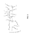
- FIG. 5 is a circuit diagram representing portions of a starter control system according to one embodiment of the invention.
- FIG. 1 illustrates a starter control system 10 according to one embodiment of the invention.
- the system 10 can include an electric machine, a power source 14 , such as a battery, a control module 16 , one or more sensors 18 a and 18 b , and an engine 20 , such as an internal combustion engine.
- a vehicle such as an automobile, can comprise the system 10 , although other vehicles can include the system 10 .
- non-mobile apparatuses such as stationary engines, can comprise the system 10 .
- the starter control system 10 can be used in other starting episodes.
- the control system 10 can be configured and arranged to enable a “stop-start” starting episode.
- the control system 10 can start an engine 20 when the engine 20 has already been started (e.g., during a “cold start” starting episode) and the vehicle continues to be in an active state (e.g., operational), but the engine 20 is automatically temporarily inactivated (e.g., the engine 20 has substantially or completely ceased moving at a stop light).
- control system 10 can be configured and arranged to enable a “change of mind stop-start” starting episode.
- the control system 10 can start an engine 20 when the engine 20 has already been started by a cold start starting episode and the vehicle continues to be in an active state and the engine 20 has been automatically deactivated, but continues to move (i.e., the engine 20 is coasting). For example, after the engine 20 receives a deactivation signal, but before the engine 20 substantially or completely ceases moving, the user can decide to reactivate the engine 20 (i.e.
- the control system 10 can be configured for other starting episodes, such as a conventional “soft start” starting episodes (e.g., the motor 170 is at least partially activated during engagement of the pinion 150 and the ring gear 36 ).
- control system 10 can be employed in other structures for engine 20 starting.
- the control system 10 can be configured and arranged to start the engine 20 during a change of mind stop-start starting episode.
- the engine 20 can be deactivated upon receipt of a signal from the engine control unit 16 (e.g., the vehicle is not moving and the engine 20 speed is at or below idle speed, the engine control unit 16 instructs the engine 20 to inactivate after the vehicle user depresses a brake pedal for a certain duration, etc.), the engine 20 can be deactivated, but the vehicle can remain active (e.g., at least a portion of the vehicle systems can be operated by the power source 14 or in other manners).
- the vehicle user can choose to restart the engine 20 by signaling the engine control unit 16 (e.g., via releasing the brake pedal, depressing the acceleration pedal, etc.) which will cause the pinion 150 to be automatically engaged with the ring gear 36 .
- a speed of the pinion 150 (the pinion speed multiplied by the ring/pinion gear ratio) can be substantially synchronized with a speed of the ring gear 36 (i.e., a speed of the engine 20 ) when the starter 12 attempts to engage the pinion 150 with the ring gear 36 .
- the engine control unit 16 can then use at least some portions of the starter control system 10 to restart the engine 20 .
- the electric machine can comprise a starter 12 .
- the starter 12 can comprise a housing 115 , a gear train 165 , a brushed or brushless motor 170 , a solenoid assembly 125 , an over-running clutch 130 , and a pinion 150 .
- the starter 12 can operate in a generally conventional manner.
- circulation of a current through the solenoid assembly 125 can cause a plunger 135 to move the pinion 150 into an engagement position (e.g., an abutment position and/or an engaged position) with a ring gear 36 of a crankshaft of the engine 20 .
- a signal e.g., a user closing a switch, such as an ignition switch 315
- circulation of a current through the solenoid assembly 125 can cause a plunger 135 to move the pinion 150 into an engagement position (e.g., an abutment position and/or an engaged position) with a ring gear 36 of a crankshaft of the engine 20 .
- the same or another signal can lead to the motor 170 generating an electromotive force, which can be translated through the gear train 165 to the pinion 150 engaged with the ring gear 36 .
- the pinion 150 can crank the engine 20 , which can lead to engine ignition.
- the over-running clutch 130 can aid in reducing a risk of damage to the starter and the motor 170 by disengaging the pinion 150 from a shaft 162 connecting the pinion 150 and the motor 170 (e.g., allowing the pinion 150 to free spin if it is still engaged with the ring gear 36 ).
- the pinion 150 can be directly coupled to a shaft of the motor 170 and can function without a gear train 165 .
- the solenoid assembly 125 can comprise one or more sets of solenoid windings.
- the solenoid assembly 125 can comprise a first set solenoid windings 127 and a second set of solenoid windings 129 .
- the starter 12 e.g., the solenoid assembly 125
- the starter 12 can include a plunger 135 operatively coupled to a shift lever 153 , including a first end 155 and a second end 158 .
- the shift lever 153 can be coupled to the pinion 150 .
- the plunger 135 can be moved (e.g. drawn inward or pushed outward) by at least a portion of the magnetomotive force generated by the windings 127 , 129 and at least a portion of the movement created can be translated to engage of the pinion 150 and the ring gear 36 .
- the first and second sets of solenoid windings 127 , 129 can comprise different functions.
- the first set of solenoid windings 127 can be configured and arranged to move the plunger 135 .
- the plunger 135 can move (e.g., be drawn inward through the first set of solenoid windings 127 ), which can cause the shift lever 153 to move the pinion 150 into engagement with the ring gear 36 .
- the second set of solenoid windings 129 can function to at least partially retain the plunger 135 in a desired position.
- the first set of solenoid windings 127 can function to move the plunger 135 from a first position (e.g., where the plunger 135 is biased via a spring force when little to no current flows through the first or second set of solenoid windings 129 ) to a second position (e.g., where the plunger 135 moves the shift lever 153 to cause the pinion 150 to engage the ring gear 36 ).
- the second set of solenoid windings 129 can also function to move the plunger 135 from the first position to the second position, in lieu of or in addition to the first set of solenoid windings 127 .
- the first set of solenoid windings 127 can be substantially or completely de-energized and the second set of solenoid windings 129 can be energized or remain energized to retain the plunger 135 in the second position.
- the second set of windings 129 can comprise a greater resistance and, as a result, a lesser current relative to the first set of solenoid windings 127 .
- the second set of solenoid windings 129 after the engine 20 has been started, the second set of solenoid windings 129 can be substantially or completely de-energized and a spring force (not shown) can move the plunger 135 back to the first position.
- the circulation of current through the first and second sets of solenoid windings 127 , 129 can cause the plunger 135 to move due to magnetomotive force.
- the solenoid assembly 125 can be configured and arranged so that the plunger 135 is drawn within the first 127 and/or second set of solenoid windings 129 as shown in FIGS. 3A-3C , so that the windings 127 , 129 substantially circumscribe at least a portion of the plunger 135 .
- the plunger 135 can comprise a plurality of sizes (e.g., multiple diameters, etc.)
- a distance between the plunger 135 and the windings 127 , 129 becomes smaller.
- a size of an air gap between the plunger 135 and windings 127 , 129 becomes lesser as the plunger 135 axially moves through the solenoid assembly 125 because portions of the plunger 135 with a greater size (e.g., circumference) pass through windings 127 , 129 as the plunger 135 axially moves.
- lesser amounts of magnetomotive force are necessary to move the plunger 135 as the air gap becomes lesser in size.
- an end portion of the plunger 135 can engage a set of contacts to close a circuit that can route current from the power source 14 to the motor 170 to start the engine 20 (e.g., transfer torque via the pinion 150 to the ring gear 36 ) when the plunger 135 is in the second position.
- the second set of solenoid windings 129 can become at least partially energized to retain the plunger 135 in position (e.g., the second set of solenoid windings 129 can function to hold the plunger 135 in the second position) and/or to complete the movement of the plunger 135 toward the second position.
- the solenoid windings 129 current can continue to flow through the contacts and to the motor 170 , which can lead to starting of the engine 20 , similar to some previously described embodiments.
- the first set of solenoid windings 127 can be at least partially inactivated by movement of the plunger 135 .
- the first set of solenoid windings 127 can be substantially prevented from functioning.
- the plunger 135 can disable (e.g., “short circuit”) the first set of solenoid windings 127 and the second set of solenoid windings 129 can function to retain the plunger 135 in position because of the reduced need for magnetomotive force, as previously mentioned.
- the first and the second sets of solenoid windings 127 , 129 can also be activated and deactivated at the same time.
- the solenoid assembly 125 can comprise multiple configurations. Referring to FIGS. 3A-3C , in some embodiments, at least one of the sets of solenoid windings 127 , 129 can be reversibly coupled to ground through contacts of a first switch 327 . As shown in FIGS. 3A-3C , the first switch 327 is shown as being in between solenoid winding 127 and ground, and is therefore capable of operating as a ground switch, In some other embodiments, the switch 327 could also be placed in between the solenoid winding 127 and the pin P 2 , enabling functions other than operating as a ground switch. For example, as shown in FIGS.
- a contactor or other coupling member 326 can be disposed between two contacts to electrically couple the first set of solenoid windings 127 to ground.
- movement of the plunger 135 toward the second position, via magnetomotive force produced by the solenoid windings 127 , 129 can at least partially move the coupling member 326 that is disposed between the contacts.
- the connection between the first set of solenoid windings 127 and ground, or the connection between the solenoid winding 127 and the pin P 2 can be disrupted, and, accordingly, current will substantially or completely cease flowing through the first set of solenoid windings 127 .
- the first set of solenoid windings 127 cease producing magnetomotive force when the flow of current ceases.
- the second set of solenoid windings 129 can continue to move the plunger 135 and retain the plunger 135 in position after current ceases to flow through the first set of solenoid windings 127 .
- the contactor or coupling member 326 can comprise a spring-loaded configuration that can be free to move in a translational manner, as shown in FIG. 3B or can comprise a spring-loaded configuration that can be free to move in a generally rotational manner (e.g., one portion of the contactor or coupling member 326 can remain substantially stationary and another portion can move), as shown in FIG. 3C .
- the starter 12 can comprise a secondary solenoid assembly 137 , as shown in FIGS. 3 and 5 .
- the secondary solenoid assembly 137 can comprise a portion of the previously-mentioned solenoid assembly 137 , and, in other embodiments, the secondary solenoid assembly 137 can be coupled to the housing 115 and/or other portions of the starter 12 and in electrical communication with other elements of the starter control system 10 , as shown in FIG. 3 .
- the secondary solenoid assembly 137 can comprise one or more magnetic switches.
- the secondary solenoid assembly 137 can comprise a set of secondary solenoid windings 138 and a second plunger 140 and a set of secondary solenoid assembly contacts 139 .
- the second plunger upon passing current through the secondary solenoid windings 138 , the second plunger can move toward the set of secondary solenoid assembly contacts 139 , which, upon engagement with the plunger 140 , can close at least a portion of a circuit to enable current flow to the motor 170 of the starter 12 to begin rotating the motor 170 .
- the solenoid assembly 125 and secondary solenoid assembly 137 can be electrically coupled to the control module 16 .
- the control module 16 can comprise an electronic control module 16 or a microprocessor in communication with the sensors 18 a , 18 b disposed throughout the starter control system.
- the two or more pins e.g., P 1 and P 2 in FIG. 5 can at least partially provide for a gateway for current passing from a current source (e.g., the battery 14 ) when the signals are received from the electronic control module 16 .
- signals can be sent from the electronic control module 16 that a starting event must occur.
- signals from the electronic control module 16 can be energized and current can flow from the current source through the pins P 1 and P 2 to the solenoid assembly 125 and/or the secondary solenoid assembly 137 to function as previously mentioned.
- one or more switches e.g., magnetic switches
- the magnetic switches may be necessary to convert a low power current from the electronic control module 16 (typically less than 4 amps) to a higher power current (typically 20-30 amps) to allow the pins P 1 and P 2 to have enough power to effectively control the solenoid windings 127 , 129 and 138 .
- pin P 1 connects the current source and the secondary solenoid assembly 137 and pin P 2 connects the current source and the first and second sets of solenoid windings 127 , 129 .
- pin P 2 can be configured and arranged for a relatively small current load (e.g., 30 amps) so that the first and second sets of solenoid windings 127 , 129 can receive sufficient current.
- pin P 1 can be configured and arranged for a greater current load (e.g. 40-1000 amps) so that the secondary solenoid assembly 137 can receive sufficient current.
- the first and second solenoid windings 127 , 129 can receive current independently of the secondary solenoid assembly 137 .
- the electronic control module 16 can assess and control timing of pinion 150 engagement and motor 170 movement. By way of example only, in some embodiments, the electronic control module 16 can activate pin P 1 to begin motor 170 movement and can then activate pin P 2 to engage the pinion 150 and ring gear. In other situations, the activation order of the pins P 1 , P 2 and their down-stream components can be reversed and/or performed simultaneously, as described in an exemplary embodiment below.
- Some embodiments of this invention can enable a user to regulate operations of the starter 12 via the starter control system 10 .
- the system 10 can function in response to a signal.
- the signal can comprise one or more of a starting event in a vehicle in which the vehicle has been stopped and the engine 20 has been inactive for more than a brief period (e.g., a “cold start” starting event), a starting event in a vehicle in which the vehicle continues to be in an active state (e.g., operational) and the engine 20 has been only temporarily inactive (e.g., a “stop-start” starting event), and a starting event in a vehicle in which the vehicle continues to be in an active state (e.g., operational) and the engine 20 has been deactivated, but continues to move (e.g., a “change of mind stop-start” starting event).
- a starting event in a vehicle in which the vehicle has been stopped and the engine 20 has been inactive for more than a brief period e.g., a “cold start” starting event
- a starting event in a vehicle in which the vehicle continues to be in an active state e.g., operational
- the engine 20 has been only temporarily inactive
- the module 16 can control current flow through the starter control system 10 .
- the electronic control module 16 can provide a signal to one or both of the pins P 1 , P 2 so that current can flow to the solenoid assembly 125 and/or the secondary solenoid assembly 137 .
- the coupling member 326 can be at least partially displaced, which can lead to inactivation of the first set of solenoid windings 127 .
- the second set of solenoid windings 129 can continue to move the plunger until disposed in the second position and can further retain the plunger in the second position.
- the pinion 150 can be moved toward the ring gear 36 of the engine 20 , where it can engage the ring gear 36 to start the engine 20 .
- one or more sensors 18 a , 18 b can be in communication with the electronic control module 16 .
- a sensor 18 b can be disposed substantially adjacent to at least a portion of the engine (e.g., the ring gear 36 , the crankshaft of the engine 20 , etc.) and a sensor can be disposed substantially adjacent to a portion of the starter 12 (e.g., the motor 170 , the pinion 150 , the gear train 165 , etc.).
- the velocity of portions of the starter 12 can be substantially or completely synchronized with portions of the engine 20 .
- the velocity of the ring gear 36 can be substantially or completely synchronized with the velocity of the pinion 150 prior to engagement of these two elements (e.g., via energization of the first and second sets of solenoid windings 127 , 129 to move the plunger 135 and engage the pinion 150 with the ring gear 36 ).
- engagement between the ring gear 36 and pinion 150 can be improved relative to embodiments that lack synchronization.
- the engagement between the ring gear 36 and pinion 150 can take place without synchronization provided the relative speeds are below a predetermined threshold.
Landscapes
- Engineering & Computer Science (AREA)
- Chemical & Material Sciences (AREA)
- Combustion & Propulsion (AREA)
- Mechanical Engineering (AREA)
- General Engineering & Computer Science (AREA)
- Connection Of Motors, Electrical Generators, Mechanical Devices, And The Like (AREA)
Abstract
Description
Claims (21)
Priority Applications (1)
| Application Number | Priority Date | Filing Date | Title |
|---|---|---|---|
| US13/676,010 US9500172B2 (en) | 2011-11-11 | 2012-11-13 | Starter system |
Applications Claiming Priority (2)
| Application Number | Priority Date | Filing Date | Title |
|---|---|---|---|
| US201161558666P | 2011-11-11 | 2011-11-11 | |
| US13/676,010 US9500172B2 (en) | 2011-11-11 | 2012-11-13 | Starter system |
Publications (2)
| Publication Number | Publication Date |
|---|---|
| US20130133604A1 US20130133604A1 (en) | 2013-05-30 |
| US9500172B2 true US9500172B2 (en) | 2016-11-22 |
Family
ID=48465653
Family Applications (1)
| Application Number | Title | Priority Date | Filing Date |
|---|---|---|---|
| US13/676,010 Active 2035-03-11 US9500172B2 (en) | 2011-11-11 | 2012-11-13 | Starter system |
Country Status (1)
| Country | Link |
|---|---|
| US (1) | US9500172B2 (en) |
Families Citing this family (6)
| Publication number | Priority date | Publication date | Assignee | Title |
|---|---|---|---|---|
| JP5105032B2 (en) * | 2011-04-08 | 2012-12-19 | トヨタ自動車株式会社 | Starter control device and control method, and vehicle |
| WO2013074852A1 (en) * | 2011-11-15 | 2013-05-23 | Remy Technologies, Llc | Starter system |
| JP5962575B2 (en) * | 2013-04-23 | 2016-08-03 | 株式会社デンソー | Starter |
| DE102017217113A1 (en) * | 2017-09-26 | 2019-03-28 | Robert Bosch Gmbh | Method for operating an internal combustion engine and electronic control unit for an internal combustion engine |
| US10815954B2 (en) * | 2018-05-01 | 2020-10-27 | GM Global Technology Operations LLC | Starter for an internal combustion engine |
| US10724491B2 (en) * | 2018-05-01 | 2020-07-28 | GM Global Technology Operations LLC | Brushless starter system with pinion pre-engagement control |
Citations (6)
| Publication number | Priority date | Publication date | Assignee | Title |
|---|---|---|---|---|
| US2020749A (en) * | 1932-10-07 | 1935-11-12 | Eclipse Machine Co | Automatic engine starting apparatus |
| US20050099009A1 (en) * | 2003-11-11 | 2005-05-12 | Remy, Inc. | Engine starting motor anti-milling devie |
| US7218010B2 (en) * | 2005-02-15 | 2007-05-15 | General Motors Corporation | Engine restart apparatus and method |
| US20130141192A1 (en) * | 2011-11-15 | 2013-06-06 | Remy Technologies, Llc | Starter system |
| US20130221683A1 (en) * | 2012-02-24 | 2013-08-29 | Michael D. Bradfield | Starter machine system and method |
| US20130221682A1 (en) * | 2012-02-28 | 2013-08-29 | Michael D. Bradfield | Starter machine system and method |
-
2012
- 2012-11-13 US US13/676,010 patent/US9500172B2/en active Active
Patent Citations (6)
| Publication number | Priority date | Publication date | Assignee | Title |
|---|---|---|---|---|
| US2020749A (en) * | 1932-10-07 | 1935-11-12 | Eclipse Machine Co | Automatic engine starting apparatus |
| US20050099009A1 (en) * | 2003-11-11 | 2005-05-12 | Remy, Inc. | Engine starting motor anti-milling devie |
| US7218010B2 (en) * | 2005-02-15 | 2007-05-15 | General Motors Corporation | Engine restart apparatus and method |
| US20130141192A1 (en) * | 2011-11-15 | 2013-06-06 | Remy Technologies, Llc | Starter system |
| US20130221683A1 (en) * | 2012-02-24 | 2013-08-29 | Michael D. Bradfield | Starter machine system and method |
| US20130221682A1 (en) * | 2012-02-28 | 2013-08-29 | Michael D. Bradfield | Starter machine system and method |
Also Published As
| Publication number | Publication date |
|---|---|
| US20130133604A1 (en) | 2013-05-30 |
Similar Documents
| Publication | Publication Date | Title |
|---|---|---|
| US9200608B2 (en) | Starter system | |
| US8860536B2 (en) | Starter system | |
| US9070518B2 (en) | Starter system | |
| US9121380B2 (en) | Starter machine system and method | |
| US9184646B2 (en) | Starter machine system and method | |
| US9500172B2 (en) | Starter system | |
| US9366214B2 (en) | Starter provided with electromagnetic solenoid integrating rush current suppression function | |
| US20140260792A1 (en) | Starter | |
| US8733190B2 (en) | Starter machine system and method | |
| US9470200B2 (en) | Starter adapted to idle stop system of vehicle | |
| US8872369B2 (en) | Starter machine system and method | |
| US8829845B2 (en) | Starter machine system and method | |
| US9745944B2 (en) | Engine starter unit | |
| CN104728013A (en) | Engine starting apparatus | |
| US9127636B2 (en) | Variable flux starter and switch system | |
| US8860235B2 (en) | Starter machine system and method | |
| US10250100B2 (en) | Engine starter system | |
| CN104126069A (en) | Engine starter motor unit | |
| JP2010169011A (en) | Starter |
Legal Events
| Date | Code | Title | Description |
|---|---|---|---|
| AS | Assignment |
Owner name: REMY TECHNOLOGIES, LLC, INDIANA Free format text: ASSIGNMENT OF ASSIGNORS INTEREST;ASSIGNORS:GRAY, JOEL;NEET, KIRK;REEL/FRAME:029294/0138 Effective date: 20121113 |
|
| AS | Assignment |
Owner name: BANK OF AMERICA. N.A., AS AGENT, NORTH CAROLINA Free format text: GRANT OF PATENT SECURITY INTEREST (IP SECURITY AGREEMENT SUPPLEMENT);ASSIGNORS:REMY INTERNATIONAL, INC.;REMY INC.;REMY TECHNOLOGIES, L.L.C.;AND OTHERS;REEL/FRAME:030111/0727 Effective date: 20130325 |
|
| AS | Assignment |
Owner name: WELLS FARGO CAPITAL FINANCE, LLC, AS AGENT, ILLINO Free format text: SECURITY AGREEMENT;ASSIGNORS:REMY TECHNOLOGIES, L.L.C.;REMY POWER PRODUCTS, LLC;REEL/FRAME:030127/0585 Effective date: 20101217 |
|
| AS | Assignment |
Owner name: REMY POWER PRODUCTS, L.L.C., INDIANA Free format text: RELEASE OF SECURITY INTEREST IN PATENTS PREVIOUSLY RECORDED AT REEL/FRAME 030127/0585;ASSIGNOR:WELLS FARGO CAPITAL FINANCE, L.L.C.;REEL/FRAME:037108/0747 Effective date: 20151110 Owner name: REMY TECHNOLOGIES, L.L.C., INDIANA Free format text: RELEASE OF SECURITY INTEREST IN PATENTS PREVIOUSLY RECORDED AT REEL/FRAME 030127/0585;ASSIGNOR:WELLS FARGO CAPITAL FINANCE, L.L.C.;REEL/FRAME:037108/0747 Effective date: 20151110 Owner name: REMAN HOLDINGS, L.L.C., INDIANA Free format text: RELEASE OF SECURITY INTEREST IN PATENTS PREVIOUSLY RECORDED AT REEL/FRAME 030111/0727;ASSIGNOR:BANK OF AMERICA, N.A.;REEL/FRAME:037100/0085 Effective date: 20151110 Owner name: REMY HOLDINGS, INC. (FORMERLY NAMED REMY INTERNATI Free format text: RELEASE OF SECURITY INTEREST IN PATENTS PREVIOUSLY RECORDED AT REEL/FRAME 030111/0727;ASSIGNOR:BANK OF AMERICA, N.A.;REEL/FRAME:037100/0085 Effective date: 20151110 Owner name: REMY TECHNOLOGIES, L.L.C., INDIANA Free format text: RELEASE OF SECURITY INTEREST IN PATENTS PREVIOUSLY RECORDED AT REEL/FRAME 030111/0727;ASSIGNOR:BANK OF AMERICA, N.A.;REEL/FRAME:037100/0085 Effective date: 20151110 Owner name: REMY INC., INDIANA Free format text: RELEASE OF SECURITY INTEREST IN PATENTS PREVIOUSLY RECORDED AT REEL/FRAME 030111/0727;ASSIGNOR:BANK OF AMERICA, N.A.;REEL/FRAME:037100/0085 Effective date: 20151110 Owner name: REMY ELECTRIC MOTORS, L.L.C., INDIANA Free format text: RELEASE OF SECURITY INTEREST IN PATENTS PREVIOUSLY RECORDED AT REEL/FRAME 030111/0727;ASSIGNOR:BANK OF AMERICA, N.A.;REEL/FRAME:037100/0085 Effective date: 20151110 |
|
| STCF | Information on status: patent grant |
Free format text: PATENTED CASE |
|
| AS | Assignment |
Owner name: BORGWARNER INC., MICHIGAN Free format text: ASSIGNMENT OF ASSIGNORS INTEREST;ASSIGNOR:REMY TECHNOLOGIES, L.L.C.;REEL/FRAME:043539/0619 Effective date: 20170811 |
|
| MAFP | Maintenance fee payment |
Free format text: PAYMENT OF MAINTENANCE FEE, 4TH YEAR, LARGE ENTITY (ORIGINAL EVENT CODE: M1551); ENTITY STATUS OF PATENT OWNER: LARGE ENTITY Year of fee payment: 4 |
|
| AS | Assignment |
Owner name: PHINIA TECHNOLOGIES INC., MICHIGAN Free format text: ASSIGNMENT OF ASSIGNORS INTEREST;ASSIGNOR:BORGWARNER INC.;REEL/FRAME:066547/0875 Effective date: 20230630 |
|
| MAFP | Maintenance fee payment |
Free format text: PAYMENT OF MAINTENANCE FEE, 8TH YEAR, LARGE ENTITY (ORIGINAL EVENT CODE: M1552); ENTITY STATUS OF PATENT OWNER: LARGE ENTITY Year of fee payment: 8 |