US9498293B2 - Automated cell patch clamping method and apparatus - Google Patents
Automated cell patch clamping method and apparatus Download PDFInfo
- Publication number
- US9498293B2 US9498293B2 US14/079,630 US201314079630A US9498293B2 US 9498293 B2 US9498293 B2 US 9498293B2 US 201314079630 A US201314079630 A US 201314079630A US 9498293 B2 US9498293 B2 US 9498293B2
- Authority
- US
- United States
- Prior art keywords
- cell
- cell patch
- electrodes
- patch clamping
- clamping devices
- Prior art date
- Legal status (The legal status is an assumption and is not a legal conclusion. Google has not performed a legal analysis and makes no representation as to the accuracy of the status listed.)
- Expired - Fee Related, expires
Links
Images


Classifications
-
- A—HUMAN NECESSITIES
- A61—MEDICAL OR VETERINARY SCIENCE; HYGIENE
- A61B—DIAGNOSIS; SURGERY; IDENTIFICATION
- A61B34/00—Computer-aided surgery; Manipulators or robots specially adapted for use in surgery
- A61B34/30—Surgical robots
-
- A61B19/2203—
-
- A—HUMAN NECESSITIES
- A61—MEDICAL OR VETERINARY SCIENCE; HYGIENE
- A61B—DIAGNOSIS; SURGERY; IDENTIFICATION
- A61B34/00—Computer-aided surgery; Manipulators or robots specially adapted for use in surgery
- A61B34/30—Surgical robots
- A61B34/32—Surgical robots operating autonomously
-
- A61B5/04001—
-
- A—HUMAN NECESSITIES
- A61—MEDICAL OR VETERINARY SCIENCE; HYGIENE
- A61B—DIAGNOSIS; SURGERY; IDENTIFICATION
- A61B5/00—Measuring for diagnostic purposes; Identification of persons
- A61B5/05—Detecting, measuring or recording for diagnosis by means of electric currents or magnetic fields; Measuring using microwaves or radio waves
- A61B5/053—Measuring electrical impedance or conductance of a portion of the body
- A61B5/0538—Measuring electrical impedance or conductance of a portion of the body invasively, e.g. using a catheter
-
- A—HUMAN NECESSITIES
- A61—MEDICAL OR VETERINARY SCIENCE; HYGIENE
- A61B—DIAGNOSIS; SURGERY; IDENTIFICATION
- A61B5/00—Measuring for diagnostic purposes; Identification of persons
- A61B5/68—Arrangements of detecting, measuring or recording means, e.g. sensors, in relation to patient
- A61B5/6846—Arrangements of detecting, measuring or recording means, e.g. sensors, in relation to patient specially adapted to be brought in contact with an internal body part, i.e. invasive
- A61B5/6885—Monitoring or controlling sensor contact pressure
-
- A—HUMAN NECESSITIES
- A61—MEDICAL OR VETERINARY SCIENCE; HYGIENE
- A61B—DIAGNOSIS; SURGERY; IDENTIFICATION
- A61B2503/00—Evaluating a particular growth phase or type of persons or animals
- A61B2503/40—Animals
Definitions
- the present invention relates to whole-cell patch clamp electrophysiology and, in particular, to an automated in vivo whole-cell patch clamp apparatus and method.
- Whole-cell patch clamp electrophysiology of neurons is a “gold standard” technique for high-fidelity analysis of the biophysical mechanisms of neural computation and pathology.
- Whole-cell patch clamp electrophysiology of neurons in vivo enables the recording of electrical events in cells with great precision and supports a wide diversity of morphological and molecular analysis experiments important for the understanding of single-cell and network functions in the intact brain.
- high levels of skill are required in order to perform in vivo patching, and the process is time-consuming and painstaking.
- a glass pipette electrode is used to gain electrical and molecular access to the inside of a cell. It permits high-fidelity recording of electrical activity in neurons embedded within intact tissue, such as in brain slices, or in vivo.
- Whole-cell patch clamp recordings [Hamill, O. P., Marty, A., Neher, E., Sakmann, B. & Sigworth, F. J. Improved patch-clamp techniques for high-resolution current recording from cells and cell-free membrane patches. Pflugers Arch 391, 85-100 (1981); Margrie, T. W., Brecht, M. & Sakmann, B.
- the recordings present extremely high signal-to-noise ratios and thus can be used to reveal subthreshold responses such as synaptic or ion channel events.
- Current can be delivered into a pipette to drive or silence the cell being recorded, or to support the characterization of specific receptors or channels in the cell.
- Whole-cell patch clamping of cells in intact tissue also allows for infusion of chemicals and the extraction of cell contents.
- Molecular access to the cell enables infusion of dyes for morphological visualization, as well as extraction of cell contents for transcriptomic single-cell analysis [Eberwine, J. et al. Analysis of gene expression in single live neurons. Proc Natl Acad Sci USA 89, 3010-3014 (1992)], thus enabling integrative analysis of molecular, anatomical, and electrophysiological information about single neurons in intact tissue.
- a robot and method for parallel patch clamping of multiple neurons in vivo known as the “Multipatcher”, is described.
- a simple robot automatically performs parallel cell patch clamping in vivo, automatically detecting cells by analyzing the temporal sequence of electrode impedance changes. It demonstrates good yield, throughput, and quality of recording in mouse cortex and hippocampus.
- the present invention is a straightforward automated methodology for carrying out in vivo patch clamping, and an automated robotic system capable of performing this methodology. By continuously monitoring the patching process and rapidly executing actions triggered by specific measurements, the robot can rapidly find neurons in the living brain and establish recordings. The performance of the robot has been validated in both the cortex and hippocampus of anesthetized mice.
- the robot achieves yields, cell recording qualities, and operational speeds that are comparable to, or exceed, those of experienced human investigators.
- This “multipatcher” robot not only makes broadly accessible a high-performance scalable physiological technique, but also enables systematic assessments of single cells within neural circuits. It also provides a powerful scalable platform for performing single-cell analyses in other kinds of intact tissue, both natural and engineered.
- the present invention is therefore a method for automated whole-cell patch clamping using an automated apparatus for cell patch clamping.
- the method includes the steps of localizing the electrodes of a group of associated cell patch clamping devices by causing the tips of the electrodes to be moved to an appropriate location for cell hunting, iteratively moving the tips of the electrodes by a defined amount, measuring an electrical property, such as resistance, at the electrode tips during or after each iteration of the step of moving, determining whether or not at least one target cell has been encountered by constructing a temporal series of the resistance measurements during or after at least one iteration of the steps of moving and measuring, iteratively continuing the steps of moving, measuring, and determining until the temporal series of electrical property measurements for one or more of the electrodes, over a threshold number of consecutive iterations, indicates a predefined signature of electrode change that has passed a pre-set cell detection threshold, pausing the motion of the electrodes, initiating connection formation, assessing whether or not connection formation has been achieved, optionally initiating break-in and
- the method may also include the step of providing strong positive pressure to the cell patch clamping devices during the step of localizing.
- the method of may also include, after completing the step of localizing, the steps of reducing the pressure provided to the cell patch clamping devices to low positive pressure, measuring the electrical property at the electrode tips, assessing whether or not the measured electrical property has passed a pre-set tip blockage threshold for any electrode, and retracting the associated cell patch clamping device to indicate tip blockage and failure if the measured electrical property has passed the pre-set tip blockage threshold.
- the step of initiating connection formation may also include the step of releasing the positive pressure applied to the cell patch clamping devices.
- the method may also include, after the step of assessing, the steps of applying suction pressure to the cell patch clamping devices if connection formation has not been achieved and then re-assessing whether or not connection formation has been achieved.
- the step of initiating break-in and formation further may further include applying at least one of suction and an electrical pulse to the cell patch clamping devices.
- the method may also include the step of retracting the cell patch clamping device to indicate cell location failure if a predetermined maximum level for moving the electrode tips has been reached.
- the invention is a method for achieving and verifying cell contact in an automated electrophysiology device by localizing the electrodes of the electrophysiology apparatus by causing the tips of the electrodes to be moved to an appropriate location for cell hunting, iteratively moving the tips of the electrodes by a small amount, measuring an electrical property at the electrode tips during or after each iteration of the step of moving, determining whether or not a target cell has been encountered by constructing a temporal series of the electrical property measurements after each iteration of the steps of moving and measuring, and iteratively continuing the steps of moving, measuring, and determining until the temporal series of electrical property measurements for one or more of the electrodes, over a threshold number of consecutive iterations, indicates a predefined signature of electrode change that has passed a pre-set cell detection threshold.
- the present invention is an apparatus for automated cell patch clamping.
- the apparatus includes cell patch formation apparatus, comprising a group of cell patch clamping devices, each device having an associated electrode, a 3-axis linear actuator configured for positioning the cell patch clamping device, a patch amplifier with computer interface, and a programmable linear motor configured for moving the cell patch clamping device in a temporally precise fashion, and a computer interface configured for automated closed-loop control of the programmable motors based upon a temporal series of electrical property measurements made at the tips of the electrodes.
- the apparatus may also include an automated control system configured for causing the tips of the electrodes to be moved to an appropriate location for cell hunting, iteratively causing the tips of the electrodes to be moved by a defined amount, measuring the electrical property at the electrode tips during or after each iteration of the step of moving, determining whether or not at least one target cell has been encountered by constructing a temporal series of the electrical property measurements after each iteration of the steps of moving and measuring, iteratively continuing the steps of moving, measuring, and determining until the temporal series of electrical property measurements for one or more of the electrodes, over a threshold number of consecutive iterations, indicates a predefined signature of electrode change that has passed a pre-set cell detection threshold, stopping the motion of the electrodes, initiating connection formation, assessing whether or not connection formation has been achieved, optionally initiating break-in and formation of whole-cell patch clamps if connection formation has been achieved, and optionally verifying formation of the whole-cell patch clamps.
- the apparatus may further include a controllable plurality of
- the invention is a method for controlling a group of automated cell patch clamping devices.
- a cell patch formation apparatus that includes a group of cell patch clamping devices, each device having an associated electrode, a 3-axis linear actuator configured for positioning the cell patch clamping device, a patch amplifier with computer interface, and a programmable linear motor configured for moving the cell patch clamping device in a temporally precise fashion, and a computer interface configured for closed-loop control of the programmable motors based upon sequences of electrical property measurements made at the tips of the electrodes
- the method includes localizing the electrodes by causing the linear motors to move the tips of the electrodes to an appropriate location for cell hunting, causing the linear motors to iteratively move the tips of the recording electrodes by a defined amount, measuring an electrical property at the electrode tips during or after each iteration of the step of moving, determining whether or not at least one target cell has been encountered by constructing a temporal series of the electrical property measurements during or after at least one iteration of the steps of moving
- the cell patch formation apparatus may further include a controllable plurality of pneumatic valves configured for application of pressure and suction to the cell patch clamping devices and the method may further include providing strong positive pressure from the controllable plurality of pneumatic valves to the cell patch clamping devices during the step of localizing, reducing the pressure provided to the cell patch clamping devices to low positive pressure after completing the step of localizing, measuring the electrical property at the electrode tips, assessing whether or not the measured electrical property passed a pre-set tip blockage threshold, retracting the associated cell patch clamping devices to indicate tip blockage and failure if the measured electrical property has passed the pre-set tip blockage threshold, releasing the positive pressure applied to the cell patch clamping devices during the step of initiating connection formation, applying suction pressure from the controllable plurality of pneumatic valves to the cell patch clamping devices if connection formation has not been achieved, re-assessing whether or not connection formation has been achieved, and initiating break-in and cell patch clamp formation by applying suction pressure from the controllable plurality of pneumatic valves and
- FIG. 1 is a schematic depiction of a preferred embodiment of an apparatus according to, and for carrying out, the present invention
- FIG. 2 is a schematic depicting exemplary configurations of pneumatic valve banks employed in the apparatus of FIG. 1 during the stages of multipatcher operation, according to one aspect of the present invention
- FIG. 3 is a visual depiction of the four stages of the general in vivo patch process for a single cell, carried out using the apparatus and methodology of the present invention
- FIG. 4 is a visual depiction of the stages of the in vivo multipatching process for patching multiple cells, carried out using the apparatus and methodology of the present invention
- FIG. 5 depicts a prototype implementation of the non-end actuator components of a multipatcher system according to one aspect of the present invention
- FIG. 6 is a photograph depicting prototype implementations and radial arrangement of four end actuator modules of a multipatcher system according to one aspect of the present invention.
- FIG. 7 is a photomicrograph of a set of 4 pipettes tips positioned for targeting the same brain region in an exemplary prototype implementation of the present invention.
- FIG. 8 is a schematic illustration of an exemplary pressure regulator board according to one aspect of the present invention.
- FIG. 9 is a schematic illustration of an exemplary pneumatic system for a single channel according to one aspect of the present invention.
- FIGS. 10A-C are visual depictions of the stages of three embodiments of the in vivo multipatching process carried out using the apparatus and methodology of the present invention.
- FIGS. 11A-C depict a flowchart showing the steps of a preferred embodiment of the complete generalized automated process for patching multiple neurons in vivo according to one aspect of the invention
- FIG. 12 is a graph of representative traces of pipette resistances recorded by the prototype multipatcher during a successful multipatcher trial
- FIGS. 13A and 13 B depict exemplary whole cell current clamp recordings and sub-threshold membrane potential fluctuations, respectively, in three neurons that were recorded simultaneously during the trial depicted in FIG. 12 ;
- FIGS. 14A-C are current traces showing the results of investigation of synaptic connectivity between whole cell patched neurons using the neurons recorded in FIGS. 13A-B .
- the core hardware and software components of the single channel autopatcher were used to develop the “multipatcher”, a robot capable patch clamping sets of neurons simultaneously in vivo.
- An exemplary prototype multipatcher consisting of four independently controlled patch pipettes was constructed. This multipatching robot was capable of achieving stable whole cell recordings from pairs and triplet of neurons, with a 59% success rate of whole cell recordings from one or more neurons, and a 30.7% success rate of recording from two or more neurons.
- the trials typically took just 2-3 minutes for each channel, and taking 10-11 minutes for a full trial. Simultaneous whole cell recordings could be carried from these neurons for up to 90 minutes.
- the processs used for multipatching can be generalized to control arbitrarily large number of electrodes; additionally, the high yield, throughput and automation of complex set of tasks enables a practical solution for conducting patch clamp studies in potentially dozens of interconnected neurons in vivo for the first time. This will enable a more systematic assessment of how neurons work together to implement computations, and how they malfunction in diseased states.
- FIG. 1 is a schematic of the robotic system (“the multipatcher”) used to perform the multipatching process described later.
- an exemplary embodiment of the system has four end actuator modules 101 , 102 , 103 , 104 , each comprising a 3-axis linear actuator 105 and an additional programmable linear motor 110 .
- the system employs a conventional in vivo patch setup, including pipette 115 , pipette holder 120 , headstage 125 mounted on each end actuator module 101 , 102 , 103 , 104 , 3-axis linear actuator 105 with control joystick 127 , patch amplifier 129 connected to patch amplifier computer interface board 130 by switch box 131 , and computer 135 .
- the apparatus shown in FIG. 1 is set up for patching on headfixed mouse 140 .
- FIG. 1 For simplicity, connections from only one such system to the patch amplifier 129 , the motors controller 150 , and the joystick 127 are highlighted in FIG. 1 .
- the robot of FIG. 1 is equipped with three simple modules: programmable linear motors 110 with linear motors controller 150 , which functions to move pipettes 115 up and down in a temporally precise fashion, pressure switch board 158 and pressure regulator board 159 for pressure control, and secondary computer interface board 175 that enables closed-loop control of motors 110 based upon sequences of pipette resistance measurements.
- programmable linear motor 110 with linear motor controller 150 can be omitted, and if patch amplifier 129 plus patch amplifier computer interface board 130 provides direct access to measurements, secondary computer interface board 175 can be omitted.
- Each headstage 125 is connected to a patch amplifier 129 , which routes the signals to computer 135 via the two computer interface boards, patch amplifier computer interface board 130 and secondary computer interface board 175 .
- Secondary computer interface board 175 is dedicated to data acquisition, while patch amplifier computer interface board 130 is used for executing the multipatching process.
- the headstages communicate electrically with amplifiers and the computer interface board, which both records the neural signals and delivers neural control signals to the headstages. Actuation of motors is achieved using linear motor controller 150 , which is commanded by computer 135 , thus completing the closed loop control system.
- pneumatic pressure control system consisting of pressure regulation board 159 and pressure switch board 158 , which takes in pressurized air stored in a large reservoir and converts that into different regulated pressure states such as high positive pressure, low positive pressure and suction. These regulated pressure states can be applied to the pipettes at different time points during the multipatching process.
- Pressure switchboard 158 which has a controllable bank of pneumatic valves and analog pressure regulators, is controlled using secondary computer interface board 175 .
- each recording probe is a glass pipette with a fine tip, filled with conductive saline solution.
- a silver chloride wire is inserted inside the pipette electrically connects the conductive solution to an amplifying headstage.
- Each headstage is mounted on a programmable linear motor, which is in turn held in place using a 3-axes linear manipulator.
- the assembly of the programmable linear motor, and the 3-axes linear manipulator make up the end actuator modules, four of which are arranged in a radial pattern so as to be able to position an array of 4 pipettes, with their distal ends in close proximity to each other.
- the robot of FIG. 1 monitors pipette resistance as the pipettes are lowered into the brain, and automatically moves the pipettes in incremental steps via the linear actuator.
- the pipette resistance monitoring can be performed by a traditional patch amplifier and digitizer, and the 3-axis linear actuator typically used for in vivo patching can be used as the robotic actuator.
- an optional additional computer interface board was added to support pipette resistance monitoring, and an additional linear actuator for pipette movement.
- the robot employs a set of valves connected to pressure reservoirs to provide positive pressure during pipette insertion into the brain and negative pressure as necessary to result in gigaseal formation and attainment of the whole cell state.
- FIG. 2 is a schematic depicting the configurations of the pneumatic valve banks during the stages of multipatcher operation.
- “x” represents closed valves and lines depict connectivity of volumes at the same pressure.
- positive pressure 215 800-1,000 mBar
- low positive pressure 235 25-30 mBar
- suction pressure 255 ⁇ 15 to ⁇ 20 mBar; dotted line 260
- atmospheric pressure 265 solid line 270
- suction pressure 255 is also applied.
- FIG. 3 depicts visually the four stages of the general in vivo patch process: regional pipette localization stage 310 , during which pipette 320 in holder 325 is lowered to target zone 327 in the brain; neuron hunting stage 330 , during which pipette 320 is advanced until neuron 340 is detected via a change in pipette resistance; gigaseal formation stage 350 , during which gigaseal cell-attached patch state 375 is achieved; and break-in stage 380 , during which the whole cell configuration is achieved.
- FIG. 4 The process by which the multipatching robot establishes whole cell recordings in multiple neurons is illustrated in FIG. 4 for a 4-channel embodiment.
- pipettes 405 are installed into channels 410 , 411 , 412 , 413 of the multipatcher, and the pressure is set to high positive pressure state in all of them.
- the pipettes 405 are then positioned in the craniotomy such that their tips enter and probe a brain area 415 within a few hundred micrometers of each other.
- an initial assessment 420 of the pipettes' electrical resistance is carried out to ensure the pipettes are within an acceptable range for patch clamping—typically between 3-9 M ⁇ .
- the robot then lowers 425 all the pipettes in a serial fashion to the desired depths set by the experimenter. It is possible to localize different pipettes to different depths within the cortex. Once all the pipettes have been lowered 430 , they are checked for tip fouling or blockage. If a pipette 412 has a clogged or fouled tip, the corresponding channel is deactivated 435 , and plays no further part in the multipatching process.
- the robot enters the “neuron hunting and gigasealing mode”, in which the pipettes are advanced in small increments until each detects a neuron via signature changes in pipette resistance, at which time the pipettes stop moving and gigaseal formation is attempted.
- the robot moves 440 all the pipettes in active channels in small incremental steps (2-3 ⁇ m), after which it sends 445 a series of predefined square wave voltage pulses (e.g. 10 mV at 10 Hz, with offset voltage set at 0 mV) to the different pipettes, and measures the resultant current traces. This is used to compute the resistance values of the pipettes.
- a series of predefined square wave voltage pulses e.g. 10 mV at 10 Hz, with offset voltage set at 0 mV
- This two-step process is repeated while looking for signature trends in resistance traces in one or more channels that indicate suitable contact with a neuron 450 for patch clamping (analogous to the “neuron hunting” stage in the autopatcher operation).
- the robot halts the movement of pipettes in all channels, and attempts to establish 455 a gigaseal in the channels that have encountered a neuron (the “gigasealing” stage in the autopatcher).
- a gigasealing attempt has been carried out in a particular channel, its motor is deactivated, and the rest of the pipettes resume neuron hunting. This process is repeated until all the pipettes have encountered neurons and attempted gigasealing 460 .
- the channels 465 that have successfully formed gigaseals are selected 470 and the robot applied pulses of suction until it successfully breaks into the gigasealed cells (the “synchronized break-in” stage).
- Multipatcher robot construction The multipatcher hardware was assembled using the basic template of the autopatcher robot described in U.S. patent application Ser. No. 13/676,082 and replicating the end actuators four-fold. Modifications were made to the pneumatic systems so that a central pressure control system could be used for independent pressure modulation in all four channels. These are described in detail below.
- FIG. 5 depicts a prototype implementation of the non-end actuator components of a multipatcher system according to one aspect of the present invention. Shown in FIG. 5 are patch amplifiers 510 , primary digitizer 520 , secondary digitizer 530 , switch boxes 540 , motor controllers 550 , pressure regulator board 560 , and pressure switch board 570 .
- FIG. 6 is a photograph depicting prototype implementations and radial arrangement of four end actuator modules of a multipatcher system according to one aspect of the present invention.
- the pipette actuator modules are of the same configuration as the single channel system.
- each module comprises a 3-axis linear actuator 610 (MPC285, Sutter Instruments Inc) for holding the patch headstage.
- a programmable linear motor 620 (PZC12, Newport) is mounted onto the 3-axis linear actuator 610 .
- the tilt axis actuator is mounted at an angle of 45 degrees to the vertical.
- the headstage is in turn mounted on programmable linear motor 620 through a custom mounting plate.
- the anesthetized mouse is head fixed using custom holder 630 , and pipettes are positioned using a stereomicroscope for visualization.
- Four such actuator modules are placed in close proximity to each other in a radial fashion, forming an asymmetric array for actuating pipettes.
- FIG. 7 is a photomicrograph of a set of 4 pipette tips 710 from the apparatus of FIG. 6 , positioned within a 1 mm square area for targeting the same brain region in the cortex.
- the scale bar indicates 1.5 mm.
- the programmable linear motors in each of the four channels are connected to a multiplexing switchboard (PZC-SB, Newport; FIGS. 1 and 6 ). All motors are controlled via a single motor controller (PZC200, Newport Inc). The PZC200 motor controller is in turn connected to the computer through a serial COM port.
- This architecture allows up to 8 channels to be selected and controlled by the switch box using a single serial port in the computer.
- Signal Interfacing with computer Signals from the headstages ire sent to two 2-channel patch amplifiers (Multiclamp 700B, Molecular Devices) that connect the patch headstages to a computer through a Digidata 1440A analog/digital interface board (Molecular Devices).
- an additional data acquisition (DAQ) board cDAQ-9174 chassis with modules NI 9215 for analog inputs and NI 9264 for analog outputs, National Instruments Inc) is connected to the computer via a USB port and to the patch amplifier through BNC cables, for control of patch pipette voltage commands and acquisition of pipette current data during the execution of the multipatcher process.
- the cDAQ-9174 board sends commands to the patch amplifiers; after acquisition of cell-attached or whole-cell-patched neurons, the patch amplifiers will instead receive commands from the Digidata.
- a software-controlled co-axial BNC relays (CX230, Tohtsu) is used for driving signal switching between the cDAQ-9174 and the Digidata.
- the patch amplifier signals are split and streamed simultaneously to the analog input ports of both the cDAQ-9174 and the Digidata throughout and after patching.
- the multipatcher program is coded in, and runs on, Labview 2011 (National Instruments).
- the cDAQ-9174 sampled each channel of patch amplifiers at 15 KHz and without any applied scaling factor, and then filtered the signal using a moving average smoothening filter (half width, 6 samples, with triangular envelope), and the amplitude of the current pulses was measured using the peak-to-peak measurement function of Labview.
- a moving average smoothening filter half width, 6 samples, with triangular envelope
- the amplifiers were set in voltage clamp mode using the Multiclamp commander software (Molecular Devices).
- the pneumatic system consists of two boards: an analog pressure regulator board ( 159 , FIG. 1 ) and a pressure switching board ( 158 , FIG. 1 ).
- FIG. 8 A schematic illustration of an exemplary pressure regulator board is shown in FIG. 8 , which depicts the regulation of pressure to different pipettes via valve banks 805 , 810 , 815 using a common pressure source. It consists of three manual pressure down-regulators (Mcmaster Can) connected to a common wall pressure source 820 outputting a pressure of ⁇ 5500 mBar. The wall pressure source is down regulated, or converted to a vacuum pressure, and routed to the designated input ports of the valve switching board.
- Each valve switching board consists of multiple valve banks ( FIG.
- the wall pressure is down regulated to three levels, 1 Bar, 100 mBar, and ⁇ 500 mBar.
- the 1 Bar regulated pressure is connected to an electronic pressure regulator 825 (990-005101-015, Parker) for setting to high positive pressure state (i.e. 800-1000 mBar).
- the 100 mBar regulated pressure is similarly connected a second pressure regulator 830 (990-005101-002, Parker) for setting the low positive pressure state (15-20 mBar).
- venturi vacuum generator 840 (AVR038H, Air-Vac), which generates a vacuum pressure of 300 mBar, and that is connected to electronically-controlled vacuum pressure regulator 845 (990-005203-005, Parker).
- FIG. 9 is an exemplary pneumatic system for a single channel. Shown in FIG. 9 are high positive pressure regulator 910 , low positive pressure regulator 920 , low vacuum source 930 , pressure outlet 940 , and pressure inlet 950 .
- the pressure outputs of the three electronic pressure regulators were controlled using analog voltages (0-5 V) set manually using potentiometers at 800 mBar (high positive pressure), 20-25 mBar (low positive pressure state), and ⁇ 15 to ⁇ 25 mBar (suction state).
- the suction pressure was set to vacuum pressures between ⁇ 150 mBar to ⁇ 250 mBar.
- the pressure outputs were measured using digital manometers (4756-FM, Dwyer) and connected to the input manifolds of the pressure switchboard.
- the pressure switchboard in the prototype consisted of 4 sets of valve banks, with each valve bank, consisting of 3 solenoid valves (2-input, 1-output, LHDA0533215H-A, Lee Company), as shown in FIG. 2 .
- the input ports in each of the three valves making up the valve bank can be closed or opened using a TTL command from the secondary interface board.
- the process for multipatching in vivo was formulated using the autopatcher process as a basic template and modifying it for parallel control of multiple pipettes.
- the primary objective of any process used for parallel patch clamping in vivo is to establish whole cell recordings from as many neurons as possible, ideally ensuring arbitrary scalability in a short time period.
- the simplest implementation of a parallel patch clamping system is to introduce the desired number of fully independent autopatcher units simultaneously into the brain, with the physical constraint being the placement of the pipettes in the desired positions in the brain. Such an independently deployed system would ensure that n number of channels conduct autopatching trials in the same average time as it would take for a single channel autopatcher (5+1 minute).
- the pipettes are then lowered to the desired depths at a speed of ⁇ 200 mm/s.
- Pipettes in different channels can be lowered to different desired depths, thereby allowing simultaneous recordings from different layers of the cortex, or even different regions of the brain.
- the pressures in the pipettes are decreased to low positive pressure state ( ⁇ 20-25 mBar) and the pipette resistances R ZUi assessed for a second time.
- the values of R ZUi and R Z0i are compared and if resistance increases greater than 0.35 M ⁇ are detected in any of the channels, the pipette tips are deemed blocked or fouled, and those channels are deactivated and play no further part in the multipatcher trial.
- FIGS. 10A-C are visual depictions of the stages of three different embodiments of the in vivo multipatching process carried out using the apparatus and methodology of the present invention.
- FIGS. 10A and 10B all cells reached gigasealed state synchronously, while in FIG. 10C , only the break-in stage was synchronized.
- FIG. 10A each pipette stops when neurons are encountered, in FIG. 10B the pipettes are retracted back by a fixed distance after contact, and in FIG. 10C pipettes attempt gigasealing immediately upon encountering neurons.
- FIGS. 10A-C pipettes that are depicted as faded represent those that were deactivated at the end of the regional pipette localization stage and play no part in the process.
- FIG. 10A A simple extension of the autopatcher process is shown in FIG. 10A .
- the active pipettes 1002 , 1004 , 1006 are first actuated 1010 in steps of 2 ⁇ m, followed by an assessment of their pipette resistances. This process is repeated iteratively, until one or more pipettes encounters 1015 a neuron 1017 , as detected by the criterion used by the autopatcher, i.e. monotonic increase in pipette resistance greater than 250 k ⁇ over two consecutive actuation steps.
- the corresponding motor is simply deactivated and the rest of the pipettes 1002 , 1006 continue the process of neuron hunting, until all pipettes encounter neurons and stop 1020 .
- the multipatcher established successful gigaseals 22% of the time (15 out of a total of 68 attempts in 19 trials, with 8 out of 76 pipettes having been deactivated at the end of regional pipette localization stage due to tip blockage).
- the pipettes reaching neurons last, and thereby immediately going into gigasealing, successfully formed gigaseals 36.8% of the time (7 out of 19 attempts).
- successful gigaseals were formed 16.3% of the time (8 out of a possible 49 attempts). This number is significantly lower that what was previously found using the autopatcher.
- the resistance traces in this second set were analyzed, and it was found that, in some of the traces, the resistance values decreased to the baseline readings obtained before contact with a neuron during the course of waiting for pipettes in other channels (20% of the time, 10 out of 49 trials). This indicates that the tissue displacements caused by the motion of other pipettes in the brain was large enough to dislodge neurons from the optimum relative positions with respect to the neurons for gigasealing. Further, only 20.5% (8 out of the remaining 39) of the pipettes established successful gigaseals, even when elevated resistance readings (indicating contact with a neuron) were observed.
- FIG. 10B a second method, shown in FIG. 10B , was implemented.
- the multipatcher proceeds along the same lines as the method of FIG. 10A , with the active pipettes 1002 , 1004 , 1006 being actuated 1010 in steps of 2 ⁇ m, followed by an assessment of their pipette resistances, until a neuron 1035 is encountered at one of the channels, at which time, the pipette is retracted by 30 ⁇ m and stopped 1040 .
- the method of FIG. 10B yielded a success rate for gigasealing of ⁇ 20% (12 out of 59 attempts in 17 trials, with 9 pipettes deactivated at the end of regional pipette localization stage due to tip blockage). Again, this was much less than what would be expected when using the autopatcher process.
- the resistance measurement traces for this method were analyzed, and it was found that, after the final neuron hunting step when all pipettes advanced forward by 30 ⁇ m, resistances went back to the elevated values indicated by contact with neurons in only 45.7% (27/59 attempts), again indicating that tissue displacement effects were in play.
- the robot once the robot enters the neuron hunting and gigasealing stage 1060 , it lowers 1010 pipettes 1002 , 1004 , 1006 in the active channels by 2 ⁇ m in a serial fashion, followed by an assessment of the pipette resistances, until a neuron 1062 is encountered at one of the channels.
- These two tasks are performed repetitively, while constantly looking for time-series trends in resistance measurements that are indicative of contact with a neuron. These trends are typically monotonic increases in pipette resistance over 0.2-0.25 M ⁇ within three measurements. Whenever a channel positively encounters a neuron 1062 , pipette actuation in all channels is stopped and gigasealing protocol 1070 is initiated.
- the multipatcher waits 10 seconds to see if the pipette resistance decays back to baseline value. If it does, the program restarts neuron hunting 1010 . Otherwise, the program releases positive pressure in the pipette, waits 5 seconds, and applies suction pressure for 10 seconds. Once the suction pressure is released, the holding potential is stepped down to ⁇ 30 mV, and ramped down from that value to ⁇ 70 mV over the next 30 seconds. This completes the “gigasealing” attempt for that pipette.
- the neuron is held at a holding potential of ⁇ 70 mV, the motor is deactivated and neuron hunting is re-started 1010 in the remaining active channels. This process is repeated until all the active channels have encountered neurons and undergone gigasealing 1075 , following which synchronized break-in 1080 is attempted.
- FIGS. 11A-C together comprise a flowchart showing the steps of a preferred embodiment of the complete generalized automated process for patching multiple neurons in vivo according to one aspect of the invention, including strategies for stage execution, and quantitative milestones governing process flow and decision making There are four stages of the process, Setup 1002 , Regional pipette localization 1104 , Neuron hunting and Gigasealing 1104 , and Break-in 1108 , and within each stage the symbols depicted in FIGS. 11A-C represent tasks, measurements, and choice points. Abbreviations used in the steps depicted in FIGS.
- 11A-C include: ACSF, artificial cerebrospinal fluid; RZ 0 i , resistance of pipette i at depth Z in the brain, in microns (with the z-axis pointing downward, e.g. larger values of Z indicate deeper targets); upper depth limit of the region targeted by the regional pipette localization stage; Zl, lower depth limit of the region targeted by the regional pipette localization stage of each pipette i; R(Z iNeuron ), pipette resistance at the depth at which the neuron is being recorded (which will vary over time, as the later stages of the process, gigasealing and breaking-in, occur); and Rt, pipette resistance threshold for neuron detection.
- the blocks shown in Setup 1102 are manual tasks that are carried out by the experimenter, while the remaining blocks are executed by a computer.
- FIGS. 11A-C during setup stage 1102 , for each new attempt 1110 , pipettes are placed 1111 in the holder, excess artificial cerebrospinal fluid (ACSF) may be removed 1112 from the brain surface, and pressure switching units are reset to the default configuration 1113 .
- Pipette tips are positioned 1114 above the brain surface, the brain surface is superfused 1115 with ACSF, and regional pipette localization 1104 is initiated 1116 .
- regional pipette localization stage 1104 pipette resistances are checked 1117 and bad pipettes are deactivated 1118 .
- the robot lowers 1119 the pipettes at a speed of 200 ⁇ m/s to the appropriate depth for neuron hunting and then reduces 1120 the internal valve pressure to low positive pressure for all channels. Pipettes are then assessed for blockages 1122 , with blocked pipettes being deactivated 1123 . Regional pipette localization is ended 1124 , and if all pipettes have been either gigasealed or deactivated 1125 , the trial is stopped 1126 .
- neuron hunting is initiated 1130 .
- the robot checks a pipette for deactivation 1132 , and if it is not deactivated, the robot iteratively moves 1133 the pipette and measures 1134 the resistance in order to determine whether or not a neuron has been encountered. This is repeated until all pipettes have been moved 1133 and checked 1134 . This process is iteratively repeated, checking pipettes for deactivation 1136 , moving them 1137 , and checking 1138 for neuron encounters.
- the pipette is deactivated 1152 . If, as determined by the resistance measurements, a neuron has been encountered for a particular pipette, gigaseal formation is initiated 1160 for that pipette, after a pause 1161 to check 1162 for false positives, starting with release 1163 of positive pressure on the pipette and, if necessary, application 1165 of suction pressure. This process is continued until gigaseal formation or deactivation has occurred for all pipettes.
- break-in stage 1108 is initiated 1171 .
- pipettes are checked for deactivation 1173
- active pipettes are checked for spontaneous break-in 1175 .
- Those pipettes without spontaneous break-in are checked for viable cells 1176
- those with viable cells break-in is initiated 1180 by application 1182 of suction, leading hopefully to a successful whole cell patch clamp 1185 .
- the multipatcher process is completed 1190 .
- Performance of the multipatching robot The performance of a 4-channel multipatching robot was validated in the cortex of anesthetized mice.
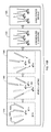
- Time course of Multipatcher operation A representative trace of resistance readings recorded from the four channels of the multipatcher during a full trial is shown in the graph in FIG. 12 .
- the resistance traces are shown for channels 1 ( 1210 ), 2 ( 1220 ), 3 ( 1230 ), and 4 ( 1240 ).
- the key events during the trial are denoted by time dividing lines 1245 , 1250 , 1255 , 1260 , 1265 , 1270 , 1275 , 1280 , 1285 , 1290 , 1295 .
- the detection of a neuron by channel 3 1230 is shown at time 1245 .
- the robot paused again, to successfully attempt a gigaseal formation in channel 1 1210 .
- the same sequence of events was applied to channel 4 1240 , and a successful gigaseal resulted between time 1280 and time 1290 .
- the gigasealed neurons attached to the patch electrodes in channels 1 1210 , 3 1230 , and 4 1240 were broken into to establish whole cell patch recordings.
- the time for execution of gigasealing tasks was fixed at 60 seconds, whereas in the autopatcher, break-in was initiated at the discretion of the experimenters. Thus, average gigasealing time reported for the autopatcher is higher than 60 seconds.
- the gigasealing times recorded for autopatching are the times taken for gigaseals to fully stabilize and asymptote, upon which break-in was initiated by the experimenter.
- a fixed time was employed for gigasealing with the cell being clamped at ⁇ 70 mV holding potential at the end of the 60-second gigasealing process.
- the time taken to fill, install, and position the pipettes in a multipatching trial was measured.
- the increased time for pipette installation per channel is due to the increased complexity of tasks involved in positioning the pipettes in close confinement. However, this is offset somewhat by the reduced time for operation/channel, mainly due to limiting the gigasealing operations of all but one channel to 60 seconds.
- FIG. 13A Representative voltage traces recorded simultaneously from a triplet of neurons in current clamp mode that were simultaneously whole cell recorded using the multipatcher are shown in FIG. 13A .
- the three neurons were targeted in the motor cortex, ⁇ 700 micrometers from each other.
- Mean resting potentials for the neurons were ⁇ 55.93+7.21 mV (top 1310), ⁇ 60.3+4.52 mV (center 1320) and ⁇ 69.23+4.58 mV (bottom 1330 ).
- a majority of the neurons exhibited up and down states, typical of cortical neurons under anesthesia. The up and down states in all neurons were highly correlated, as can be seen in FIG.
- FIG. 13B which is a detail view of sub-threshold membrane potential fluctuations during the time highlighted by dashed box 1340 in FIG. 13A .
- Neurons recorded displayed a high degree of correlation in the up and down state fluctuations. Spikes in this time period have been truncated for better visualization.
- FIGS. 14A-C are current traces showing the results of investigation of synaptic connectivity between whole cell patched neurons using the neurons recorded in FIGS. 13A-B .
- 80 pA of somatic current injection in the neuron shown in the top trace 410 elicited no response in the other two cells 420 , 430 despite spiking.
- 120 pA current in the neuron recording shown in the middle trace 420 and in FIG.
- the whole cell patched neurons were grouped into those that were gigasealed immediately upon detection, and those that were held in gigasealed states for longer periods of time during neuron hunting in other channels. Between these two groups, the access resistances and the resting membrane potentials were compared, being indicators of the quality of the recording obtained. All parameters reported here are in the uncompensated form (i.e. no series resistance or capacitance compensation), obtained using the conventional patch clamp software after autopatcher program completion. Previous literature has suggested that holding neurons for prolonged periods of time in gigaseal cell attached state leads to higher access resistances. Further, it was desired to assess the effect, if any, that tissue displacement had on these gigasealed neurons.
- mice were removed from the stereotax and placed in a custom-built low profile holder.
- a dental drill was used to open up 4 craniotomies (0.25-0.5 mm diameter, within a spacing of 1 mm) by thinning the skull until ⁇ 100 ⁇ m thick, and then a small aperture was opened up with a 30 gauge needle tip.
- Cortical craniotomies were opened at stereotaxic coordinates: anteroposterior, ⁇ 1.5 to +0 mm relative to bregma; mediolateral, 1-3 mm left or right of the midline; neuron hunting typically began at a depth of ⁇ 400 ⁇ m depth.
- the dura was removed using a pair of fine forceps, or in some instances, not removed at all.
- 2% agarose was used to cover the brain surface. Experiments typically lasted 5 hours, at the end of which the mice were euthanized via cervical dislocation when fully anesthetized.
- Borosilicate glass pipettes (Warner) with resistances between 3-9 MW were pulled using a filament micropipette puller (Flaming-Brown P97 model, Sutter Instruments) and stored in a closed petri dish to reduce dust contamination. During each experiment at least 60-70 pipettes were used.
- intracellular pipette solution consisting of (in mM): 125 potassium gluconate (with more added empirically at the end, to bring osmolarity up to ⁇ 290 mOsm), 0.1 CaCl 2 , 0.6 MgCl 2 , 1 EGTA, 10 HEPES, 4 Mg ATP, 0.4 Na GTP, 8 NaCl (pH 7.23, osmolarity 289 mOsm), as used in the past.
- intracellular pipette solution consisting of (in mM): 125 potassium gluconate (with more added empirically at the end, to bring osmolarity up to ⁇ 290 mOsm), 0.1 CaCl 2 , 0.6 MgCl 2 , 1 EGTA, 10 HEPES, 4 Mg ATP, 0.4 Na GTP, 8 NaCl (pH 7.23, osmolarity 289 mOsm), as used in the past.
- the first step of the process started with the pipettes having been installed in the holders.
- a program valve_reset.vi was executed in Labview to configure the pressure switching board to its default configuration, resulting in all pipettes being maintained in high positive pressure state.
- 3-axis linear actuators (Sutter Instruments) were employed to manually position the pipette tips over the craniotomy (or multiple craniotomies) 20-30 mm above the brain surface using a control joystick with the aid of a stereomicroscope (Nikon).
- the pipette voltage offsets were automatically nullified by the “pipette offset” function in the Multiclamp Commander (Molecular Devices) and the Multipatcher_ver1.0.vi program initiated.
- the multipatcher represents the first demonstration of a scalable platform capable of conducting multidimensional single cell measurements at the neuronal circuit level. For the first time, a realistic solution for linking cellular level measurements to systems level characterization in the intact brain has emerged.
- the processes developed for the multipatcher build on the existing autopatcher process that has been previously reported (U.S. patent application Ser. No. 13/676,082, filed Nov. 13, 2012) and take into consideration the mechanical interactions of pipettes and the surrounding brain tissue while being actuated.
- the quality of recordings obtained with the mutlipatcher robot was comparable to the quality of recordings obtained with the single channel autopatcher system. When combined with custom hardware, it is thus scalable to control arbitrarily large numbers of pipettes in the intact brain.
- the hardware can be miniaturized with better precision in placement within much smaller regions spanning local microcircuits ( ⁇ 200 ⁇ m), it can be used to assess synaptic connectivity between neurons in a microcircuit in the intact brain.
- Multiple electrodes can also be used to record from varied interconnected regions of the brain, opening up possible experiments to assess how sub-threshold membrane potential fluctuations are correlated across these regions, such sensory thalamo-cortical circuits, or even more dynamic processes like memory formation.
- the scalability in the electrode numbers means that the multipatcher can be used as a high-throughput tool for systematically obtaining large electrophysiological datasets for analyzing brain circuits. If combined with processes that enable automated single cell RNA harvesting, the robot can be used to probe and obtain genetic information from large numbers of cells.
- Such a strategy can be generalized to other frontiers in biology, bioengineering, and medicine, in which the assessment of the properties of single cells, embedded within intact tissue, is desired but has not previously been achievable in a systematic high-throughput fashion.
- analyzing how different cells in a neural circuit respond to a drug in specific brain states may provide fundamental new capabilities in diagnostics, personalized medicine, and drug development.
- the hardware architecture makes it amenable to integration with optical components for optogenetic stimulation. This combined approach will enable assessments of the synaptic basis of how specific cell types coordinate network activity.
- the multipatcher opens up several interesting engineering challenges for scaling up. Currently, there are some limitations to the number of electrodes that can be simultaneously manipulated using these actuator systems due to their macroscopic scale. Attempting to build very large arrays using conventional apparatus would run into stereotactic hindrance within 6-12 pipettes. Alternate strategies for miniaturizing the actuation systems, as well as using novel electrodes such as flexible fused silica pipettes can be explored.
Landscapes
- Health & Medical Sciences (AREA)
- Life Sciences & Earth Sciences (AREA)
- Surgery (AREA)
- Engineering & Computer Science (AREA)
- Animal Behavior & Ethology (AREA)
- General Health & Medical Sciences (AREA)
- Biomedical Technology (AREA)
- Heart & Thoracic Surgery (AREA)
- Medical Informatics (AREA)
- Molecular Biology (AREA)
- Veterinary Medicine (AREA)
- Public Health (AREA)
- Nuclear Medicine, Radiotherapy & Molecular Imaging (AREA)
- Physics & Mathematics (AREA)
- Biophysics (AREA)
- Pathology (AREA)
- Robotics (AREA)
- Radiology & Medical Imaging (AREA)
- Apparatus Associated With Microorganisms And Enzymes (AREA)
- Neurology (AREA)
Abstract
Description
| TABLE 1 | |||||||||
| 200 |
250 |
300 |
350 |
400 |
450 |
500 ms | 750 |
1000 |
|
| 150 KPa | Attempt | Attempt | Attempt | Attempt | Attempt | Attempt | | Attempt | Attempt | |
| 1 | 2 | 3 | 4 | 5 | 6 | 21 | 22 | 23 | ||
| 200 KPa | Attempt | Attempt | Attempt | Attempt | Attempt | — | Attempt | Attempt | Attempt | |
| 7 | 8 | 9 | 10 | 11 | 24 | 25 | 26 | |||
| 250 KPa | Attempt | Attempt | Attempt | Attempt | Attempt | — | — | — | — | |
| 12 | 13 | 14 | 15 | 16 | ||||||
| 300 KPa | Attempt | Attempt | Attempt | Attempt | — | — | — | — | — | |
| 17 | 18 | 19 | 20 | |||||||
Claims (20)
Priority Applications (1)
| Application Number | Priority Date | Filing Date | Title |
|---|---|---|---|
| US14/079,630 US9498293B2 (en) | 2011-11-11 | 2013-11-13 | Automated cell patch clamping method and apparatus |
Applications Claiming Priority (4)
| Application Number | Priority Date | Filing Date | Title |
|---|---|---|---|
| US201161558841P | 2011-11-11 | 2011-11-11 | |
| US201261726008P | 2012-11-13 | 2012-11-13 | |
| US13/676,082 US9668804B2 (en) | 2011-11-11 | 2012-11-13 | Automated cell patch clamping method and apparatus |
| US14/079,630 US9498293B2 (en) | 2011-11-11 | 2013-11-13 | Automated cell patch clamping method and apparatus |
Related Parent Applications (1)
| Application Number | Title | Priority Date | Filing Date |
|---|---|---|---|
| US13/676,082 Continuation-In-Part US9668804B2 (en) | 2011-11-11 | 2012-11-13 | Automated cell patch clamping method and apparatus |
Publications (2)
| Publication Number | Publication Date |
|---|---|
| US20140228857A1 US20140228857A1 (en) | 2014-08-14 |
| US9498293B2 true US9498293B2 (en) | 2016-11-22 |
Family
ID=51297967
Family Applications (1)
| Application Number | Title | Priority Date | Filing Date |
|---|---|---|---|
| US14/079,630 Expired - Fee Related US9498293B2 (en) | 2011-11-11 | 2013-11-13 | Automated cell patch clamping method and apparatus |
Country Status (1)
| Country | Link |
|---|---|
| US (1) | US9498293B2 (en) |
Cited By (1)
| Publication number | Priority date | Publication date | Assignee | Title |
|---|---|---|---|---|
| US10993634B2 (en) | 2016-07-06 | 2021-05-04 | Massachusetts Institute Of Technology | Image-guided closed-loop robotic system for automated whole-cell patch clamping electrophysiology of neurons in vivo |
Families Citing this family (5)
| Publication number | Priority date | Publication date | Assignee | Title |
|---|---|---|---|---|
| US10830758B2 (en) * | 2015-08-09 | 2020-11-10 | Georgia Tech Research Corporation | Systems and methods enabling patch-clamp re-use |
| US10324080B2 (en) | 2015-11-17 | 2019-06-18 | Purdue Research Foundation | Systems and methods for automated image-guided patch-clamp electrophysiology in vitro |
| EP4413943A3 (en) * | 2016-01-20 | 2024-11-13 | Intuitive Surgical Operations, Inc. | System for rapid halt and recovery of motion deviations in medical device repositionable arms |
| CN107551387B (en) * | 2017-08-17 | 2020-05-15 | 济南优科医疗技术有限公司 | Multifunctional auxiliary treatment robot |
| US20240168041A1 (en) * | 2021-04-14 | 2024-05-23 | Georgia Tech Research Corporation | Systems and methods enabling pharmacology sample testing of patch-clamp samples |
Citations (2)
| Publication number | Priority date | Publication date | Assignee | Title |
|---|---|---|---|---|
| US20120027807A1 (en) * | 2008-10-09 | 2012-02-02 | The General Hospital Corporation | Tissue engineered myocardium and methods of production and uses thereof |
| US20120083861A1 (en) * | 2010-10-04 | 2012-04-05 | The General Hospital Corporation | Selective activation of neurons by sinusoidal electric stimulation |
-
2013
- 2013-11-13 US US14/079,630 patent/US9498293B2/en not_active Expired - Fee Related
Patent Citations (2)
| Publication number | Priority date | Publication date | Assignee | Title |
|---|---|---|---|---|
| US20120027807A1 (en) * | 2008-10-09 | 2012-02-02 | The General Hospital Corporation | Tissue engineered myocardium and methods of production and uses thereof |
| US20120083861A1 (en) * | 2010-10-04 | 2012-04-05 | The General Hospital Corporation | Selective activation of neurons by sinusoidal electric stimulation |
Non-Patent Citations (1)
| Title |
|---|
| Mandi Azizian, Student Member, IEEE, Rajni Patel, Fellow, IEEE, Cezar Gavrilovici and Michael Poulter, Computer-Assisted Patch Clamping, 2010 IEEE International Conference on Robotics and Automation, Anchorage Convention District, May 3-8, 2010, Anchorage, Alaska, USA, pp. 4131-4136. * |
Cited By (1)
| Publication number | Priority date | Publication date | Assignee | Title |
|---|---|---|---|---|
| US10993634B2 (en) | 2016-07-06 | 2021-05-04 | Massachusetts Institute Of Technology | Image-guided closed-loop robotic system for automated whole-cell patch clamping electrophysiology of neurons in vivo |
Also Published As
| Publication number | Publication date |
|---|---|
| US20140228857A1 (en) | 2014-08-14 |
Similar Documents
| Publication | Publication Date | Title |
|---|---|---|
| US9498293B2 (en) | Automated cell patch clamping method and apparatus | |
| Kodandaramaiah et al. | Multi-neuron intracellular recording in vivo via interacting autopatching robots | |
| Tasnim et al. | Emerging bioelectronics for brain organoid electrophysiology | |
| US9668804B2 (en) | Automated cell patch clamping method and apparatus | |
| Kodandaramaiah et al. | Automated whole-cell patch-clamp electrophysiology of neurons in vivo | |
| Peng et al. | High-throughput microcircuit analysis of individual human brains through next-generation multineuron patch-clamp | |
| Salatino et al. | Glial responses to implanted electrodes in the brain | |
| Hong et al. | Novel electrode technologies for neural recordings | |
| Judkewitz et al. | Targeted single-cell electroporation of mammalian neurons in vivo | |
| Hong et al. | Tissue-like neural probes for understanding and modulating the brain | |
| Guitchounts et al. | A carbon-fiber electrode array for long-term neural recording | |
| Kodandaramaiah et al. | Assembly and operation of the autopatcher for automated intracellular neural recording in vivo | |
| KR20070020001A (en) | High Throughput Electrophysiological System | |
| Holst et al. | Autonomous patch-clamp robot for functional characterization of neurons in vivo: development and application to mouse visual cortex | |
| Olt et al. | Physiological recordings from the zebrafish lateral line | |
| Fiáth et al. | Large-scale recording of thalamocortical circuits: in vivo electrophysiology with the two-dimensional electronic depth control silicon probe | |
| Liu et al. | From lithographically patternable to genetically patternable electronic materials for miniaturized, scalable, and soft implantable bioelectronics to interface with nervous and cardiac systems | |
| EP4058402A1 (en) | 3d microelectrode array (mea) for optical and electrical probing of electrogenic cells | |
| US10993634B2 (en) | Image-guided closed-loop robotic system for automated whole-cell patch clamping electrophysiology of neurons in vivo | |
| CN110582569A (en) | Methods and systems for functional maturation of iPSC and ESC-derived cardiomyocytes | |
| Osanai et al. | Hybrid microdrive system with recoverable opto-silicon probe and tetrode for dual-site high density recording in freely moving mice | |
| KR20200080046A (en) | Cell culture structure controlled by magnetic field, cell culture system using thereof and method of connecting neuron using thereof | |
| WO2019112750A9 (en) | Apparatus and methods for fluidic microactuation of electrodes | |
| Kumar et al. | Engineering microscale systems for fully autonomous intracellular neural interfaces | |
| US20120041294A1 (en) | Individually Adjustable Multi-channel Systems in vivo Recording |
Legal Events
| Date | Code | Title | Description |
|---|---|---|---|
| AS | Assignment |
Owner name: NATIONAL SCIENCE FOUNDATION, VIRGINIA Free format text: CONFIRMATORY LICENSE;ASSIGNOR:MASSACHUSETTS INSTITUTE OF TECHNOLOGY;REEL/FRAME:035762/0930 Effective date: 20150515 |
|
| FEPP | Fee payment procedure |
Free format text: PAYOR NUMBER ASSIGNED (ORIGINAL EVENT CODE: ASPN); ENTITY STATUS OF PATENT OWNER: LARGE ENTITY |
|
| ZAAA | Notice of allowance and fees due |
Free format text: ORIGINAL CODE: NOA |
|
| ZAAB | Notice of allowance mailed |
Free format text: ORIGINAL CODE: MN/=. |
|
| STCF | Information on status: patent grant |
Free format text: PATENTED CASE |
|
| AS | Assignment |
Owner name: MASSACHUSETTS INSTITUTE OF TECHNOLOGY, MASSACHUSET Free format text: ASSIGNMENT OF ASSIGNORS INTEREST;ASSIGNORS:KODANDARAMAIAH, SUHASA BANGALORE;BOYDEN, EDWARD STUART;SIGNING DATES FROM 20170501 TO 20170503;REEL/FRAME:042311/0124 Owner name: GEORGIA TECH RESEARCH CORPORATION, GEORGIA Free format text: ASSIGNMENT OF ASSIGNORS INTEREST;ASSIGNOR:FOREST, CRAIG RICHARD;REEL/FRAME:042311/0336 Effective date: 20170502 |
|
| MAFP | Maintenance fee payment |
Free format text: PAYMENT OF MAINTENANCE FEE, 4TH YEAR, LARGE ENTITY (ORIGINAL EVENT CODE: M1551); ENTITY STATUS OF PATENT OWNER: LARGE ENTITY Year of fee payment: 4 |
|
| FEPP | Fee payment procedure |
Free format text: MAINTENANCE FEE REMINDER MAILED (ORIGINAL EVENT CODE: REM.); ENTITY STATUS OF PATENT OWNER: LARGE ENTITY |
|
| LAPS | Lapse for failure to pay maintenance fees |
Free format text: PATENT EXPIRED FOR FAILURE TO PAY MAINTENANCE FEES (ORIGINAL EVENT CODE: EXP.); ENTITY STATUS OF PATENT OWNER: LARGE ENTITY |
|
| STCH | Information on status: patent discontinuation |
Free format text: PATENT EXPIRED DUE TO NONPAYMENT OF MAINTENANCE FEES UNDER 37 CFR 1.362 |
|
| FP | Lapsed due to failure to pay maintenance fee |
Effective date: 20241122 |