US9497386B1 - Multi-imager video camera with automatic exposure control - Google Patents
Multi-imager video camera with automatic exposure control Download PDFInfo
- Publication number
- US9497386B1 US9497386B1 US12/887,279 US88727910A US9497386B1 US 9497386 B1 US9497386 B1 US 9497386B1 US 88727910 A US88727910 A US 88727910A US 9497386 B1 US9497386 B1 US 9497386B1
- Authority
- US
- United States
- Prior art keywords
- imager
- imagers
- auto
- auto exposure
- array
- Prior art date
- Legal status (The legal status is an assumption and is not a legal conclusion. Google has not performed a legal analysis and makes no representation as to the accuracy of the status listed.)
- Active, expires
Links
Images


Classifications
-
- H—ELECTRICITY
- H04—ELECTRIC COMMUNICATION TECHNIQUE
- H04N—PICTORIAL COMMUNICATION, e.g. TELEVISION
- H04N7/00—Television systems
- H04N7/18—Closed-circuit television [CCTV] systems, i.e. systems in which the video signal is not broadcast
- H04N7/181—Closed-circuit television [CCTV] systems, i.e. systems in which the video signal is not broadcast for receiving images from a plurality of remote sources
-
- H04N5/2351—
-
- H—ELECTRICITY
- H04—ELECTRIC COMMUNICATION TECHNIQUE
- H04N—PICTORIAL COMMUNICATION, e.g. TELEVISION
- H04N23/00—Cameras or camera modules comprising electronic image sensors; Control thereof
- H04N23/70—Circuitry for compensating brightness variation in the scene
- H04N23/71—Circuitry for evaluating the brightness variation
-
- H—ELECTRICITY
- H04—ELECTRIC COMMUNICATION TECHNIQUE
- H04N—PICTORIAL COMMUNICATION, e.g. TELEVISION
- H04N23/00—Cameras or camera modules comprising electronic image sensors; Control thereof
- H04N23/60—Control of cameras or camera modules
- H04N23/698—Control of cameras or camera modules for achieving an enlarged field of view, e.g. panoramic image capture
-
- H—ELECTRICITY
- H04—ELECTRIC COMMUNICATION TECHNIQUE
- H04N—PICTORIAL COMMUNICATION, e.g. TELEVISION
- H04N23/00—Cameras or camera modules comprising electronic image sensors; Control thereof
- H04N23/80—Camera processing pipelines; Components thereof
-
- H—ELECTRICITY
- H04—ELECTRIC COMMUNICATION TECHNIQUE
- H04N—PICTORIAL COMMUNICATION, e.g. TELEVISION
- H04N5/00—Details of television systems
- H04N5/222—Studio circuitry; Studio devices; Studio equipment
- H04N5/262—Studio circuits, e.g. for mixing, switching-over, change of character of image, other special effects ; Cameras specially adapted for the electronic generation of special effects
- H04N5/2628—Alteration of picture size, shape, position or orientation, e.g. zooming, rotation, rolling, perspective, translation
-
- H—ELECTRICITY
- H04—ELECTRIC COMMUNICATION TECHNIQUE
- H04N—PICTORIAL COMMUNICATION, e.g. TELEVISION
- H04N5/00—Details of television systems
- H04N5/222—Studio circuitry; Studio devices; Studio equipment
- H04N5/262—Studio circuits, e.g. for mixing, switching-over, change of character of image, other special effects ; Cameras specially adapted for the electronic generation of special effects
- H04N5/265—Mixing
-
- H—ELECTRICITY
- H04—ELECTRIC COMMUNICATION TECHNIQUE
- H04N—PICTORIAL COMMUNICATION, e.g. TELEVISION
- H04N7/00—Television systems
- H04N7/18—Closed-circuit television [CCTV] systems, i.e. systems in which the video signal is not broadcast
Definitions
- the present invention relates to generally to video camera systems.
- Video camera systems are commonly used for video surveillance of prescribed areas. For example, such systems are used for surveillance of parking lots, department stores, casinos, banks, and other areas of interest.
- Conventional video cameras commonly used in such systems include fixed-type and movable-type cameras.
- the fixed-type cameras may be configured to observe a fixed area
- the movable-type cameras may be configured with pan-and-tilt motor units to observe a wide area range.
- One embodiment relates to a multi-imager video camera that includes a plurality of imagers, a plurality of image flow processors, a multi-imager video processor, a plurality of exposure control circuits, and a statistics circuit.
- Each imager includes a sensor array that is configured to capture image frames, and each image flow processor is configured to receive and process the image frames captured from at least one of said imagers.
- the multi-imager video processor is configured to receive the processed image frames from the plurality of image flow processors.
- the statistics circuit is configured to determine an auto exposure level based on the captured image frames from a single imager.
- the multi-image video processor is further configured to receive said auto exposure level and transmit said auto exposure level to all other imagers of the plurality of imagers.
- Another embodiment relates to a method of automatic exposure control for a multi-imager video camera.
- Each imager of an array of imagers in the camera captures image frames and transmits the captured image frames to an associated image flow processor.
- Each image flow processor processes the captured image frames and transmits the processed image frames to a multi-imager video processor.
- a statistics circuit receives the captured image frames from a single imager and thereby determines an auto exposure level for the single imager.
- the multi-imager video processor receives the auto exposure level for the single imager and transmits the auto exposure level for the single imager to all other imagers in the array. Exposure control circuits for all the imagers of the array apply the auto exposure level.
- Another embodiment relates to a multi-imager camera which includes an array of imagers, each imager being configured to capture image frames.
- the camera includes means for determining an auto exposure level based on the captured image frames from a single imager, means for transmitting the auto exposure level for the single imager to all other imagers in the array, and means for applying the auto exposure level in all imagers in the array.
- FIG. 1A shows a top schematic view showing select components of a video camera in accordance with an embodiment of the invention.
- FIG. 1B shows a front perspective view of a video camera in accordance with an embodiment of the invention.
- FIG. 2A is a schematic diagram of an imager board of the video camera in accordance with one embodiment of the invention.
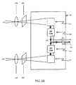
- FIG. 2B is a schematic diagram of an imager board of the video camera in accordance with another embodiment of the invention.
- FIG. 3 is a schematic diagram depicting selection of primary image frames from source image frames for multiple sensors of a video camera in accordance with another embodiment of the invention.
- FIG. 4 is an example final image frame resulting from the primary image frames for the multiple sensors of the video camera in accordance with another embodiment of the invention.
- FIG. 5 is a schematic diagram showing pixel processing components of an image flow processor in accordance with another embodiment of the invention.
- FIG. 6 is a diagram showing two sets of color temperature ranges for the application of anti-rolloff configuration parameters in accordance with another embodiment of the invention.
- FIG. 7 is a schematic diagram illustrating a technique for auto-exposure-control and auto-white-balance for multiple sensors of a video camera in accordance with another embodiment of the invention.
- FIG. 8 is a schematic diagram illustrating a technique for enabling frame-by-frame view switching in accordance with another embodiment of the invention.
- FIG. 9 illustrates re-sizing of an image frame in accordance with an embodiment of the invention.
- FIG. 10A illustrates horizontal cropping of an image frame in accordance with an embodiment of the invention.
- FIG. 10B illustrates vertical cropping which may be applied after horizontal cropping in accordance with an embodiment of the invention.
- FIG. 11 is a schematic diagram illustrating the video camera disclosed herein as interconnected to a plurality of user computers via a network in accordance with an embodiment of the invention.
- FIG. 1A shows a top schematic view showing select components of a video camera in accordance with an embodiment of the invention.
- the video camera includes a camera body 102 , a main board 104 , a multi-imager video processor 106 , and five imager boards 108 .
- the camera has a diameter D, and each imager board is of a width W.
- Shown in FIG. 1A are a field of view 110 for a single imager and a field of view 116 from two adjacent imagers.
- a select-angle field of view 112 may be selected.
- the single-imager field of view 110 is 38 degrees wide, and the select-angle field of view 112 is 36 degrees wide.
- a small vertical slice 114 (approximately an inch wide, for example) which is between select-angle fields of view 112 of adjacent imagers. As seen in FIG. 1A , his small vertical slice 114 is defined by approximately parallel lines such that the width of the vertical slice 114 is approximately constant and independent of the distance away from the camera. These vertical slices between adjacent imagers are not captured within the final image generated by combining the select-angle fields of view 112 from the five imagers.
- FIG. 1B shows a front perspective view of a video camera in accordance with an embodiment of the invention.
- the front of the camera may include five faces 120 (- 0 through - 4 ) corresponding to the five imager boards 108 .
- each imager board 108 includes two sensors 122 and 124 .
- one sensor 122 may be configured to capture daylight images, while the other sensor 124 may be configured to capture nightlight (low light) images.
- one sensor 122 may be configured to capture lower resolution images, while the other sensor 124 may be configured to capture higher resolution images.
- FIG. 2A is a schematic diagram of an imager board 210 of the video camera in accordance with one embodiment of the invention.
- the image light 201 that is received by a first imager (image sensor) 212 is focused by a first barrel lens 202 and filtered by a first infra-red cut filter 204
- the image light 205 that is received by a second imager (image sensor) 214 is focused by a first barrel lens 206 and filtered by a first infra-red cut filter 208
- the first barrel lens 202 may be 12 mm or less in length and have an F# greater than 2.2
- the second barrel lens 206 may be 12 mm or less in length and have an F# less than 2.2.
- the first infra-red cut filter 204 may cutoff (block) infrared light in the wavelength range of 600 nm to 700 nm.
- the second infra-red cut filter 206 may cutoff (block) infrared light with wavelengths greater than 700 nm, or, alternatively, the second infra-red cut filter 206 may be absent.
- the first imager 212 may be configured as a “day” imager that is optimized for good color fidelity and sharpness
- the second imager 214 may be configured as a “night” imager that is optimized for good low-light performance.
- the first imager may be implemented, for example, as a CMOS image sensor array with more than 1.2 million pixels and a pixel size less than 4 microns in width.
- the image output by the first imager 212 may have a signal-to-noise ratio of greater than 10 dB when scene lighting is greater than 200 Lux.
- the second imager may be implemented, for example, as a CMOS image sensor array with less than 1.2 million pixels and a pixel size greater than 3 microns in width.
- the image output by the second imager 214 may have a signal-to-noise ratio of greater than 10 dB when scene lighting is less than 2 Lux.
- the first and second imagers 212 and 214 may be controlled by way of control signals received via a control bus 215 .
- the control bus 215 may be implemented as an I2C bus, for example.
- a first serial bus 216 may be used to communicate the output image data from the first imager 212 to a day/night multiplexer 220 on the image flow processor (IFP) 211
- a second serial bus 218 may be used to communicate the output image data from the second imager 214 to the day/night multiplexer 220 on the IFP 211
- the first and second serial buses may be implemented as MIPI buses.
- the multiplexer 220 selects the image data from either the first serial bus 216 (i.e. from the first imager) or the second serial bus 218 (i.e. from the second imager).
- the selected image data is then received by the IFP core 222 .
- the IFP core 222 may output image data via a serial bus (for example, an MIPI bus) 224 to a multi-imager video processor (MIVP).
- a connector 215 may be used to connect the control bus 215 and the serial bus 224 to the MIVP.
- FIG. 2B is a schematic diagram of an imager board 250 of the video camera in accordance with another embodiment of the invention.
- the imager board 250 of FIG. 2B differs from the imager board 210 of FIG. 2A in a few ways.
- IFP core 222 instead of one IFP core 222 , there are two IFP cores 252 and 254 which each receives data from one of the two imagers 212 and 214 .
- IFP cores 252 and 254 may be integrated with the integrated circuits (ICs) of their respective imagers 212 and 214 , or they may be implemented as separate ICs.
- ICs integrated circuits
- a shared parallel bus 256 is used to select and output the image data the the MIVP.
- control signals from the control bus 258 ensures that only one IFP core is driving the parallel bus 256 at any one time (to avoid contention).
- the connector 260 may be used to connect the control bus 258 and the parallel bus 256 to the MIVP.
- FIG. 3 is a schematic diagram depicting selection of primary image frames from source image frames for multiple sensors of a video camera in accordance with another embodiment of the invention.
- the five source rectangles (CTG0 SOURCE-RECT, CTG1 SOURCE-RECT, CTG2 SOURCE-RECT, CTG3 SOURCE-RECT, CTG4 SOURCE-RECT and CTG5 SOURCE-RECT) are the source image data within the field of view of the five imagers of the video camera.
- the source rectangles (for example, each 1536 ⁇ 2048 pixels) are depicted as non-aligned because the imagers are expected to have mechanical imperfections.
- the five primary rectangles are selected by each IFP core “cherry picking” a smaller rectangle (for example, 1300 ⁇ 1800 pixels) within its field of view.
- a smaller rectangle for example, 1300 ⁇ 1800 pixels
- the source rectangles may obtain image data from a 38 degree wide field of view
- the primary rectangles may represent the image data from a slightly narrower 36 degree field of view.
- FIG. 4 is an example final image frame resulting from the multiple sensors of the video camera in accordance with another embodiment of the invention.
- the final image frame may be 1920 ⁇ 1080 pixels, as shown in FIG. 4 . Note that no digital stitching is required to obtain this final image.
- FIG. 5 is a schematic diagram showing pixel processing components of an image flow processor (IFP) in accordance with another embodiment of the invention.
- the image sensor array imager
- the IFP core includes, among other components, an anti-roll-off block, a color recovery block, a color correction block, and a gamma correction block. These blocks process the pixel data.
- the processed pixel data is then transmitted to the multi-imager video processor.
- FIG. 6 is a diagram showing two sets of color (black-body) temperature ranges for the application of anti-rolloff configuration parameters in accordance with another embodiment of the invention.
- Each set includes four color temperature ranges for the application of different anti-rolloff configuration parameters.
- the four color temperature ranges in each set are labeled 2900K, 4000K, 5000K, and 6500K.
- the first set of color temperature ranges 502 are shifted in temperature compared with the second set of color temperature ranges 504 .
- a transition to a higher range occurs according to the first set of ranges 502
- a transition to a lower range occurs according to the second set of ranges.
- FIG. 7 is a schematic diagram illustrating a technique for auto-exposure-control (AEC) and auto-white-balance (AWB) for multiple sensors of a video camera in accordance with another embodiment of the invention.
- AEC auto-exposure-control
- AMB auto-white-balance
- the AEC and AWB for each sensor is controlled by a control blocks for the sensor and associated IFP and uses a statistics block to analyze data from the associated IFP.
- the video camera is configured such that the AEC and AWB is turned on at the microcontroller ( ⁇ controller) for only one of the five imagers, and turned off at the microcontroller for the other four imagers.
- the AEC and AWB is turned on only at the microcontroller for the middle imager of the array of imagers (for example, the imager being used, either day 122 or night 124 , of face 120 - 2 in FIG. 1B ).
- the AEC and AWB updates from the single AEC/AWB-enabled imager may be transmitted 702 to the MIVP.
- the MIVP may then clone (copy) the AEC and AWB updates and send 704 them to the other imagers.
- This configuration is very low cost and efficient to implement and advantageously provides AEC and AWB across all the five imagers in a synchronized manner.
- FIG. 8 is a schematic diagram illustrating a technique for enabling frame-by-frame view switching in accordance with another embodiment of the invention. Shown in this figure is one imager of the multiple imagers in the camera.
- the sensor array of each imager performs cropping from the source rectangular frame (CTG SOURCE-RECT) to the primary rectangular frame (CTG PRIMARY-RECT).
- circuitry may be included in the sensor IC for integration time control and analog gain control.
- the integration time control is used to provide exposure control, while the analog gain control is used to provide white balance control.
- the IFP for each imager may include resizing and cropping circuitry.
- the IFP may be incorporated onto the same integrated circuit as the sensor array, or the IFP may be implemented on a separate integrated circuit.
- the IFP first resizes the image in the primary rectangular frame, and then performs a “horizontal” cropping of the resized image.
- the horizontal cropping may be performed in the sensor by appropriate adjustment of the primary rectangular frame so as to implement the desired horizontal crop.
- An example of a resizing of an image is shown in FIG. 9 .
- the horizontal cropping reduces a number of pixels in a vertical dimension of the image.
- An example of a horizontal cropping of an image is shown in FIG. 10A .
- the MIVP receives the horizontally-cropped resized images from the multiple imagers to obtain a combined image.
- the MIVP may then perform a “vertical” cropping of the combined image to create a final image frame.
- the vertical cropping reduces a number of pixels in a horizontal dimension of the image.
- An example of a vertical cropping of an image is shown in FIG. 10B .
- the technique of performing the horizontal cropping in the IFP (or sensor circuitry) and vertical cropping in the MIVP is advantageously efficient and reduces the amount of image data that is needed to be received and processed by the MIVP.
- each update queue may be configured to hold parameters to be sent on a frame-by-frame basis to the corresponding imager.
- the parameters may include, for example, the resizing and horizontal cropping parameters for a frame.
- the parameters may also include integration time control and analog gain control parameters to be applied by certain sensors as described above in relation to FIG. 7 .
- a falling edge of a Frame_Valid signal from an imager may cause an interrupt signal to be sent to a microcontroller within the MIVP. The microcontroller may then cause the parameters at the top of the corresponding queue to be released to be applied to the next frame by that imager.
- FIG. 11 is a schematic diagram illustrating the video camera disclosed herein as interconnected to a plurality of user computers 1106 via a network 1104 in accordance with an embodiment of the invention.
- the video camera includes a network processor (packetizer) 1102 .
- packetizer packetizer
- FIG. 11 has a network processor 1102 as a separate processor that is interconnected with the MIVP, another embodiment may have the network processor 1102 as part of the MIVP.
- the MIVP may be configured to encrypt and compress the final image frames to generate encoded image frames.
- the network processor 1102 may be configured to receive the encoded image frames generated by the MIVP and to generate data packets therefrom which are addressed to a plurality of user computers.
- the data packets addressed to a particular user computer contain the encoded image frames which are customized for that user computer.
- each user computer may select a different view for display by way of a user interface on the user computer.
- the user interface may allow the user to crop and re-size the image to be viewed.
- the camera obtains image data at 60 frames per second, and that the priorities between the users is such that User A is to receive video at 30 frames per second, User B is to receive video at 10 frames per second, and User C is to receive video at 20 frames per second.
- A indicates parameters for the view requested by User A
- B indicates parameters for the view requested by User B
- C indicates parameters for the view requested by User C).
- the network processor may packetize those frames with the network address of User A and transmit those packets to User A via the network.
- the network processor may packetize those frames with the network address of User B and transmit those packets to User B via the network.
- the network processor may packetize those frames with the network address of User C and transmit those packets to User C via the network.
Landscapes
- Engineering & Computer Science (AREA)
- Multimedia (AREA)
- Signal Processing (AREA)
- Studio Devices (AREA)
Abstract
Description
CACBCACACBCACACBCACACBCA . . .
For frames taken with parameters A, the network processor may packetize those frames with the network address of User A and transmit those packets to User A via the network. For frames taken with parameters B, the network processor may packetize those frames with the network address of User B and transmit those packets to User B via the network. For frames taken with parameters C, the network processor may packetize those frames with the network address of User C and transmit those packets to User C via the network.
Claims (11)
Priority Applications (1)
| Application Number | Priority Date | Filing Date | Title |
|---|---|---|---|
| US12/887,279 US9497386B1 (en) | 2009-09-22 | 2010-09-21 | Multi-imager video camera with automatic exposure control |
Applications Claiming Priority (2)
| Application Number | Priority Date | Filing Date | Title |
|---|---|---|---|
| US24486909P | 2009-09-22 | 2009-09-22 | |
| US12/887,279 US9497386B1 (en) | 2009-09-22 | 2010-09-21 | Multi-imager video camera with automatic exposure control |
Publications (1)
| Publication Number | Publication Date |
|---|---|
| US9497386B1 true US9497386B1 (en) | 2016-11-15 |
Family
ID=50896822
Family Applications (3)
| Application Number | Title | Priority Date | Filing Date |
|---|---|---|---|
| US12/887,279 Active 2031-10-28 US9497386B1 (en) | 2009-09-22 | 2010-09-21 | Multi-imager video camera with automatic exposure control |
| US12/887,263 Active 2031-05-25 US8754941B1 (en) | 2009-09-22 | 2010-09-21 | Multi-imager video camera with frame-by-frame view switching |
| US14/271,313 Active US9635273B2 (en) | 2009-09-22 | 2014-05-06 | Multi-imager video camera with frame-by-frame view switching |
Family Applications After (2)
| Application Number | Title | Priority Date | Filing Date |
|---|---|---|---|
| US12/887,263 Active 2031-05-25 US8754941B1 (en) | 2009-09-22 | 2010-09-21 | Multi-imager video camera with frame-by-frame view switching |
| US14/271,313 Active US9635273B2 (en) | 2009-09-22 | 2014-05-06 | Multi-imager video camera with frame-by-frame view switching |
Country Status (1)
| Country | Link |
|---|---|
| US (3) | US9497386B1 (en) |
Cited By (2)
| Publication number | Priority date | Publication date | Assignee | Title |
|---|---|---|---|---|
| CN108010106A (en) * | 2017-11-22 | 2018-05-08 | 努比亚技术有限公司 | A kind of method for displaying image, terminal and computer-readable recording medium |
| US11206358B1 (en) * | 2012-11-29 | 2021-12-21 | Altia Systems Inc | Autoexposure control for multi-imager system synchronized to a single imager |
Families Citing this family (60)
| Publication number | Priority date | Publication date | Assignee | Title |
|---|---|---|---|---|
| US8866920B2 (en) | 2008-05-20 | 2014-10-21 | Pelican Imaging Corporation | Capturing and processing of images using monolithic camera array with heterogeneous imagers |
| US11792538B2 (en) | 2008-05-20 | 2023-10-17 | Adeia Imaging Llc | Capturing and processing of images including occlusions focused on an image sensor by a lens stack array |
| CN103501416B (en) | 2008-05-20 | 2017-04-12 | 派力肯成像公司 | Imaging system |
| EP2502115A4 (en) | 2009-11-20 | 2013-11-06 | Pelican Imaging Corp | CAPTURE AND IMAGE PROCESSING USING A MONOLITHIC CAMERAS NETWORK EQUIPPED WITH HETEROGENEOUS IMAGERS |
| KR101824672B1 (en) | 2010-05-12 | 2018-02-05 | 포토네이션 케이맨 리미티드 | Architectures for imager arrays and array cameras |
| US8878950B2 (en) | 2010-12-14 | 2014-11-04 | Pelican Imaging Corporation | Systems and methods for synthesizing high resolution images using super-resolution processes |
| EP2708019B1 (en) * | 2011-05-11 | 2019-10-16 | FotoNation Limited | Systems and methods for transmitting and receiving array camera image data |
| WO2013043751A1 (en) | 2011-09-19 | 2013-03-28 | Pelican Imaging Corporation | Systems and methods for controlling aliasing in images captured by an array camera for use in super resolution processing using pixel apertures |
| WO2013049699A1 (en) | 2011-09-28 | 2013-04-04 | Pelican Imaging Corporation | Systems and methods for encoding and decoding light field image files |
| EP2817955B1 (en) | 2012-02-21 | 2018-04-11 | FotoNation Cayman Limited | Systems and methods for the manipulation of captured light field image data |
| KR20150023907A (en) | 2012-06-28 | 2015-03-05 | 펠리칸 이매징 코포레이션 | Systems and methods for detecting defective camera arrays, optic arrays, and sensors |
| US20140002674A1 (en) | 2012-06-30 | 2014-01-02 | Pelican Imaging Corporation | Systems and Methods for Manufacturing Camera Modules Using Active Alignment of Lens Stack Arrays and Sensors |
| EP3869797B1 (en) | 2012-08-21 | 2023-07-19 | Adeia Imaging LLC | Method for depth detection in images captured using array cameras |
| EP2888698A4 (en) | 2012-08-23 | 2016-06-29 | Pelican Imaging Corp | HIGH RESOLUTION MOTION ESTIMATING BASED ON ELEMENTS FROM LOW RESOLUTION IMAGES CAPTURED WITH MATRIX SOURCE |
| WO2014078443A1 (en) | 2012-11-13 | 2014-05-22 | Pelican Imaging Corporation | Systems and methods for array camera focal plane control |
| US9462164B2 (en) | 2013-02-21 | 2016-10-04 | Pelican Imaging Corporation | Systems and methods for generating compressed light field representation data using captured light fields, array geometry, and parallax information |
| WO2014138695A1 (en) | 2013-03-08 | 2014-09-12 | Pelican Imaging Corporation | Systems and methods for measuring scene information while capturing images using array cameras |
| US8866912B2 (en) | 2013-03-10 | 2014-10-21 | Pelican Imaging Corporation | System and methods for calibration of an array camera using a single captured image |
| WO2014164909A1 (en) | 2013-03-13 | 2014-10-09 | Pelican Imaging Corporation | Array camera architecture implementing quantum film sensors |
| US9124831B2 (en) | 2013-03-13 | 2015-09-01 | Pelican Imaging Corporation | System and methods for calibration of an array camera |
| US9100586B2 (en) | 2013-03-14 | 2015-08-04 | Pelican Imaging Corporation | Systems and methods for photometric normalization in array cameras |
| US9578259B2 (en) | 2013-03-14 | 2017-02-21 | Fotonation Cayman Limited | Systems and methods for reducing motion blur in images or video in ultra low light with array cameras |
| US10122993B2 (en) | 2013-03-15 | 2018-11-06 | Fotonation Limited | Autofocus system for a conventional camera that uses depth information from an array camera |
| US9438888B2 (en) | 2013-03-15 | 2016-09-06 | Pelican Imaging Corporation | Systems and methods for stereo imaging with camera arrays |
| US9497429B2 (en) | 2013-03-15 | 2016-11-15 | Pelican Imaging Corporation | Extended color processing on pelican array cameras |
| US9445003B1 (en) | 2013-03-15 | 2016-09-13 | Pelican Imaging Corporation | Systems and methods for synthesizing high resolution images using image deconvolution based on motion and depth information |
| US9898856B2 (en) | 2013-09-27 | 2018-02-20 | Fotonation Cayman Limited | Systems and methods for depth-assisted perspective distortion correction |
| WO2015074078A1 (en) | 2013-11-18 | 2015-05-21 | Pelican Imaging Corporation | Estimating depth from projected texture using camera arrays |
| US9426361B2 (en) | 2013-11-26 | 2016-08-23 | Pelican Imaging Corporation | Array camera configurations incorporating multiple constituent array cameras |
| US10089740B2 (en) | 2014-03-07 | 2018-10-02 | Fotonation Limited | System and methods for depth regularization and semiautomatic interactive matting using RGB-D images |
| CN113256730B (en) | 2014-09-29 | 2023-09-05 | 快图有限公司 | Systems and methods for dynamic calibration of array cameras |
| US9741117B2 (en) | 2014-12-22 | 2017-08-22 | Motorola Mobility Llc | Multiple camera apparatus and method for synchronized auto white balance |
| ES2928663T3 (en) | 2015-02-27 | 2022-11-21 | Leia Inc | multi view camera |
| CN204993576U (en) * | 2015-07-21 | 2016-01-20 | 杭州海康威视数字技术股份有限公司 | Camera and integrated circuit board |
| US10623662B2 (en) * | 2016-07-01 | 2020-04-14 | Snap Inc. | Processing and formatting video for interactive presentation |
| US10622023B2 (en) | 2016-07-01 | 2020-04-14 | Snap Inc. | Processing and formatting video for interactive presentation |
| CN110089117B (en) * | 2016-07-01 | 2023-02-17 | 斯纳普公司 | Processing and formatting video for interactive presentation |
| US10419681B2 (en) | 2016-10-26 | 2019-09-17 | Robert Bosch Gmbh | Variable field of view multi-imager |
| CN106534700B (en) * | 2016-12-20 | 2019-07-02 | 济南中维世纪科技有限公司 | A Method of Realizing Soft Photosensitivity Based on Automatic Exposure and Automatic White Balance Algorithm |
| US10475483B2 (en) | 2017-05-16 | 2019-11-12 | Snap Inc. | Method and system for recording and playing video using orientation of device |
| US10482618B2 (en) | 2017-08-21 | 2019-11-19 | Fotonation Limited | Systems and methods for hybrid depth regularization |
| CA3075164C (en) | 2017-10-02 | 2023-06-27 | Leia Inc. | Multiview camera array, multiview system, and method having camera sub-arrays with a shared camera |
| DE112020004391B4 (en) | 2019-09-17 | 2024-08-14 | Intrinsic Innovation Llc | Systems and methods for surface modeling using polarization features |
| EP4038880A1 (en) * | 2019-09-30 | 2022-08-10 | InterDigital VC Holdings France, SAS | A method and apparatus for encoding, transmitting and decoding volumetric video |
| CA3157194C (en) | 2019-10-07 | 2023-08-29 | Boston Polarimetrics, Inc. | Systems and methods for augmentation of sensor systems and imaging systems with polarization |
| US11222401B2 (en) * | 2019-11-14 | 2022-01-11 | Hand Held Products, Inc. | Apparatuses and computer-implemented methods for middle frame image processing |
| CN114787648B (en) | 2019-11-30 | 2023-11-10 | 波士顿偏振测定公司 | Systems and methods for transparent object segmentation using polarization cues |
| JP7462769B2 (en) | 2020-01-29 | 2024-04-05 | イントリンジック イノベーション エルエルシー | System and method for characterizing an object pose detection and measurement system - Patents.com |
| WO2021154459A1 (en) | 2020-01-30 | 2021-08-05 | Boston Polarimetrics, Inc. | Systems and methods for synthesizing data for training statistical models on different imaging modalities including polarized images |
| US11953700B2 (en) | 2020-05-27 | 2024-04-09 | Intrinsic Innovation Llc | Multi-aperture polarization optical systems using beam splitters |
| US12069227B2 (en) | 2021-03-10 | 2024-08-20 | Intrinsic Innovation Llc | Multi-modal and multi-spectral stereo camera arrays |
| US12020455B2 (en) | 2021-03-10 | 2024-06-25 | Intrinsic Innovation Llc | Systems and methods for high dynamic range image reconstruction |
| US11290658B1 (en) | 2021-04-15 | 2022-03-29 | Boston Polarimetrics, Inc. | Systems and methods for camera exposure control |
| US11954886B2 (en) | 2021-04-15 | 2024-04-09 | Intrinsic Innovation Llc | Systems and methods for six-degree of freedom pose estimation of deformable objects |
| US12067746B2 (en) | 2021-05-07 | 2024-08-20 | Intrinsic Innovation Llc | Systems and methods for using computer vision to pick up small objects |
| US12175741B2 (en) | 2021-06-22 | 2024-12-24 | Intrinsic Innovation Llc | Systems and methods for a vision guided end effector |
| US12340538B2 (en) | 2021-06-25 | 2025-06-24 | Intrinsic Innovation Llc | Systems and methods for generating and using visual datasets for training computer vision models |
| US12172310B2 (en) | 2021-06-29 | 2024-12-24 | Intrinsic Innovation Llc | Systems and methods for picking objects using 3-D geometry and segmentation |
| US11689813B2 (en) | 2021-07-01 | 2023-06-27 | Intrinsic Innovation Llc | Systems and methods for high dynamic range imaging using crossed polarizers |
| US12293535B2 (en) | 2021-08-03 | 2025-05-06 | Intrinsic Innovation Llc | Systems and methods for training pose estimators in computer vision |
Citations (15)
| Publication number | Priority date | Publication date | Assignee | Title |
|---|---|---|---|---|
| US5715490A (en) | 1996-01-17 | 1998-02-03 | Minolta Co., Ltd. | Finder field-of-view frame switching mechanism |
| US20030095183A1 (en) | 1999-12-18 | 2003-05-22 | Patricia Roberts | Security camera systems |
| US20030202099A1 (en) | 2002-04-25 | 2003-10-30 | Taku Nakamura | Security camera system |
| US20030206739A1 (en) | 2000-07-04 | 2003-11-06 | Kun-Shan Lu | Audio/video IP camera |
| US20040130655A1 (en) | 2003-01-06 | 2004-07-08 | Kooigi Yanakawa | Network camera |
| US20050012818A1 (en) | 2003-07-17 | 2005-01-20 | Igt | Security camera interface |
| US20050044258A1 (en) | 2003-06-30 | 2005-02-24 | Minoru Nakamura | Network camera |
| US20070098397A1 (en) | 2005-11-01 | 2007-05-03 | D-Link Systems, Inc. | Network camera |
| US20070156854A1 (en) | 2006-01-03 | 2007-07-05 | Avermedia Technologies, Inc. | A system for grabbing images from an ip camera |
| US20080012952A1 (en) * | 2006-07-14 | 2008-01-17 | Lg Electronics Inc. | Mobile terminal and image processing method |
| US20080056708A1 (en) | 2006-08-29 | 2008-03-06 | Nuvico, Inc. | Security camera |
| US20080106634A1 (en) * | 2006-11-07 | 2008-05-08 | Fujifilm Corporation | Multiple lens imaging apparatuses, and methods and programs for setting exposure of multiple lens imaging apparatuses |
| US7520685B2 (en) | 2005-08-19 | 2009-04-21 | Samsung Electronics Co., Ltd. | Security camera |
| EP2066114A1 (en) | 2007-11-29 | 2009-06-03 | Axis AB | Network camera |
| US7936374B2 (en) * | 2002-06-21 | 2011-05-03 | Microsoft Corporation | System and method for camera calibration and images stitching |
Family Cites Families (8)
| Publication number | Priority date | Publication date | Assignee | Title |
|---|---|---|---|---|
| US6930709B1 (en) * | 1997-12-04 | 2005-08-16 | Pentax Of America, Inc. | Integrated internet/intranet camera |
| US7023913B1 (en) * | 2000-06-14 | 2006-04-04 | Monroe David A | Digital security multimedia sensor |
| JP2004062103A (en) * | 2002-07-31 | 2004-02-26 | Sony Corp | Image processing apparatus and method, information processing apparatus and method, recording medium, and program |
| US7548258B2 (en) * | 2003-11-21 | 2009-06-16 | Arecont Vision Llc. | High resolution network video camera with massively parallel implementation of image processing, compression and network server |
| US7945938B2 (en) * | 2005-05-11 | 2011-05-17 | Canon Kabushiki Kaisha | Network camera system and control method therefore |
| JP2007043225A (en) * | 2005-07-29 | 2007-02-15 | Univ Of Electro-Communications | Captured image processing apparatus and captured image processing method |
| JP5355422B2 (en) * | 2007-02-01 | 2013-11-27 | イッサム・リサーチ・デヴェロップメント・カンパニー・オヴ・ザ・ヘブルー・ユニヴァーシティ・オヴ・イェルサレム | Method and system for video indexing and video synopsis |
| TW200907557A (en) * | 2007-08-08 | 2009-02-16 | Behavior Tech Computer Corp | Camera array apparatus and the method for capturing wide-angle video over a network |
-
2010
- 2010-09-21 US US12/887,279 patent/US9497386B1/en active Active
- 2010-09-21 US US12/887,263 patent/US8754941B1/en active Active
-
2014
- 2014-05-06 US US14/271,313 patent/US9635273B2/en active Active
Patent Citations (16)
| Publication number | Priority date | Publication date | Assignee | Title |
|---|---|---|---|---|
| US5715490A (en) | 1996-01-17 | 1998-02-03 | Minolta Co., Ltd. | Finder field-of-view frame switching mechanism |
| US20030095183A1 (en) | 1999-12-18 | 2003-05-22 | Patricia Roberts | Security camera systems |
| US20030206739A1 (en) | 2000-07-04 | 2003-11-06 | Kun-Shan Lu | Audio/video IP camera |
| US20030202099A1 (en) | 2002-04-25 | 2003-10-30 | Taku Nakamura | Security camera system |
| US7936374B2 (en) * | 2002-06-21 | 2011-05-03 | Microsoft Corporation | System and method for camera calibration and images stitching |
| US20040130655A1 (en) | 2003-01-06 | 2004-07-08 | Kooigi Yanakawa | Network camera |
| US20050044258A1 (en) | 2003-06-30 | 2005-02-24 | Minoru Nakamura | Network camera |
| US20050012818A1 (en) | 2003-07-17 | 2005-01-20 | Igt | Security camera interface |
| US7520685B2 (en) | 2005-08-19 | 2009-04-21 | Samsung Electronics Co., Ltd. | Security camera |
| US20070098397A1 (en) | 2005-11-01 | 2007-05-03 | D-Link Systems, Inc. | Network camera |
| US20070156854A1 (en) | 2006-01-03 | 2007-07-05 | Avermedia Technologies, Inc. | A system for grabbing images from an ip camera |
| US20080012952A1 (en) * | 2006-07-14 | 2008-01-17 | Lg Electronics Inc. | Mobile terminal and image processing method |
| US20080056708A1 (en) | 2006-08-29 | 2008-03-06 | Nuvico, Inc. | Security camera |
| US20080106634A1 (en) * | 2006-11-07 | 2008-05-08 | Fujifilm Corporation | Multiple lens imaging apparatuses, and methods and programs for setting exposure of multiple lens imaging apparatuses |
| EP2066114A1 (en) | 2007-11-29 | 2009-06-03 | Axis AB | Network camera |
| US20090141143A1 (en) | 2007-11-29 | 2009-06-04 | Axis Ab | Network camera |
Cited By (2)
| Publication number | Priority date | Publication date | Assignee | Title |
|---|---|---|---|---|
| US11206358B1 (en) * | 2012-11-29 | 2021-12-21 | Altia Systems Inc | Autoexposure control for multi-imager system synchronized to a single imager |
| CN108010106A (en) * | 2017-11-22 | 2018-05-08 | 努比亚技术有限公司 | A kind of method for displaying image, terminal and computer-readable recording medium |
Also Published As
| Publication number | Publication date |
|---|---|
| US9635273B2 (en) | 2017-04-25 |
| US8754941B1 (en) | 2014-06-17 |
| US20150009350A1 (en) | 2015-01-08 |
Similar Documents
| Publication | Publication Date | Title |
|---|---|---|
| US9497386B1 (en) | Multi-imager video camera with automatic exposure control | |
| EP3818688B1 (en) | Apparatus and method for operating multiple cameras for digital photography | |
| US20200029022A1 (en) | Electronic apparatus, method for controlling electronic apparatus, and control program for setting image-capture conditions of image sensor | |
| CN102892008B (en) | Dual image capture processes | |
| US8896667B2 (en) | Stereoscopic imaging systems with convergence control for reducing conflicts between accomodation and convergence | |
| KR102235231B1 (en) | Imaging control apparatus and control method therefor | |
| US20090040293A1 (en) | Camera Array Apparatus and Method for Capturing Wide-Angle Network Video | |
| US7492390B2 (en) | Dual spectral band network camera | |
| US8681245B2 (en) | Digital photographing apparatus, and method for providing bokeh effects | |
| US20080136942A1 (en) | Image sensor equipped photographing apparatus and picture photographing method | |
| US9332245B2 (en) | Stereoscopic image display device, stereoscopic image display method, and non-transitory computer-readable recording medium | |
| EP3649772B1 (en) | Imaging apparatus with second imaging element used for correcting vignetting in images captured by first imaging element | |
| CN113965687B (en) | Shooting method, device and electronic equipment | |
| US8773568B2 (en) | Imaging apparatus and method for improving manipulation of view finders | |
| US11838634B2 (en) | Method of generating a digital video image using a wide-angle field of view lens | |
| KR101153388B1 (en) | Camera module and method for controlling auto exposure thereof | |
| JP2003158684A (en) | Digital camera | |
| EP4554243A1 (en) | Method of operating a camera arrangement | |
| JP2010117487A (en) | Autofocus system | |
| KR101783410B1 (en) | Camera module and method for controlling auto exposure thereof | |
| JP2024175919A (en) | Information processing device, control method for information processing device, program, and imaging system | |
| JPH053566A (en) | Image pickup device | |
| JP2007110229A (en) | Imaging device | |
| JPH05284406A (en) | Video camera multiple image display | |
| HK1179790A (en) | Dual image capture processing |
Legal Events
| Date | Code | Title | Description |
|---|---|---|---|
| AS | Assignment |
Owner name: ARKTAN SYSTEMS INC., CALIFORNIA Free format text: ASSIGNMENT OF ASSIGNORS INTEREST;ASSIGNORS:SARWARI, ATIF;ALAM, NAVEED;MAZHAR, KHURSHED;REEL/FRAME:025124/0559 Effective date: 20100920 |
|
| AS | Assignment |
Owner name: ALTIA SYSTEMS INC., CALIFORNIA Free format text: ASSIGNMENT OF ASSIGNORS INTEREST;ASSIGNOR:ARKTAN SYSTEMS INC.;REEL/FRAME:027949/0071 Effective date: 20120327 |
|
| STCF | Information on status: patent grant |
Free format text: PATENTED CASE |
|
| MAFP | Maintenance fee payment |
Free format text: PAYMENT OF MAINTENANCE FEE, 4TH YR, SMALL ENTITY (ORIGINAL EVENT CODE: M2551); ENTITY STATUS OF PATENT OWNER: SMALL ENTITY Year of fee payment: 4 |
|
| AS | Assignment |
Owner name: GN AUDIO A/S, DENMARK Free format text: ASSIGNMENT OF ASSIGNORS INTEREST;ASSIGNOR:ALTIA SYSTEMS, INC.;REEL/FRAME:058995/0604 Effective date: 20220210 Owner name: GN AUDIO A/S, DENMARK Free format text: ASSIGNMENT OF ASSIGNOR'S INTEREST;ASSIGNOR:ALTIA SYSTEMS, INC.;REEL/FRAME:058995/0604 Effective date: 20220210 |
|
| FEPP | Fee payment procedure |
Free format text: ENTITY STATUS SET TO UNDISCOUNTED (ORIGINAL EVENT CODE: BIG.); ENTITY STATUS OF PATENT OWNER: LARGE ENTITY |
|
| MAFP | Maintenance fee payment |
Free format text: PAYMENT OF MAINTENANCE FEE, 8TH YEAR, LARGE ENTITY (ORIGINAL EVENT CODE: M1552); ENTITY STATUS OF PATENT OWNER: LARGE ENTITY Year of fee payment: 8 |