US949494A - Dump-car door. - Google Patents
Dump-car door. Download PDFInfo
- Publication number
- US949494A US949494A US43913408A US1908439134A US949494A US 949494 A US949494 A US 949494A US 43913408 A US43913408 A US 43913408A US 1908439134 A US1908439134 A US 1908439134A US 949494 A US949494 A US 949494A
- Authority
- US
- United States
- Prior art keywords
- shaft
- track
- dump
- car
- car door
- Prior art date
- Legal status (The legal status is an assumption and is not a legal conclusion. Google has not performed a legal analysis and makes no representation as to the accuracy of the status listed.)
- Expired - Lifetime
Links
- 241001246312 Otis Species 0.000 description 3
- 240000006394 Sorghum bicolor Species 0.000 description 1
- 235000011684 Sorghum saccharatum Nutrition 0.000 description 1
- 235000009430 Thespesia populnea Nutrition 0.000 description 1
Images
Classifications
-
- B—PERFORMING OPERATIONS; TRANSPORTING
- B61—RAILWAYS
- B61D—BODY DETAILS OR KINDS OF RAILWAY VEHICLES
- B61D3/00—Wagons or vans
- B61D3/06—Flat-bottomed cars convertible into hoppers
Definitions
- the object of my invention is to provide a new and improved operating mechanism for dump car doors.
- Another object is to provide such a mechanism that shall be arranged to prevent interference from dirt and debris falling down on it from above.
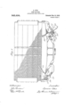
- FIG. 1 is an end view of a dump car embodying my improvement.
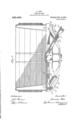
- Fig. 2 is a cross section of such a car.
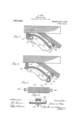
- Figs. 3 and 4 are elevations of a detail showing certain essential elements of my invention at two different operating positions.
- Fig. 5 is a bottom view of the member designated 20, and
- Fig. 6 is a cross section of Fig. 3 on the line 6-6.
- a gondola car is provided with dumping floor sections 15. Between successive floor sections beneath the car floor are the depending inclined tracks 16, each having a level portion 16' at its upper and outer end. Each track 16 hangs from the car framework by vertical end portions 18 and 18. The longitudinal shaft 17 rests on the track 16 and the doors 15 in turn are supported by the shaft 17.
- each inclined track 16 has forked ends 19' and 20'.
- the character of this member will be best understood from Figs. 3, 4: and 5.
- the fork 19 pivotally engages the depending portion 18 of the inclined track, while the fork 20 at the other end engages the other depending portion 18 of the vertical track, the last described engagement serving to guide the rotary movement of the member 20 about the pivot 19.
- Gear teeth 21 are cut in the under surface of the member 20 so as to form a rack. Engaging this rack 21 at its sides are the two gear pinions 23 fixed on the shaft 17 on either side of the track 16.
- the mechanism for producing rotation and consequent reciprocation of shaft 17 may be of the character shown in Fig. 1, in which 2 1 is a ratchet wheel fixed on the end of the shaft 17. 25 is a crank or lever loosely engaging the shaft at one end and carrying a pawl 26 which is adapted to engage the said ratchet wheel 24:.
- the shaft 17 also has loosely sleeved thereon a carriage or plate 27 which has a sliding engagement with the inclined track 16 and also carries a dog 28 adapted to look into the ratchet wheel 24.
- the lever 25 may be used to rotate the shaft 17 and that the latter can be locked against rotation in any desired position by means of the dog 28.
- a reciprocatory door operating shaft a supporting track therefor, said track depending by terminal vertical portions from the framework of the car, a member longitudinally overhanging said track, said member being pivoted at one end to the vertical portion of the track at that end, and means of engagement between the shaft and the member.
- a reciprocatory door operating shaft In a dump car, a reciprocatory door operating shaft, a supporting track therefor, said track depending by terminal vertical portions from the framework of the car, a member longitudinally overhanging said track, said member having forked ends ongaging the respective vertical portions of the track, and means for the shaft to engage the member.
- a reciprocatory door operating shaft In a dump car, a reciprocatory door operating shaft, a supporting track therefor, a member pivoted at one end and longitudinally overhanging said track, and means of engagement between the shaft and the said member.
- a reciprocatory door operating shaft an inclined supporting track therefor, a gear Wheel on said shaft, a rack above and engaging said gear Wheel, said rack having a. limited vertical movement, but being fixed against movement in the direction of reciprocation of said shaft.
Landscapes
- Engineering & Computer Science (AREA)
- Transportation (AREA)
- Mechanical Engineering (AREA)
- Elevator Door Apparatuses (AREA)
Description
S. OTIS.
DUMP GAR DOOR. APPLICATION FILED JUNE 18, 1908.
Patented Feb. 15, 1910.
3 SHEETS-SHEET 1.
A 11mm N v w w pu /wet S. OTIS.
DUMP GAR DOOR. APPIQIOATION FILED JUNE 18, 1908.
949,494. Patented Feb. 15,1910.
3SHEBTS-SHEET 2.
[0 0o 0O 0O Milo ,0 0 I I g lo 00 oo L f I11 I g S. OTIS DUMP GAR DOOR. APPLICATION 11,211 JUNE 19, 190B.
949,494 Patented Feb.15.1910.
3 SHEETS-SHEET 3.
SPENCER OTIS, OF CHICAGO, ILLINOIS, ASSIGNOR TO NATIONAL DUMP CAR COMPANY, A CORPORATION OF MAINE.
DUMP-CAR. DOOR.
eaaaaa.
To all whom it may concern:
Be it known that I, SPENCER OTIS, a citizen of the United States, residing at Chicago, in the county of Cook and State of Illinois, have invented certain new and useful Improvements in Dump-Gar Doors, of which the following is a specification.
The object of my invention is to provide a new and improved operating mechanism for dump car doors.
Another object is to provide such a mechanism that shall be arranged to prevent interference from dirt and debris falling down on it from above.
These objects and various others will be made apparent in the following specification and claims, when taken in connection with the accompanying drawings, in which Figure 1 is an end view of a dump car embodying my improvement. Fig. 2 is a cross section of such a car. Figs. 3 and 4 are elevations of a detail showing certain essential elements of my invention at two different operating positions. Fig. 5 is a bottom view of the member designated 20, and Fig. 6 is a cross section of Fig. 3 on the line 6-6.
In the particular embodiment of my invention which I have chosen to illustrate and describe in this specification, a gondola car is provided with dumping floor sections 15. Between successive floor sections beneath the car floor are the depending inclined tracks 16, each having a level portion 16' at its upper and outer end. Each track 16 hangs from the car framework by vertical end portions 18 and 18. The longitudinal shaft 17 rests on the track 16 and the doors 15 in turn are supported by the shaft 17.
Directly above each inclined track 16 lies a member 20 having forked ends 19' and 20'. The character of this member will be best understood from Figs. 3, 4: and 5. The fork 19 pivotally engages the depending portion 18 of the inclined track, while the fork 20 at the other end engages the other depending portion 18 of the vertical track, the last described engagement serving to guide the rotary movement of the member 20 about the pivot 19. Gear teeth 21 are cut in the under surface of the member 20 so as to form a rack. Engaging this rack 21 at its sides are the two gear pinions 23 fixed on the shaft 17 on either side of the track 16. It
Specification of Letters Patent.
Application filed. June 18, 1908.
Serial No. 439,134.
will at once be seen that rotation of the shaft 17 will cause it to slide along the track 16 by reason of the co-action between the gear pinions 23 on the shaft 17 and the rack 21 on the member 20. Such reciprocation of shaft 17 will obviously actuate the doors 15 to open or close them.
The mechanism for producing rotation and consequent reciprocation of shaft 17 may be of the character shown in Fig. 1, in which 2 1 is a ratchet wheel fixed on the end of the shaft 17. 25 is a crank or lever loosely engaging the shaft at one end and carrying a pawl 26 which is adapted to engage the said ratchet wheel 24:. The shaft 17 also has loosely sleeved thereon a carriage or plate 27 which has a sliding engagement with the inclined track 16 and also carries a dog 28 adapted to look into the ratchet wheel 24. It will readily be seen that the lever 25 may be used to rotate the shaft 17 and that the latter can be locked against rotation in any desired position by means of the dog 28.
It will be seen that I have invented a door operating mechanism which, in addition to simplicity of structure and operation, is adapted to shield the mechanism from becoming clogged up with dirt falling down from above. The rack teeth 21, the gear teeth 23 and the track 16 are all overhung by the pivoted member 20.
I claim:
1. In a dump car, a reciprocatory door operating shaft, a supporting track therefor, said track depending by terminal vertical portions from the framework of the car, a member longitudinally overhanging said track, said member being pivoted at one end to the vertical portion of the track at that end, and means of engagement between the shaft and the member.
2. In a dump car, a reciprocatory door operating shaft, a supporting track therefor, said track depending by terminal vertical portions from the framework of the car, a member longitudinally overhanging said track, said member having forked ends ongaging the respective vertical portions of the track, and means for the shaft to engage the member.
3. In a dump car, a reciprocatory door operating shaft, a supporting track therefor, a member pivoted at one end and trans- Iateinted Feb. 15, 1910.
versely overhanging the shaft and means of engagement between the shaft and the said member.
4. In a dump car, a reciprocatory door operating shaft, a supporting track therefor, a member pivoted at one end and longitudinally overhanging said track, and means of engagement between the shaft and the said member.
5. In a dump car, a reciprocatory door operating shaft, an inclined supporting track therefor, a gear Wheel on said shaft, a rack above and engaging said gear Wheel, said rack having a. limited vertical movement, but being fixed against movement in the direction of reciprocation of said shaft.
In testimony whereof, I have subscribed my name. i
SPENCER OTIS.
Witnesses:
EDYTHE M. ANDERSON, LILLIAN A. KIBBY.
Priority Applications (1)
| Application Number | Priority Date | Filing Date | Title |
|---|---|---|---|
| US43913408A US949494A (en) | 1908-06-18 | 1908-06-18 | Dump-car door. |
Applications Claiming Priority (1)
| Application Number | Priority Date | Filing Date | Title |
|---|---|---|---|
| US43913408A US949494A (en) | 1908-06-18 | 1908-06-18 | Dump-car door. |
Publications (1)
| Publication Number | Publication Date |
|---|---|
| US949494A true US949494A (en) | 1910-02-15 |
Family
ID=3017908
Family Applications (1)
| Application Number | Title | Priority Date | Filing Date |
|---|---|---|---|
| US43913408A Expired - Lifetime US949494A (en) | 1908-06-18 | 1908-06-18 | Dump-car door. |
Country Status (1)
| Country | Link |
|---|---|
| US (1) | US949494A (en) |
Cited By (1)
| Publication number | Priority date | Publication date | Assignee | Title |
|---|---|---|---|---|
| US3138116A (en) * | 1960-12-09 | 1964-06-23 | Entpr Railway Equipment Co | Sliding hopper closure outlet assembly |
-
1908
- 1908-06-18 US US43913408A patent/US949494A/en not_active Expired - Lifetime
Cited By (1)
| Publication number | Priority date | Publication date | Assignee | Title |
|---|---|---|---|---|
| US3138116A (en) * | 1960-12-09 | 1964-06-23 | Entpr Railway Equipment Co | Sliding hopper closure outlet assembly |
Similar Documents
| Publication | Publication Date | Title |
|---|---|---|
| US3468062A (en) | Boxcar door control | |
| US3613312A (en) | Railway car plug door structure | |
| US937101A (en) | Dump-door-operating mechanism. | |
| US988310A (en) | Dump-car. | |
| US706833A (en) | Trap-door for car-platforms. | |
| US1651064A (en) | Starting and closing means for doors | |
| US966603A (en) | Locking mechanism for railway dump-cars. | |
| US1100184A (en) | Safety appliance for mine-shafts. | |
| US857291A (en) | Switch-stand. | |
| US739914A (en) | Bottom-dumping car. | |
| US801459A (en) | Transportation-car of the drop-bottom-gondola type. | |
| US923961A (en) | Car-door. | |
| US773002A (en) | Car-platform-operating device. | |
| US1308418A (en) | Planoqrapji co | |
| US1617576A (en) | of chicago | |
| US1103008A (en) | Double-folding car-step. | |
| US973874A (en) | Dumping-door-operating mechanism. | |
| US1028415A (en) | Car-door-operating mechanism. | |
| US649344A (en) | Car-door. | |
| US1608366A (en) | Carrier | |
| US959459A (en) | Door-operating mechanism for dump-cars. | |
| US1255385A (en) | Door-operating mechanism. | |
| US1067548A (en) | Grain-door. | |
| US942927A (en) | Railway switch mechanism. | |
| US904213A (en) | Door-operating mechanism for dump-cars. |