US9494768B2 - Image capturing module and image capturing apparatus - Google Patents
Image capturing module and image capturing apparatus Download PDFInfo
- Publication number
- US9494768B2 US9494768B2 US14/549,315 US201414549315A US9494768B2 US 9494768 B2 US9494768 B2 US 9494768B2 US 201414549315 A US201414549315 A US 201414549315A US 9494768 B2 US9494768 B2 US 9494768B2
- Authority
- US
- United States
- Prior art keywords
- image
- band
- narrow
- wavelength
- image capturing
- Prior art date
- Legal status (The legal status is an assumption and is not a legal conclusion. Google has not performed a legal analysis and makes no representation as to the accuracy of the status listed.)
- Expired - Fee Related
Links
- 238000001228 spectrum Methods 0.000 claims description 13
- 230000003287 optical effect Effects 0.000 claims description 5
- 238000012545 processing Methods 0.000 description 36
- 238000010586 diagram Methods 0.000 description 10
- 238000012937 correction Methods 0.000 description 6
- 238000012986 modification Methods 0.000 description 5
- 230000004048 modification Effects 0.000 description 5
- 230000008901 benefit Effects 0.000 description 4
- 238000005516 engineering process Methods 0.000 description 3
- 230000003595 spectral effect Effects 0.000 description 3
- XUMBMVFBXHLACL-UHFFFAOYSA-N Melanin Chemical compound O=C1C(=O)C(C2=CNC3=C(C(C(=O)C4=C32)=O)C)=C2C4=CNC2=C1C XUMBMVFBXHLACL-UHFFFAOYSA-N 0.000 description 2
- 230000000694 effects Effects 0.000 description 2
- 238000002594 fluoroscopy Methods 0.000 description 2
- 238000000034 method Methods 0.000 description 2
- 102000001554 Hemoglobins Human genes 0.000 description 1
- 108010054147 Hemoglobins Proteins 0.000 description 1
- 238000013459 approach Methods 0.000 description 1
- BJQHLKABXJIVAM-UHFFFAOYSA-N bis(2-ethylhexyl) phthalate Chemical compound CCCCC(CC)COC(=O)C1=CC=CC=C1C(=O)OCC(CC)CCCC BJQHLKABXJIVAM-UHFFFAOYSA-N 0.000 description 1
- 239000003086 colorant Substances 0.000 description 1
- 238000005286 illumination Methods 0.000 description 1
- 238000004519 manufacturing process Methods 0.000 description 1
- 230000002265 prevention Effects 0.000 description 1
- 238000002834 transmittance Methods 0.000 description 1
Images


Classifications
-
- G—PHYSICS
- G02—OPTICS
- G02B—OPTICAL ELEMENTS, SYSTEMS OR APPARATUS
- G02B13/00—Optical objectives specially designed for the purposes specified below
- G02B13/001—Miniaturised objectives for electronic devices, e.g. portable telephones, webcams, PDAs, small digital cameras
- G02B13/0055—Miniaturised objectives for electronic devices, e.g. portable telephones, webcams, PDAs, small digital cameras employing a special optical element
-
- A—HUMAN NECESSITIES
- A61—MEDICAL OR VETERINARY SCIENCE; HYGIENE
- A61B—DIAGNOSIS; SURGERY; IDENTIFICATION
- A61B5/00—Measuring for diagnostic purposes; Identification of persons
- A61B5/0059—Measuring for diagnostic purposes; Identification of persons using light, e.g. diagnosis by transillumination, diascopy, fluorescence
- A61B5/0077—Devices for viewing the surface of the body, e.g. camera, magnifying lens
-
- A—HUMAN NECESSITIES
- A61—MEDICAL OR VETERINARY SCIENCE; HYGIENE
- A61B—DIAGNOSIS; SURGERY; IDENTIFICATION
- A61B5/00—Measuring for diagnostic purposes; Identification of persons
- A61B5/103—Measuring devices for testing the shape, pattern, colour, size or movement of the body or parts thereof, for diagnostic purposes
- A61B5/1032—Determining colour of tissue for diagnostic purposes
-
- G—PHYSICS
- G01—MEASURING; TESTING
- G01J—MEASUREMENT OF INTENSITY, VELOCITY, SPECTRAL CONTENT, POLARISATION, PHASE OR PULSE CHARACTERISTICS OF INFRARED, VISIBLE OR ULTRAVIOLET LIGHT; COLORIMETRY; RADIATION PYROMETRY
- G01J3/00—Spectrometry; Spectrophotometry; Monochromators; Measuring colours
- G01J3/02—Details
- G01J3/0205—Optical elements not provided otherwise, e.g. optical manifolds, diffusers, windows
- G01J3/0208—Optical elements not provided otherwise, e.g. optical manifolds, diffusers, windows using focussing or collimating elements, e.g. lenses or mirrors; performing aberration correction
-
- G—PHYSICS
- G01—MEASURING; TESTING
- G01J—MEASUREMENT OF INTENSITY, VELOCITY, SPECTRAL CONTENT, POLARISATION, PHASE OR PULSE CHARACTERISTICS OF INFRARED, VISIBLE OR ULTRAVIOLET LIGHT; COLORIMETRY; RADIATION PYROMETRY
- G01J3/00—Spectrometry; Spectrophotometry; Monochromators; Measuring colours
- G01J3/28—Investigating the spectrum
- G01J3/2823—Imaging spectrometer
-
- G—PHYSICS
- G01—MEASURING; TESTING
- G01J—MEASUREMENT OF INTENSITY, VELOCITY, SPECTRAL CONTENT, POLARISATION, PHASE OR PULSE CHARACTERISTICS OF INFRARED, VISIBLE OR ULTRAVIOLET LIGHT; COLORIMETRY; RADIATION PYROMETRY
- G01J3/00—Spectrometry; Spectrophotometry; Monochromators; Measuring colours
- G01J3/28—Investigating the spectrum
- G01J3/30—Measuring the intensity of spectral lines directly on the spectrum itself
- G01J3/36—Investigating two or more bands of a spectrum by separate detectors
-
- G—PHYSICS
- G01—MEASURING; TESTING
- G01J—MEASUREMENT OF INTENSITY, VELOCITY, SPECTRAL CONTENT, POLARISATION, PHASE OR PULSE CHARACTERISTICS OF INFRARED, VISIBLE OR ULTRAVIOLET LIGHT; COLORIMETRY; RADIATION PYROMETRY
- G01J3/00—Spectrometry; Spectrophotometry; Monochromators; Measuring colours
- G01J3/46—Measurement of colour; Colour measuring devices, e.g. colorimeters
- G01J3/50—Measurement of colour; Colour measuring devices, e.g. colorimeters using electric radiation detectors
- G01J3/51—Measurement of colour; Colour measuring devices, e.g. colorimeters using electric radiation detectors using colour filters
- G01J3/513—Measurement of colour; Colour measuring devices, e.g. colorimeters using electric radiation detectors using colour filters having fixed filter-detector pairs
-
- G—PHYSICS
- G02—OPTICS
- G02B—OPTICAL ELEMENTS, SYSTEMS OR APPARATUS
- G02B27/00—Optical systems or apparatus not provided for by any of the groups G02B1/00 - G02B26/00, G02B30/00
- G02B27/10—Beam splitting or combining systems
- G02B27/1006—Beam splitting or combining systems for splitting or combining different wavelengths
- G02B27/1013—Beam splitting or combining systems for splitting or combining different wavelengths for colour or multispectral image sensors, e.g. splitting an image into monochromatic image components on respective sensors
-
- H—ELECTRICITY
- H04—ELECTRIC COMMUNICATION TECHNIQUE
- H04N—PICTORIAL COMMUNICATION, e.g. TELEVISION
- H04N23/00—Cameras or camera modules comprising electronic image sensors; Control thereof
- H04N23/70—Circuitry for compensating brightness variation in the scene
- H04N23/749—Circuitry for compensating brightness variation in the scene by influencing the pick-up tube voltages
-
- H—ELECTRICITY
- H04—ELECTRIC COMMUNICATION TECHNIQUE
- H04N—PICTORIAL COMMUNICATION, e.g. TELEVISION
- H04N25/00—Circuitry of solid-state image sensors [SSIS]; Control thereof
- H04N25/10—Circuitry of solid-state image sensors [SSIS]; Control thereof for transforming different wavelengths into image signals
- H04N25/11—Arrangement of colour filter arrays [CFA]; Filter mosaics
- H04N25/13—Arrangement of colour filter arrays [CFA]; Filter mosaics characterised by the spectral characteristics of the filter elements
- H04N25/134—Arrangement of colour filter arrays [CFA]; Filter mosaics characterised by the spectral characteristics of the filter elements based on three different wavelength filter elements
-
- H—ELECTRICITY
- H04—ELECTRIC COMMUNICATION TECHNIQUE
- H04N—PICTORIAL COMMUNICATION, e.g. TELEVISION
- H04N25/00—Circuitry of solid-state image sensors [SSIS]; Control thereof
- H04N25/10—Circuitry of solid-state image sensors [SSIS]; Control thereof for transforming different wavelengths into image signals
- H04N25/11—Arrangement of colour filter arrays [CFA]; Filter mosaics
- H04N25/13—Arrangement of colour filter arrays [CFA]; Filter mosaics characterised by the spectral characteristics of the filter elements
- H04N25/135—Arrangement of colour filter arrays [CFA]; Filter mosaics characterised by the spectral characteristics of the filter elements based on four or more different wavelength filter elements
-
- H04N5/2358—
-
- H04N9/045—
-
- A—HUMAN NECESSITIES
- A61—MEDICAL OR VETERINARY SCIENCE; HYGIENE
- A61B—DIAGNOSIS; SURGERY; IDENTIFICATION
- A61B2562/00—Details of sensors; Constructional details of sensor housings or probes; Accessories for sensors
- A61B2562/02—Details of sensors specially adapted for in-vivo measurements
- A61B2562/0233—Special features of optical sensors or probes classified in A61B5/00
-
- G—PHYSICS
- G01—MEASURING; TESTING
- G01J—MEASUREMENT OF INTENSITY, VELOCITY, SPECTRAL CONTENT, POLARISATION, PHASE OR PULSE CHARACTERISTICS OF INFRARED, VISIBLE OR ULTRAVIOLET LIGHT; COLORIMETRY; RADIATION PYROMETRY
- G01J3/00—Spectrometry; Spectrophotometry; Monochromators; Measuring colours
- G01J3/28—Investigating the spectrum
- G01J3/2823—Imaging spectrometer
- G01J2003/2826—Multispectral imaging, e.g. filter imaging
-
- H—ELECTRICITY
- H04—ELECTRIC COMMUNICATION TECHNIQUE
- H04N—PICTORIAL COMMUNICATION, e.g. TELEVISION
- H04N2209/00—Details of colour television systems
- H04N2209/04—Picture signal generators
- H04N2209/041—Picture signal generators using solid-state devices
- H04N2209/042—Picture signal generators using solid-state devices having a single pick-up sensor
- H04N2209/047—Picture signal generators using solid-state devices having a single pick-up sensor using multispectral pick-up elements
Definitions
- the present invention relates to an image capturing module and an image capturing apparatus.
- Patent Literature 1 image acquisition of a wide-band image and a narrow-band image is performed using a digital camera for RGB color image acquisition.
- a digital camera for RGB color image acquisition.
- the image acquisition takes time because illumination light of different colors is radiated sequentially.
- the shape of the subject changes between the RGB image and the narrow-band image, or between narrow-band images.
- An aspect of the present invention is an image capturing module including a microlens array that collects light from a subject, which is imaged at an image plane; a filter that allows light in specific wavelength bands in the light collected by the microlens array to pass therethrough; and an image capturing device that acquires images of the light passing through the filter, wherein the filter is formed by arraying a plurality of RGB filter portions that pass light in RGB wavelength bands and a plurality of narrow-band filter portions that pass light in wavelength bands that are narrower than the RGB wavelength bands, the image capturing device includes a plurality of color-wavelength obtaining regions that acquire images of the light passing through the RGB filter portions and a plurality of narrow-band-wavelength obtaining regions that acquire images of the light passing through the narrow-band filter portions, and the microlens array includes a plurality of first microlenses that are disposed in correspondence with the respective color-wavelength obtaining regions and a plurality of second microlenses that are disposed in correspondence with the respective narrow-band-wavelength
- FIG. 1 is a longitudinal sectional view showing an image capturing module according to an embodiment of the present invention.
- FIG. 2 is a front view for explaining an image capturing device and an array of image-capturing region units and microlenses in the image capturing module in FIG. 1 .
- FIG. 3 is a diagram for explaining the relationship between the image-capturing region unit and the microlenses in FIG. 2 .
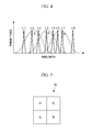
- FIG. 4 is a diagram showing the transmittance characteristics of RGB filter portions and narrow-band filter portions in a filter of the image-capturing module in FIG. 1 .
- FIG. 5 is a diagram showing an RGB Bayer array as an example of the RGB filter portions in the filter of the image-capturing module in FIG. 1 .
- FIG. 6 is a diagram showing the overall configuration of an image capturing apparatus according to an embodiment of the present invention, which is provided with the image capturing module in FIG. 1 .
- FIG. 7 is a block diagram for explaining the details of a display-image generating portion of the image capturing apparatus in FIG. 6 .
- FIG. 8A is a diagram showing an example RGB image acquired by the image capturing apparatus in FIG. 6 .
- FIG. 8B is a diagram showing an example of a combined image acquired by the image capturing apparatus in FIG. 6 , in which a narrow-band image and an RGB image are superimposed.
- FIG. 9 is a longitudinal sectional view showing a modification of the image capturing module in FIG. 1 .
- FIG. 10 is a block diagram showing a modification of the display-image generating portion in FIG. 6 .
- FIG. 11 is a diagram showing a modification of the image-capturing region unit and microlenses in FIG. 3 .
- FIG. 12 is a longitudinal sectional view showing an image capturing module having the image-capturing region unit and microlenses in FIG. 11 .
- FIG. 13 is a longitudinal sectional view showing a first modification of the image capturing module in FIG. 12 .
- FIG. 14 is a longitudinal sectional view showing a second modification of the image capturing module in FIG. 12 .
- FIG. 15 is a longitudinal sectional view showing a first way of improving the spectral precision in etalons serving as the narrow-band filter portions.
- FIG. 16 is a longitudinal sectional view showing a second way of improving the spectral precision in etalons serving as the narrow-band filter portions.
- the image capturing module 1 includes a microlens array 2 , a filter 3 , and an image capturing device 4 .
- microlenses first microlens 2 a and second microlenses 2 b ) are disposed in correspondence with the partial regions 4 a and 4 b.
- the center partial region 4 a is a color-wavelength obtaining region that acquires an image of light in RGB wavelength bands (hereinafter referred to as color-wavelength obtaining region 4 a ), and the eight partial regions 4 b surrounding the color-wavelength obtaining region 4 a are narrow-band-wavelength obtaining regions that respectively acquire images of light in eight wavelength bands ⁇ 1 to ⁇ 8, which are sufficiently narrower than the RGB wavelength bands (hereinafter referred to as narrow-band-wavelength obtaining regions 4 b ).
- the individual microlenses 2 a and 2 b that constitute the microlens array 2 have a reduction factor of 3, as shown in FIG. 1 .
- the microlenses 2 a and 2 b are disposed a distance d away from the image capturing plane B and a distance 3 d away from the image plane A.
- the filter 3 includes RGB filter portions 3 a that cover the color-wavelength obtaining regions 4 a of the image capturing device 4 and narrow-band filter portions 3 b 1 to 3 b 8 that respectively cover the other eight narrow-band-wavelength obtaining regions 4 b.
- red (R), green (G), and blue (B) color filters are disposed in the form of 2 ⁇ 2 neighboring pixels, thus forming a so-called RGB Bayer array filter.
- the filters of each color are configured so as to transmit light in comparatively wide wavelength bands.
- the narrow-band filter portions 3 b 1 to 3 b 8 are provided with reflective films (not illustrated) on the two flat surfaces thereof, which are disposed parallel to each other with a gap therebetween, thus forming spectral filters known as etalons, and as shown in FIG. 4 , are configured so as to be capable of selectively transmitting light in extremely narrow wavelength bands ⁇ 1 to ⁇ 8, and so that the wavelength bands that are transmitted can be made different depending on the gap between the reflective films.
- the narrow-band filter portions 3 b 1 to 3 b 8 respectively disposed in the eight narrow-band-wavelength obtaining regions 4 b are configured so as to respectively transmit light in the different wavelength bands ⁇ 1 to ⁇ 8 by, for example, making the gaps between the reflective films different.
- the filter portions 3 a and 3 b 1 to 3 b 8 of the same kind, which transmit light in the same wavelength band, are disposed at a three-filter period in both the row direction and the column direction.
- the reduction factors of the microlenses 2 a and 2 b are set to 3, as shown in FIG.
- the light from the subject which is imaged at the image plane A of the image capturing lens, arrives at every one of the wavelength obtaining regions 4 a and 4 b , for the filter portions 3 a and 3 b 1 to 3 b 8 of all kinds (in FIG. 1 , wavelength bands ⁇ 3 and ⁇ 6 and RGB are shown, but the others are omitted).
- the image capturing module 1 since the image of the subject imaged at the image plane A of the image capturing lens is split into a plurality of partial images by the microlens array 2 and multiple images are obtained by the plurality of wavelength obtaining regions 4 a and 4 b of the image capturing device 4 , it is possible to simultaneously obtain an RGB image and narrow-band images of the subject; as a result, an advantage is afforded in that, when this RGB image and narrow-band images are combined, it is possible to obtain a clear blur-free image, even for a moving subject.
- the image capturing apparatus 10 includes an image capturing lens 11 that forms an image at the image plane A by focusing light coming from the subject; the above-described image capturing module 1 ; an image processing portion 12 ; a finder 13 ; a monitor 14 ; and an observation-conditions setting portion 15 .
- the image processing portion 12 includes an A/D converter 16 that converts an image signal formed of an analog signal obtained by the image capturing device 4 of the image capturing module 1 to a digital signal; an image-joining processing portion (RGB-image-information creating portion, narrow-band-image-information creating portion) 17 that creates RGB image information and eight items of narrow-band image information by joining image signals obtained by the same kind of wavelength obtaining regions 4 a and 4 b of the image capturing device 4 ; a buffer 18 that temporarily stores the created image information; and a display-image generating portion 19 that creates image information to be displayed, by using the image information stored in the buffer 18 .
- RGB-image-information creating portion, narrow-band-image-information creating portion 17 that creates RGB image information and eight items of narrow-band image information by joining image signals obtained by the same kind of wavelength obtaining regions 4 a and 4 b of the image capturing device 4
- a buffer 18 that temporarily stores the created image information
- a display-image generating portion 19 that creates image information to
- the display-image generating portion 19 includes an RGB-image processing portion 20 that processes the RGB image information and a narrow-band-image processing portion 21 that combines the RGB image information processed in the RGB-image processing portion 20 and the narrow-band image information.
- the observation-conditions setting portion 15 is configured so that the observer can specify the image acquisition conditions for the image capturing device 4 , such as the angle of view and the exposure, and the observation conditions, such as which narrow-band image information of the wavelength bands ⁇ 1 to ⁇ 8 among the eight items of narrow-band image information is to be combined.
- the RGB-image processing portion 20 includes a white-balance correction portion 22 that performs white-balance correction processing on the RGB image information sent from the buffer 18 ; an RGB demosaicing portion 23 that performs demosaicing processing; a grayscale correction portion 24 that performs grayscale correction processing; a color correction portion 25 that performs color correction processing; and a noise-removal processing portion 26 that performs noise-removal processing.
- the RGB image information processed in the RGB-image processing portion 20 is output to the finder 13 and the narrow-band-image processing portion 21 .
- the narrow-band-image processing portion 21 includes a wavelength selection portion 27 that selects the narrow-band image information for the wavelength band specified by the observation-conditions setting portion 15 and an image combining portion 28 that combines the narrow-band image information selected in the wavelength selection portion 27 and the RGB image information input from the RGB-image processing portion 20 .
- the combined image created in the image combining portion 28 is output to the monitor 14 .
- the finder 13 which is, for example, an electronic viewfinder, is provided in an eyepiece unit (not illustrated) and is configured to present the RGB image sent from the RGB-image processing portion 20 to the eye of the observer.
- the image capturing apparatus 10 After the light coming from the subject, which is focused by the image capturing lens 11 , is imaged at the image plane A, it is collected by the microlens array 2 of the image capturing module 1 and is obtained by the plurality of wavelength obtaining regions 4 a and 4 b of the image capturing device 4 in the form of partial image signals of the subject, which overlap with each other.
- the partial image signals of the subject, obtained by the image capturing device 4 are converted to digital signals by the A/D converter 16 , whereupon, in the image-joining processing portion 17 , they are joined together for each of the wavelength obtaining regions that obtained these partial image signals, thus creating the RGB image information and the eight items of narrow-band image information.
- the RGB image information created in the image-joining processing portion 17 is sent to the RGB-image processing portion 20 in the display-image generating portion 19 , where various types of processing are performed thereon, and the RGB image information to be displayed is created.
- the created RGB image information is sent to the finder 13 and the narrow-band-image processing portion 21 .
- the narrow-band image information created in the image-joining processing portion 17 is sent to the narrow-band-image processing portion 21 in the display-image generating portion 19 .
- the observer can adjust the image acquisition conditions, such as the angle of view and the exposure.
- the observer selects one of the wavelength bands ⁇ 1 to ⁇ 8 that he or she wishes to observe in a superimposed manner on the RGB image.
- the observation-conditions setting portion 15 besides selection of the wavelength band for the narrow-band image to be observed in a superimposed manner on the RGB image, it is possible to specify whether to observe the RGB image without superimposing the narrow-band image thereon, or whether to observe only the selected narrow-band image, without superimposing the RGB image thereon.
- the observation-conditions setting portion 15 is also connected to an image-capturing control portion 29 that controls the image capturing module 1 , and, when the observation conditions are set via the observation-conditions setting portion 15 , the image-capturing control portion 29 controls the image capturing module 1 so as to acquire an image of the subject with the set observation conditions, and an RGB image signal and narrow-band image signals are obtained.
- the obtained RGB image signal and narrow-band image signals are converted to digital signals by the A/D converter 16 , and then the RGB image information and eight items of narrow-band image information are created in the image-joining processing portion 17 and are sent to the display-image generating portion 19 .
- the RGB image information is processed in the RGB-image processing portion 20 and is sent to the finder 13 , and is also sent to the narrow-band-image processing portion 21 . Also, in the narrow-band-image processing portion 21 , when the wavelength band for the narrow-band image information to be superimposed is specified in the observation-conditions setting portion 15 , the narrow-band image information corresponding to the specified wavelength band is selected in the wavelength selection portion 27 .
- the image combining portion 28 color processing, for example, for enhancement, is performed on the narrow-band image information selected in the wavelength selection portion 27 , and the RGB image information sent from the RGB-image processing portion 20 is combined therewith.
- the combined image combined in the image combining portion 28 is output to the monitor 14 and is displayed thereon.
- FIG. 8A and FIG. 8B Schematic diagrams for the case where only the RGB image is displayed and the case where a narrow-band image of a prescribed wavelength band (for example, a center wavelength of 550 nm and a wavelength width of 10 nm) is enhanced and superimposed on the RGB image are shown in FIG. 8A and FIG. 8B , respectively.
- a skin condition that is not clear in the RGB image alone in FIG. 8A is clearly visible in FIG. 8B .
- the image capturing apparatus 10 since the RGB image signal constituting the RGB image information and the narrow-band image signal constituting the narrow-band image information are simultaneously obtained by the image capturing module 1 , an advantage is afforded in that, even if these items of image information are superimposed, there is no positional shift between images, and it is possible to obtain a blur-free clear combined image.
- the image capturing apparatus 10 according to this embodiment since the RGB image information and the narrow-band image information are both obtained by the image-capturing module 1 without any loss, an advantage is afforded in that it is possible to observe the subject without overlooking any information about the subject.
- the reduction factor is set to 3; instead of this, however, a reduction factor slightly larger than 3, for example, 3.1 (though it is not limited thereto) may be used, as shown in FIG. 9 .
- a reduction factor slightly larger than 3 for example, 3.1 (though it is not limited thereto) may be used, as shown in FIG. 9 .
- the image capturing apparatus 10 has been described in terms of an example in which the narrow-band-image processing portion 21 provided in the display-image generating portion 19 has the image combining portion 28 that combines the RGB image information and the selected narrow-band image information in a superimposed manner.
- this image combining portion 28 instead of this image combining portion 28 , however, one having an image switching portion (not illustrated) that outputs the RGB image information and the narrow-band image information to the monitor 14 in an alternating manner may be employed. By doing so, even in the case where an image of a moving subject is acquired, it is possible to observe the subject without generating a positional shift between the alternating images.
- the wavelength selection portion 27 in the narrow-band-image processing portion 21 selects a single item of narrow-band image information, instead of this, it may select a plurality of items of narrow-band image information, which may be combined in the image combining portion 28 .
- the wavelength selection portion 27 in the narrow-band-image processing portion 21 selects a single item of narrow-band image information, instead of this, it may select a plurality of items of narrow-band image information, which may be combined in the image combining portion 28 .
- the wavelength selection portion 27 in the narrow-band-image processing portion 21 selects a single item of narrow-band image information
- RGB image information and narrow-band image information are superimposed
- a unit that combines the RGB image information and the narrow-band image information in such a manner that they are displayed side-by-side may be employed.
- the narrow-band-image processing portion 21 may have a spectrum estimating portion 30 that estimates pixel values in other wavelength bands at each pixel from the acquired narrow-band images for the eight wavelength bands.
- the spectrum estimating portion 30 estimates the pixel value at each pixel in other wavelength bands based on the pixel values in eight different wavelength bands, even when a wavelength region other than the eight wavelength bands is specified in the wavelength selection portion 27 , it is possible to select a narrow-band image in this other specified wavelength band by using pixel values estimated by the spectrum estimating portion 30 .
- Such a configuration can be employed in the case where it is necessary to detect the presence or absence of a signal, without the need for high resolution, as in fluoroscopy.
- the narrow-band-wavelength obtaining regions 4 b constitute 1/16 of the entire image capturing device 4 , resulting in 1 ⁇ 4 of the resolution compared with the color-wavelength obtaining regions 4 a , this configuration is effective in applications where high resolution is not necessary, such as fluoroscopy.
- the positional relationships of the first microlens 2 a and the second microlenses 2 b in the optical-axis direction relative to the image capturing device 4 should be made different, so that the focal positions are all made coincident with the image plane A of the image capturing lens 11 , while achieving reduction factors of 2 and 4, respectively.
- the positions of the first and second microlenses 2 a and 2 b in the optical-axis direction are all the same, and a step is provided at an image capturing plane B of the image capturing device 4 so that the positions of the color-wavelength obtaining region 4 a and the narrow-band-wavelength obtaining regions 4 b in the optical-axis direction are made to be different.
- the image capturing plane B of the image capturing device 4 is entirely at the same position, and the positions of the first microlens 2 a and the second microlenses 2 b in the optical-axis direction are made to be different.
- the second microlenses which have larger reduction factors and shorter focal lengths, are brought closer to the image capturing plane, making it possible to obtain an in-focus narrow-band image.
- making the positions of the microlenses 2 a and 2 b in the optical-axis direction all the same, as shown in FIG. 13 simplifies their fabrication.
- the wavelength that is transmitted changes according to the angle of incidence of the light, and therefore, it is preferable to make the light incident at an angle of incidence as close as possible to 90°.
- apertures 31 may be provided between the microlenses 2 a and 2 b and the narrow-band filter portions 3 b 1 to 3 b 8 , so that only light having an angle of incidence close to 90° in the incident light is made incident on the filter 3 . Accordingly, it is possible to make the angle of incidence of the light that is incident on the narrow-band filter portions 3 b 1 to 3 b 12 close to 90°, so that light in the desired wavelength band can be allowed to pass therethrough with high precision.
- microlenses that collimate the light from the subject and cause substantially collimated beams to be incident on the filter 3 may be employed as the microlenses 2 a and 2 b , as shown in FIG. 16 .
- the angle of incidence of the light falling on the filter 3 it is possible to set the angle of incidence of the light falling on the filter 3 to substantially 90°.
- image capturing module 1 has been illustrated in terms of image-capturing region units PiQj formed of 3 ⁇ 3 partial regions 4 a and 4 b and image-capturing region units PiQj formed of 4 ⁇ 4 partial regions 4 a and 4 b , in general, a configuration in which image-capturing region units PiQj formed of n ⁇ n (where n is an integer equal to or greater than 2) partial regions 4 a and 4 b are repeatedly arrayed may be used.
- microlenses 2 a and 2 b corresponding to the partial regions 4 a and 4 b and whose size is 1/n 2 the size of the entire image capturing device 4 are employed, if a reduction factor of n is used as the reduction factor of the microlenses 2 a and 2 b , it is possible to obtain a lossless image, and by employing microlenses 2 a and 2 b with a reduction factor larger than n, the images obtained by the neighboring wavelength obtaining regions 4 a and 4 b of the same kind can be made to partially overlap, thus achieving more reliable image loss prevention.
- the image capturing apparatus 10 need not have the entire configurations shown in FIGS. 6 and 7 ; the advantageous effects of the present invention can be achieved so long as at least the image capturing module 1 , the image-joining processing portion 17 , and the image combining portion 28 are provided. In addition, the advantageous effects of the present invention can be achieved even if an image switching portion is provided instead of the image combining portion 28 .
Landscapes
- Physics & Mathematics (AREA)
- Spectroscopy & Molecular Physics (AREA)
- Health & Medical Sciences (AREA)
- General Physics & Mathematics (AREA)
- Life Sciences & Earth Sciences (AREA)
- Engineering & Computer Science (AREA)
- Optics & Photonics (AREA)
- Public Health (AREA)
- Animal Behavior & Ethology (AREA)
- Biophysics (AREA)
- Pathology (AREA)
- Biomedical Technology (AREA)
- Heart & Thoracic Surgery (AREA)
- Medical Informatics (AREA)
- Molecular Biology (AREA)
- Surgery (AREA)
- Veterinary Medicine (AREA)
- General Health & Medical Sciences (AREA)
- Signal Processing (AREA)
- Multimedia (AREA)
- Dentistry (AREA)
- Oral & Maxillofacial Surgery (AREA)
- Color Television Image Signal Generators (AREA)
- Spectrometry And Color Measurement (AREA)
- Investigating Or Analysing Materials By Optical Means (AREA)
- Measuring And Recording Apparatus For Diagnosis (AREA)
- Studio Devices (AREA)
Abstract
Description
- A image plane
- 1 image capturing module
- 2 microlens array
- 2 a first microlens
- 2 b second microlens
- 3 filter
- 3 a RGB filter portion
- 3 b 1-3
b 12 narrow-band filter portions - 4 image capturing device
- 4 a color-wavelength obtaining region
- 4 b narrow-band-wavelength obtaining region
- 10 image capturing apparatus
- 15 observation-conditions setting portion
- 17 image-joining processing portion (RGB-image-information creating portion, narrow-band-image-information creating portion)
- 28 image combining portion
- 30 spectrum estimating portion
- 31 aperture
Claims (12)
Applications Claiming Priority (3)
| Application Number | Priority Date | Filing Date | Title |
|---|---|---|---|
| JP2012140082A JP6021462B2 (en) | 2012-06-21 | 2012-06-21 | Imaging module and imaging apparatus |
| JP2012-140082 | 2012-06-21 | ||
| PCT/JP2013/063966 WO2013190938A1 (en) | 2012-06-21 | 2013-05-20 | Image capturing module and image capturing device |
Related Parent Applications (1)
| Application Number | Title | Priority Date | Filing Date |
|---|---|---|---|
| PCT/JP2013/063966 Continuation WO2013190938A1 (en) | 2012-06-21 | 2013-05-20 | Image capturing module and image capturing device |
Publications (2)
| Publication Number | Publication Date |
|---|---|
| US20150077617A1 US20150077617A1 (en) | 2015-03-19 |
| US9494768B2 true US9494768B2 (en) | 2016-11-15 |
Family
ID=49768543
Family Applications (1)
| Application Number | Title | Priority Date | Filing Date |
|---|---|---|---|
| US14/549,315 Expired - Fee Related US9494768B2 (en) | 2012-06-21 | 2014-11-20 | Image capturing module and image capturing apparatus |
Country Status (3)
| Country | Link |
|---|---|
| US (1) | US9494768B2 (en) |
| JP (1) | JP6021462B2 (en) |
| WO (1) | WO2013190938A1 (en) |
Cited By (2)
| Publication number | Priority date | Publication date | Assignee | Title |
|---|---|---|---|---|
| US20220137275A1 (en) * | 2020-11-02 | 2022-05-05 | Beijing Xiaomi Mobile Software Co., Ltd. | Color filter structure, related photographing method, device, terminal, and storage medium |
| EP4113966A4 (en) * | 2020-02-26 | 2023-08-30 | Sony Semiconductor Solutions Corporation | IMAGING DEVICE, IMAGING PROCEDURE AND ELECTRONIC DEVICE |
Families Citing this family (16)
| Publication number | Priority date | Publication date | Assignee | Title |
|---|---|---|---|---|
| CN104154996A (en) * | 2014-07-10 | 2014-11-19 | 中国科学院西安光学精密机械研究所 | Portable snapshot type array multispectral imager |
| US9661193B2 (en) * | 2014-08-01 | 2017-05-23 | Panasonic Intellectual Property Management Co., Ltd. | Imaging apparatus and analyzing apparatus |
| JP6456983B2 (en) * | 2015-02-03 | 2019-01-23 | 株式会社日立ハイテクノロジーズ | Multicolor detector |
| WO2017026296A1 (en) * | 2015-08-10 | 2017-02-16 | 株式会社リコー | Sample measurement apparatus |
| CN105675136B (en) * | 2016-03-22 | 2018-10-16 | 深圳先进技术研究院 | A kind of code aperture spectrum imaging system |
| CN105852784A (en) * | 2016-04-22 | 2016-08-17 | 深圳先进技术研究院 | Multi-spectral medical endoscope lens and system |
| KR20190015378A (en) | 2016-06-03 | 2019-02-13 | 쓰리엠 이노베이티브 프로퍼티즈 컴파니 | Optical filters with spatially varying fine-cloned layers |
| WO2017217261A1 (en) * | 2016-06-15 | 2017-12-21 | シャープ株式会社 | Spectrometry device |
| CN107271039B (en) * | 2017-07-13 | 2019-04-12 | 西安交通大学 | Compact miniature fast illuminated spectral imaging detecting device and detection method |
| CN109556719B (en) * | 2018-12-14 | 2023-06-20 | 深圳先进技术研究院 | Spectral imaging system and spectral imaging method |
| KR102709413B1 (en) * | 2019-07-03 | 2024-09-24 | 삼성전자주식회사 | An image processing device including a neural network processor and operating method thereof |
| DE102019211277A1 (en) | 2019-07-30 | 2021-02-04 | OSRAM Opto Semiconductors Gesellschaft mit beschränkter Haftung | Optoelectronic measuring device for frequency-resolved measurement of an intensity of electromagnetic radiation |
| JP2021022894A (en) * | 2019-07-30 | 2021-02-18 | セイコーエプソン株式会社 | Image processing method, image processing device, and information system |
| US11624656B2 (en) | 2021-04-12 | 2023-04-11 | Viavi Solutions Inc. | Optical filter for an optical sensor device |
| CN117561721A (en) * | 2021-08-30 | 2024-02-13 | Oppo广东移动通信有限公司 | Filter arrays, methods, image sensors, devices and electronic devices |
| JPWO2023132137A1 (en) * | 2022-01-06 | 2023-07-13 |
Citations (18)
| Publication number | Priority date | Publication date | Assignee | Title |
|---|---|---|---|---|
| JP2001160973A (en) | 1999-12-02 | 2001-06-12 | Nikon Corp | Solid-state imaging device and electronic camera |
| US20010039061A1 (en) | 1999-12-02 | 2001-11-08 | Satoshi Suzuki | Solid-state image sensor, production method of the same, and digital camera |
| JP2002135796A (en) | 2000-10-25 | 2002-05-10 | Canon Inc | Imaging device |
| JP2003087806A (en) | 2001-09-12 | 2003-03-20 | Fuji Photo Film Co Ltd | Filter for multi-band camera, its forming method, program for this method, and recording medium with the program recorded |
| JP2004228662A (en) | 2003-01-20 | 2004-08-12 | Minolta Co Ltd | Imaging device |
| JP2006084425A (en) | 2004-09-17 | 2006-03-30 | Tokyo Institute Of Technology | Multispectral image processing method and diagnostic method using multispectral skin image |
| JP2006140767A (en) | 2004-11-12 | 2006-06-01 | Nikon Corp | Imaging apparatus and imaging method |
| JP2006270356A (en) * | 2005-03-23 | 2006-10-05 | Fuji Photo Film Co Ltd | Solid-state imaging device and solid-state imaging device |
| US20080007839A1 (en) * | 2006-07-10 | 2008-01-10 | Taiwan Semiconductor Manufacturing Company, Ltd. | Novel microlens structure for cis sensitivity improvement |
| US20080123097A1 (en) | 2004-10-25 | 2008-05-29 | Hamed Hamid Muhammed | System for Multi- and Hyperspectral Imaging |
| US20080135899A1 (en) * | 2006-12-07 | 2008-06-12 | Jin Ho Park | Image sensor and method for manufacturing the same |
| US20090086323A1 (en) | 2007-09-27 | 2009-04-02 | Kabushiki Kaisha Toshiba | Color filter and image sensor |
| US20090225277A1 (en) | 2008-03-05 | 2009-09-10 | Tamir Gil | Snapshot Spectral Imaging of the Eye |
| JP2011182237A (en) | 2010-03-02 | 2011-09-15 | Osaka Univ | Compound-eye imaging device, and image processing method in the same |
| US20110226934A1 (en) | 2010-03-19 | 2011-09-22 | Hui Tian | Image sensors employing sensitized semiconductor diodes |
| US20110228144A1 (en) | 2010-03-19 | 2011-09-22 | Hui Tian | Dark current reduction in image sensors via dynamic electrical biasing |
| WO2012066741A1 (en) | 2010-11-16 | 2012-05-24 | 株式会社ニコン | Multiband camera, and multiband image capturing method |
| US8228417B1 (en) * | 2009-07-15 | 2012-07-24 | Adobe Systems Incorporated | Focused plenoptic camera employing different apertures or filtering at different microlenses |
-
2012
- 2012-06-21 JP JP2012140082A patent/JP6021462B2/en active Active
-
2013
- 2013-05-20 WO PCT/JP2013/063966 patent/WO2013190938A1/en not_active Ceased
-
2014
- 2014-11-20 US US14/549,315 patent/US9494768B2/en not_active Expired - Fee Related
Patent Citations (22)
| Publication number | Priority date | Publication date | Assignee | Title |
|---|---|---|---|---|
| JP2001160973A (en) | 1999-12-02 | 2001-06-12 | Nikon Corp | Solid-state imaging device and electronic camera |
| US20010039061A1 (en) | 1999-12-02 | 2001-11-08 | Satoshi Suzuki | Solid-state image sensor, production method of the same, and digital camera |
| JP2002135796A (en) | 2000-10-25 | 2002-05-10 | Canon Inc | Imaging device |
| JP2003087806A (en) | 2001-09-12 | 2003-03-20 | Fuji Photo Film Co Ltd | Filter for multi-band camera, its forming method, program for this method, and recording medium with the program recorded |
| JP2004228662A (en) | 2003-01-20 | 2004-08-12 | Minolta Co Ltd | Imaging device |
| JP2006084425A (en) | 2004-09-17 | 2006-03-30 | Tokyo Institute Of Technology | Multispectral image processing method and diagnostic method using multispectral skin image |
| JP2008518229A (en) | 2004-10-25 | 2008-05-29 | アールピー ベンチャーズ テクノロジー オフィス アーベー | Multispectral and hyperspectral imaging systems |
| US20080123097A1 (en) | 2004-10-25 | 2008-05-29 | Hamed Hamid Muhammed | System for Multi- and Hyperspectral Imaging |
| JP2006140767A (en) | 2004-11-12 | 2006-06-01 | Nikon Corp | Imaging apparatus and imaging method |
| JP2006270356A (en) * | 2005-03-23 | 2006-10-05 | Fuji Photo Film Co Ltd | Solid-state imaging device and solid-state imaging device |
| US20080007839A1 (en) * | 2006-07-10 | 2008-01-10 | Taiwan Semiconductor Manufacturing Company, Ltd. | Novel microlens structure for cis sensitivity improvement |
| US20080135899A1 (en) * | 2006-12-07 | 2008-06-12 | Jin Ho Park | Image sensor and method for manufacturing the same |
| JP2009080356A (en) | 2007-09-27 | 2009-04-16 | Toshiba Corp | Color filter and color image sensor |
| US20090086323A1 (en) | 2007-09-27 | 2009-04-02 | Kabushiki Kaisha Toshiba | Color filter and image sensor |
| US20090225277A1 (en) | 2008-03-05 | 2009-09-10 | Tamir Gil | Snapshot Spectral Imaging of the Eye |
| US8228417B1 (en) * | 2009-07-15 | 2012-07-24 | Adobe Systems Incorporated | Focused plenoptic camera employing different apertures or filtering at different microlenses |
| JP2011182237A (en) | 2010-03-02 | 2011-09-15 | Osaka Univ | Compound-eye imaging device, and image processing method in the same |
| US20110226934A1 (en) | 2010-03-19 | 2011-09-22 | Hui Tian | Image sensors employing sensitized semiconductor diodes |
| WO2011116268A1 (en) | 2010-03-19 | 2011-09-22 | Invisage Technologies, Inc. | Image sensors employing sensitized semiconductor diodes |
| US20110228144A1 (en) | 2010-03-19 | 2011-09-22 | Hui Tian | Dark current reduction in image sensors via dynamic electrical biasing |
| WO2012066741A1 (en) | 2010-11-16 | 2012-05-24 | 株式会社ニコン | Multiband camera, and multiband image capturing method |
| US20130235256A1 (en) | 2010-11-16 | 2013-09-12 | Kenichi Kodama | Multiband camera, and multiband image capturing method |
Non-Patent Citations (2)
| Title |
|---|
| International Search Report dated Aug. 20, 2013 issued in International Application No. PCT/JP2013/063966. |
| Japanese Office Action (and English translation thereof) dated Mar. 1, 2016, issued in counterpart Japanese Application No. 2012-140082. |
Cited By (4)
| Publication number | Priority date | Publication date | Assignee | Title |
|---|---|---|---|---|
| EP4113966A4 (en) * | 2020-02-26 | 2023-08-30 | Sony Semiconductor Solutions Corporation | IMAGING DEVICE, IMAGING PROCEDURE AND ELECTRONIC DEVICE |
| US12200324B2 (en) | 2020-02-26 | 2025-01-14 | Sony Semiconductor Solutions Corporation | Imaging device, imaging method, and electronic device with color filter variably set to interpolate color acquired by another color filter |
| US20220137275A1 (en) * | 2020-11-02 | 2022-05-05 | Beijing Xiaomi Mobile Software Co., Ltd. | Color filter structure, related photographing method, device, terminal, and storage medium |
| US12196990B2 (en) * | 2020-11-02 | 2025-01-14 | Beijing Xiaomi Mobile Software Co., Ltd. | Color filter structure, related photographing method, device, terminal, and storage medium |
Also Published As
| Publication number | Publication date |
|---|---|
| JP2014006079A (en) | 2014-01-16 |
| WO2013190938A1 (en) | 2013-12-27 |
| US20150077617A1 (en) | 2015-03-19 |
| JP6021462B2 (en) | 2016-11-09 |
Similar Documents
| Publication | Publication Date | Title |
|---|---|---|
| US9494768B2 (en) | Image capturing module and image capturing apparatus | |
| CN111565621B (en) | Time-correlated source modulation for endoscopy | |
| EP2047792B1 (en) | Endoscope device | |
| JP5804055B2 (en) | Image processing apparatus, image processing method, and program | |
| JP6354838B2 (en) | Image pickup device, image pickup apparatus, and image processing apparatus | |
| JP5959513B2 (en) | Spectral imaging device | |
| JP6017276B2 (en) | Imaging device | |
| EP3021577B1 (en) | Imaging device | |
| JP6131545B2 (en) | Image processing apparatus, imaging apparatus, and image processing program | |
| KR20220005022A (en) | Hybrid Imaging Products and Hybrid Endoscopy Systems | |
| JP2009153074A (en) | Image photographing apparatus | |
| JP5414369B2 (en) | Fundus camera and control method | |
| US8363134B2 (en) | Color imaging device, imaging apparatus using the same, and filter | |
| JP5874729B2 (en) | Imaging device | |
| JP7150515B2 (en) | Imaging element and imaging device | |
| CN112585960B (en) | Imaging element, imaging device, imaging method, and storage medium | |
| JP6019611B2 (en) | Imaging device | |
| RU2736780C1 (en) | Device for colour image forming (embodiments) | |
| JPH10243409A (en) | Two-chip imaging device | |
| JP6815628B2 (en) | Multispectral imager | |
| JP2019062475A (en) | Imaging device and imaging apparatus | |
| JPWO2017051909A1 (en) | Image processing apparatus, image processing program, imaging apparatus, and imaging program | |
| HK40033050A (en) | Time correlated source modulation for endoscopy | |
| JP2005311491A (en) | The camera module |
Legal Events
| Date | Code | Title | Description |
|---|---|---|---|
| AS | Assignment |
Owner name: OLYMPUS CORPORATION, JAPAN Free format text: ASSIGNMENT OF ASSIGNORS INTEREST;ASSIGNORS:KOMIYA, YASUHIRO;TAMIYA, KOSEI;SIGNING DATES FROM 20141111 TO 20141112;REEL/FRAME:034224/0471 |
|
| FEPP | Fee payment procedure |
Free format text: PAYOR NUMBER ASSIGNED (ORIGINAL EVENT CODE: ASPN); ENTITY STATUS OF PATENT OWNER: LARGE ENTITY |
|
| ZAAA | Notice of allowance and fees due |
Free format text: ORIGINAL CODE: NOA |
|
| ZAAB | Notice of allowance mailed |
Free format text: ORIGINAL CODE: MN/=. |
|
| AS | Assignment |
Owner name: OLYMPUS CORPORATION, JAPAN Free format text: CHANGE OF ADDRESS;ASSIGNOR:OLYMPUS CORPORATION;REEL/FRAME:040323/0545 Effective date: 20160401 |
|
| STCF | Information on status: patent grant |
Free format text: PATENTED CASE |
|
| MAFP | Maintenance fee payment |
Free format text: PAYMENT OF MAINTENANCE FEE, 4TH YEAR, LARGE ENTITY (ORIGINAL EVENT CODE: M1551); ENTITY STATUS OF PATENT OWNER: LARGE ENTITY Year of fee payment: 4 |
|
| LAPS | Lapse for failure to pay maintenance fees |
Free format text: PATENT EXPIRED FOR FAILURE TO PAY MAINTENANCE FEES (ORIGINAL EVENT CODE: EXP.); ENTITY STATUS OF PATENT OWNER: LARGE ENTITY |
|
| STCH | Information on status: patent discontinuation |
Free format text: PATENT EXPIRED DUE TO NONPAYMENT OF MAINTENANCE FEES UNDER 37 CFR 1.362 |
|
| FP | Lapsed due to failure to pay maintenance fee |
Effective date: 20241115 |