US9494027B2 - Sensor-based control of vibrations in slender continua, specifically torsional vibrations in deep-hole drill strings - Google Patents
Sensor-based control of vibrations in slender continua, specifically torsional vibrations in deep-hole drill strings Download PDFInfo
- Publication number
- US9494027B2 US9494027B2 US13/876,835 US201113876835A US9494027B2 US 9494027 B2 US9494027 B2 US 9494027B2 US 201113876835 A US201113876835 A US 201113876835A US 9494027 B2 US9494027 B2 US 9494027B2
- Authority
- US
- United States
- Prior art keywords
- sensor
- drill
- drill string
- drilling tool
- state data
- Prior art date
- Legal status (The legal status is an assumption and is not a legal conclusion. Google has not performed a legal analysis and makes no representation as to the accuracy of the status listed.)
- Expired - Fee Related, expires
Links
- 238000005553 drilling Methods 0.000 claims abstract description 34
- 238000000034 method Methods 0.000 claims abstract description 24
- 238000004590 computer program Methods 0.000 claims description 6
- 238000005259 measurement Methods 0.000 description 21
- 238000005070 sampling Methods 0.000 description 5
- 238000013459 approach Methods 0.000 description 4
- 238000013461 design Methods 0.000 description 3
- 230000000694 effects Effects 0.000 description 3
- 230000006870 function Effects 0.000 description 3
- 230000006399 behavior Effects 0.000 description 2
- 238000013016 damping Methods 0.000 description 2
- 238000000354 decomposition reaction Methods 0.000 description 2
- 239000000463 material Substances 0.000 description 2
- 230000001105 regulatory effect Effects 0.000 description 2
- 239000011435 rock Substances 0.000 description 2
- 230000036962 time dependent Effects 0.000 description 2
- 239000006096 absorbing agent Substances 0.000 description 1
- 238000004458 analytical method Methods 0.000 description 1
- 230000002238 attenuated effect Effects 0.000 description 1
- 238000004364 calculation method Methods 0.000 description 1
- 210000000078 claw Anatomy 0.000 description 1
- 230000001276 controlling effect Effects 0.000 description 1
- 230000001419 dependent effect Effects 0.000 description 1
- 238000005516 engineering process Methods 0.000 description 1
- 238000011156 evaluation Methods 0.000 description 1
- 230000010354 integration Effects 0.000 description 1
- 239000003129 oil well Substances 0.000 description 1
- 230000003287 optical effect Effects 0.000 description 1
- 230000003071 parasitic effect Effects 0.000 description 1
- 230000001902 propagating effect Effects 0.000 description 1
- 238000011160 research Methods 0.000 description 1
- 230000000284 resting effect Effects 0.000 description 1
- 238000012546 transfer Methods 0.000 description 1
Images

Classifications
-
- E—FIXED CONSTRUCTIONS
- E21—EARTH OR ROCK DRILLING; MINING
- E21B—EARTH OR ROCK DRILLING; OBTAINING OIL, GAS, WATER, SOLUBLE OR MELTABLE MATERIALS OR A SLURRY OF MINERALS FROM WELLS
- E21B44/00—Automatic control systems specially adapted for drilling operations, i.e. self-operating systems which function to carry out or modify a drilling operation without intervention of a human operator, e.g. computer-controlled drilling systems; Systems specially adapted for monitoring a plurality of drilling variables or conditions
Definitions
- the present invention relates to a sensor-based control of vibrations in slender continua, in particular a sensor-based control of torsional vibrations in deep-hole drill strings to prevent torsional vibrations.
- Long slender continua are especially susceptible to torsional vibrations because of the small ratio of diameter to length, in particular when torques are transferred via the continuum. This occurs in many types of technical equipment, for example, with long drive shafts.
- a particularly extreme case occurs with deep-hole drill strings used for drilling for gas or oil but also for geothermal projects.
- the total string reaches lengths of several kilometers so the ratio of diameter to length is often smaller than that of a human hair due to the fact that the outside diameter is only a few centimeters.
- FIG. 1 shows schematically the structure of a deep-hole drill string.
- the drill string is driven by a top drive actuator placed on the upper end of the string, for example.
- the so-called drill bit is located at the lower end of the string, i.e., an industrial diamond-tipped drill bit, which crushes the rock.
- Strong torsional vibrations, so-called stick-slip vibrations may occur in the string due to torques acting externally along the string, but in particular because of the nonlinear friction characteristic occurring between the rock and the drill bit.
- Singular disturbances for example, a wave front caused by breaking loose, could not be controlled with such systems known from the state of the art.
- a major objective of the present invention may be regarded as minimizing vibrations, in particular torsional vibrations, in deep-hole drill strings.
- the present invention relates to a sensor-based control of vibrations, a respective method, a computer program and computer-readable memory medium according to the independent claims, and exemplary embodiments are embodied in the dependent claims.
- a control device for sensor-based control of torsional vibrations in a slender continuum comprising a first input interface for receiving first angular state data, in particular angular velocity data of a first sensor to be connected, a second input interface for receiving second angular state data, in particular angular velocity data of a second sensor to be connected, an output interface for output of a control value to a drive to be connected for a continuum and a control circuit, which is designed to output, based on the Wave Equation and a model for torsional vibrations in a rod, a control value to the output interface based on the first angular state data, in particular angular velocity data and the second angular state data, in particular angular velocity data, as well as the distance between the first sensor to be connected and the second sensor to be connected.
- the actuator that can be used for this control may be a top drive motor, which is located at the upper end of the drill string.
- the cause of the vibrations may lie at the bit or along the string.
- the drill bit may be jammed or a location along the drill string may be jammed.
- Angular state data in particular angular velocity data is understood to be data allowing a determination of the angular velocity of the drill string at the corresponding sensor location.
- the data may comprise pulses, for example, resulting from an optical sensor, from which it is possible to deduce the angular velocity, with a given number of pulse generators along the extent of the drill string.
- a transducer whose output value allows determination of an angular velocity by integration, may be provided.
- the angular velocity data may of course also indicate the angular velocity directly, either through a proportional value or a measured value, which has already been evaluated explicitly.
- a control device is made available, such that the control device comprises a first sensor for supplying first measured data and a second sensor for supplying second measured data, the first sensor being connected to the first input interface and the second sensor being connected to the second input interface.
- a drilling tool is made available, having an actuator, the drill drive, a drill string and an inventive control device of the above type for sensor-based control of torsional vibrations in a slender continuum, such that the drill drive is connected to one side of the drill rod for its drive, and the first sensor and the second sensor are arranged on the drill rod at a distance d, such that the drill drive is connected to the output interface of the control device.
- a drilling tool wherein the first sensor and the second sensor are arranged in an area of the drill string which is above the level of the ground.
- the sensors remain accessible in this way and the entire measurement and control arrangement can be arranged so that it is readily accessible without having to accept the need for long signal paths. Furthermore, parasitic effects which may occur due to interference between the sensors and the drive can be minimized.
- a drilling tool is made available, wherein the first sensor is arranged at a distance from the drill drive which corresponds essentially to the product of the propagation rate of a torsional vibration wave on the drill string and a control delay of the drill drive, and the second sensor is arranged at a distance d downstream from the first sensor on the string.
- a control delay of the actuator can be compensated in this way.
- the distance may also take into account other delay factors, if necessary.
- a control value for example, has already been output to the actuator control by a real-time control with respect to the upwards-traveling wave when the upwards-traveling wave is still propagating on the section of drill string between the first sensor and the actuator, so that the control intervention affecting the actuator can take place at a point in time very close to the arrival of the wave at the actuator.
- a drilling tool is provided, wherein the drill string is axially movable with respect to the first sensor and the second sensor.
- the drill string can be advanced in this way, while the sensors may remain in a stationary fixed position on the derrick with respect to the axial movement of the drill string in relation to the derrick.
- This is appropriate in particular when the drive, in particular a rotational drive, also remains in a stationary position on the derrick to maintain a constant distance from the sensors, and the drill string is displaced continuously during the rotational drive, for example, due to a following claw arrangement.
- a drilling tool is provided, wherein the drilling tool is a deep-hole drilling tool.
- an inventive control may also be implemented in this way.
- a method for sensor-based control of torsional vibrations in a slender continuum comprising the steps of receiving first angular state data, in particular angular velocity data of a first sensor to be connected, receiving second angular state data, in particular angular velocity data of a second sensor to be connected, and output of a control value to a drive to be connected for a continuum on the basis of the first angular state data, in particular angular velocity data and the second angular state data, in particular angular velocity data as well as the distance of the first sensor to be connected from the second sensor to be connected with the help of the wave equation and a model for torsional vibrations in a string.
- the inventive method can absorb all the relevant frequencies and in addition, only a measurement of the angular state data is necessary, in particular the angular velocity data.
- a computer program which, when executed by a processor, is designed to implement the method according to the invention.
- a computer-readable medium is provided on which the computer program according to the invention is stored.
- An important idea of the invention is that the dynamics of the continuum in question are divided into two superimposed waves, such that the wave traveling in the direction of the actuator and/or drive is compensated by the actuator. In this way, reflection of the energy on the actuator is prevented and the system behaves as if it were extended to infinity beyond the actuator.
- the wave traveling toward the actuator and the wave traveling away from the actuator can be calculated separately so that both the parameters of the approaching wave and the parameters of the departing wave can be determined in order to be able to control the drive of the drill-string on this basis.
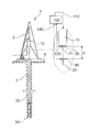
- FIG. 1 illustrates a basic design of a drilling device consisting of a drill string, sensors and a drive.
- FIG. 2 illustrates a control circuit of a dynamic system for calculating traveling vibrational waves.
- FIG. 1 illustrates a general design of a drilling device consisting of a drill string, sensors and a drive.
- the device for drilling 1 shown in FIG. 1 has a derrick 2 on which an actuator, the drill drive 10 is provided, with which a drill string 20 can be driven to turn a drill head 50 , also known as a bit, attached to the other end of the drill string 20 , which is situated in the drill hole 3 .
- the upper region is shown again in enlarged form in FIG. 1 .
- the drill drive 10 for example, an electric motor, drives the drill string 20 on which sensors are arranged, namely two sensors 30 , 40 here.
- These sensors 30 , 40 serve to determine measured variables which allow a determination of the angular state data, in particular the angular velocity of the drill string 20 at the corresponding sensor position.
- the sensors are arranged at a distance d from one another with a drill string region 21 in between.
- the sensors deliver their corresponding measurement signals over corresponding signal lines 130 , 140 to a control 100 .
- the measurement signals are evaluated to deliver a control signal via a control signal line 110 to the drill drive 10 on the basis of these signals.
- FIG. 2 illustrates a control circuit 100 of a dynamic system for calculation of traveling vibration waves.
- the control device 100 illustrated in FIG. 2 comprises a first input interface 131 for receiving first angular state data, in particular angular velocity data of a first sensor which is to be connected, a second input interface 141 for receiving second angular state data, in particular angular velocity data of a second sensor which is to be connected and an output interface 111 for output of a control value to a drive for a continuum and/or a drill string which is to be connected.
- the interfaces are linked to a control circuit 150 , which is designed to output a control value to the output interface 111 on the basis of the first angular state data, in particular angular velocity data, and a second angular state data, in particular angular velocity data, as well as the distance of the first sensor 30 from the second sensor 40 with the help of the wave equation and a model for torsional vibrations in a rod. Then the motor and/or actuator 10 can be controlled using this control value, for example, an angular velocity.
- the drilling tool 1 having a drill drive 10 , a drill string 20 and the control device for sensor-based control of torsional vibrations in a drill string and/or a slender continuum has the first sensor 30 and the second sensor 40 on the drill string 20 with a distance d, such that the drill drive 10 is linked to the output interface 111 of the control device 100 .
- the first sensor 30 and the second sensor 40 are arranged in an area of the drill string 20 which is situated above ground level 4 , so that these are accessible.
- the distance d should be at least as great as the quotient of the wave velocity of the vibrational wave on the drill string and the sampling rate. At a sampling rate of 1000 Hz and a wave velocity of 2000 m/s, the distance should thus be at least 2 meters.
- the drill string may be movable axially with respect to the first sensor 30 and the second sensor 40 , for example, by applying pulse generators running axially or other position markers to the drill string, extending axially.
- the sensors may be mounted very close to the actuator although the control method stabilizes the entire system.
- the control method described here both of the problems mentioned above can be solved. Measurements along the string are no longer needed, but at the same time the dynamics relevant for the control method can be calculated accurately from the two sensors mounted very close to the drive. Accordingly, the control method fits the current system behaviour exactly. In the case of the drill string, the loads that occur along the string are usually unknown and are highly variable in the course of the drilling operation, so it is of crucial importance that the controller adapts to the momentary system behaviour.
- two sensors are needed to measure the torsion angle and/or the angular velocity of the string directly on the drive as well as a small distance below the drive (e.g., 2 meters) (cf. detail in FIG. 1 ).
- the two measurement points are located above the ground area and are therefore readily accessible.
- the idea of the control method is based on the fact that the rate of propagation of torsional waves is infinite. In addition, the rate of propagation is independent of the frequency of the wave in question.
- the length of the structure in question be le, and the short section 0 ⁇ x ⁇ 1 of the structure shall be considered below and in addition: le>1. It is assumed that there are no externally acting torques within the section in question.
- the sensor spacing d is selected here to be 1. However, through appropriate scaling, all other spacings d are also possible.
- the measurements are assumed to be available continuously and free of noise. These measurements may be interpreted as time-dependent boundary conditions of the section in question.
- This system is simulated with the two measured angular velocities ⁇ 0 and ⁇ 1 as input in a real time computer.
- Real time is understood here to refer to boundary conditions in which a loop run-through of a control and/or regulating method is shorter than two successive sampling values of a sampling rate.
- the system is regulated not with respect to the speed zero but instead with respect to a fixed rotational speed, which is to be adapted by the operator of the plant to the prevailing situation. Accordingly, the unwanted torsional vibrations do not occur around the speed zero but instead around the desired rotational speed.
- the signal generated by the system described above is therefore filtered with the help of a high pass filter having a very low cutoff frequency so that the control system can be used for various rotational speeds and/or may also be used for switching between two rotational speeds.
- the system described in the theory part for continuously available sensor signals is necessarily discretized in implementation in the real system, i.e., the sensor data is available only at discrete instants in time. This may lead to very high frequency noise in the dynamic system described here, but this can easily be filtered out by using a suitable low-pass filter with a very high cutoff frequency.
- the frequency range relevant for the dynamics of the drill string remains unaffected by the filters and completely preserved.
- a functional embodiment may have a drill string, for example, which may be embodied by a drill string model having a length of 10 meters, for example.
- Angle sensors having an interpolated resolution of 25 bits and/or a physical resolution of 12 bits may be used as the sensors.
- the control may be implemented in software on a PC using a Quad-Core processor and Lab View RealTime.
- the present invention may also be used with other drive geometries in which torsional vibrations are to be expected in addition to being used in deep-hole drilling technology.
Landscapes
- Life Sciences & Earth Sciences (AREA)
- Engineering & Computer Science (AREA)
- Geology (AREA)
- Mining & Mineral Resources (AREA)
- Physics & Mathematics (AREA)
- Environmental & Geological Engineering (AREA)
- Fluid Mechanics (AREA)
- General Life Sciences & Earth Sciences (AREA)
- Geochemistry & Mineralogy (AREA)
- Earth Drilling (AREA)
- Percussive Tools And Related Accessories (AREA)
Abstract
Description
(δ^2φ(x,t))/(δt)^2=c^2(δ^2φ(x,t))/(δx)^2. (1)
The general solution of the wave equation is
φ(x,t)=f(x−ct)+g(x+ct), (2)
where φ(x, t) is the torsion angle as a function of the length coordinate x, parameter c is the wave propagation velocity in the material. It holds that c^2=G/p, where G is the shear modulus and ρ is the density of the material.
cτ=1 and/or τ=1/c (3)
i.e., τ corresponds to the propagation time of the wave between the two measurement points. Starting from the general solution and by definition of velocity waves
(kann das auch im deutschen Text noch berücksichtigt werden?)(x+ct) (inserting the general solution into the time-dependent boundary conditions):
Ω0(t)=α(−ct)+β(+ct), (4)
Ω1(t)=α(1−ct)+β(1+ct). (5)
α(1−ct)+α(−c(t−τ)), (6)
β(c(t−τ))=β(1+c(t−2τ)). (7)
Equation (4) with equation (7) yields:
Ω0(t−τ)=α(−c(t−τ))+β(1+c(t−2τ)). (8)
This in turn yields
α(−c(t−τ))=Ω0(t−τ)−β(1+c(t−2τ)). (9)
Ω1(t)=α(1−ct)+β(1+ct)=α(−c(t−τ))+β(1+ct). (10)
By inserting equation (9) in (10), this finally yields
Ω1(t)=Ω0(t−τ)−β(1+c(t−2τ))+β(1+ct). (11)
This shows that β(1+ct) can be calculated as a function of the two measured values Ω0 and Ω1 as well as its state in the past by 2τ:
β(1+ct)=Ω1(t)−Ω0(t−τ)+β(1+c(t−2τ)). (12)
If the initial values are known, e.g., because the system is started from a resting position, φ(x, 0)=0 and Ω(x, 0)=0, this yields
α(x=0,t=0)=0, (13)
α(x=1,t=0)=0, (14)
β(x=0,t=0)=0, (15)
β(x=1,t=0)=0. (16)
α(x=0,t)=α0,
α(x=1,t)=α1,
β(x=0,t)=β0,
β(x=1,t)=β1.
- 1 Drilling device
- 2 Derrick
- 3 Drill hole
- 4 Ground level
- 10 Drill drive
- 20 Drill string
- 21 Drill string range
- 30 First sensor
- 40 Second sensor
- 50 Drill head, bit
- 100 Control
- 110 Trigger signal line
- 111 Output interface
- 130 First measurement signal line
- 131 First input interface
- 140 Second measurement signal line
- 141 Second input interface
- 150 Control circuit
- d Distance d
Claims (16)
Applications Claiming Priority (4)
| Application Number | Priority Date | Filing Date | Title |
|---|---|---|---|
| DE102010046849.5 | 2010-09-29 | ||
| DE102010046849 | 2010-09-29 | ||
| DE201010046849 DE102010046849B8 (en) | 2010-09-29 | 2010-09-29 | Sensor-based control of vibrations in slender continuums, especially torsional vibrations in deep drill strings |
| PCT/EP2011/066419 WO2012041745A1 (en) | 2010-09-29 | 2011-09-21 | Sensor-based control of vibrations in slender continua, specifically torsional vibrations in deep-hole drill strings |
Publications (2)
| Publication Number | Publication Date |
|---|---|
| US20130248248A1 US20130248248A1 (en) | 2013-09-26 |
| US9494027B2 true US9494027B2 (en) | 2016-11-15 |
Family
ID=44719902
Family Applications (1)
| Application Number | Title | Priority Date | Filing Date |
|---|---|---|---|
| US13/876,835 Expired - Fee Related US9494027B2 (en) | 2010-09-29 | 2011-09-21 | Sensor-based control of vibrations in slender continua, specifically torsional vibrations in deep-hole drill strings |
Country Status (11)
| Country | Link |
|---|---|
| US (1) | US9494027B2 (en) |
| EP (1) | EP2622176B1 (en) |
| CN (1) | CN103154433B (en) |
| AU (1) | AU2011310735A1 (en) |
| BR (1) | BR112013007055A2 (en) |
| CA (1) | CA2812462A1 (en) |
| DE (1) | DE102010046849B8 (en) |
| DK (1) | DK2622176T3 (en) |
| EA (1) | EA027233B1 (en) |
| NO (1) | NO2622176T3 (en) |
| WO (1) | WO2012041745A1 (en) |
Families Citing this family (17)
| Publication number | Priority date | Publication date | Assignee | Title |
|---|---|---|---|---|
| DE102010046849B8 (en) | 2010-09-29 | 2012-08-02 | Tutech Innovation Gmbh | Sensor-based control of vibrations in slender continuums, especially torsional vibrations in deep drill strings |
| EP2783070A2 (en) * | 2011-11-25 | 2014-10-01 | Shell Internationale Research Maatschappij B.V. | Method and system for controlling vibrations in a drilling system |
| DE102013100965B4 (en) | 2013-01-30 | 2024-02-01 | Hasse & Wrede Gmbh | Method for actively isolating a drive train from torsional vibrations of a shaft of a machine, in particular a crankshaft of a reciprocating piston engine, and a corresponding arrangement for carrying out the method |
| DE102013100964B4 (en) | 2013-01-30 | 2021-09-02 | Hasse & Wrede Gmbh | Method for the active damping of torsional vibrations of a shaft of a machine, in particular a crankshaft of a reciprocating piston machine, |
| MX369745B (en) * | 2013-03-20 | 2019-11-20 | Schlumberger Technology Bv | CONTROL OF DRILLING SYSTEMS. |
| US9920612B2 (en) | 2013-03-21 | 2018-03-20 | Shell Oil Company | Method and system for damping vibrations in a tool string system |
| DE112013007342T5 (en) * | 2013-08-17 | 2016-05-04 | Halliburton Energy Services, Inc. | Method for optimizing drilling efficiency with reduced adhesion sliding effect |
| DE102014111404B4 (en) | 2014-08-11 | 2019-01-31 | Hasse & Wrede Gmbh | Method for actively damping vibrations of a shaft of an engine, in particular a crankshaft of a reciprocating engine, and a corresponding arrangement for carrying out the method |
| US10094209B2 (en) | 2014-11-26 | 2018-10-09 | Nabors Drilling Technologies Usa, Inc. | Drill pipe oscillation regime for slide drilling |
| DE102014119085A1 (en) | 2014-12-18 | 2016-06-23 | Hasse & Wrede Gmbh | Actuator assembly for applying a torque to a shaft, in particular a crankshaft of a reciprocating engine, and a corresponding method |
| US9784035B2 (en) | 2015-02-17 | 2017-10-10 | Nabors Drilling Technologies Usa, Inc. | Drill pipe oscillation regime and torque controller for slide drilling |
| CN105486347B (en) * | 2015-12-24 | 2017-07-14 | 安徽省城建设计研究总院有限公司 | For the equipment of drill site geological parameter and measurement, processing method |
| ITUA20164379A1 (en) * | 2016-06-15 | 2017-12-15 | Aurelio Pucci | GEOTHERMAL WELL TO COMMUNICATING VASES. |
| US11015425B2 (en) * | 2016-07-29 | 2021-05-25 | Halliburton Energy Services, Inc. | Mitigating vibrations in a drilling system |
| CN107229599B (en) * | 2017-06-21 | 2020-11-10 | 西南石油大学 | Method for monitoring torsional vibration of drill column |
| US20210062636A1 (en) * | 2017-09-05 | 2021-03-04 | Schlumberger Technology Corporation | Controlling drill string rotation |
| DE102019006214A1 (en) * | 2019-09-03 | 2021-03-04 | Erdwerk GmbH | Device and method for pressure protection of deep boreholes |
Citations (8)
| Publication number | Priority date | Publication date | Assignee | Title |
|---|---|---|---|---|
| US4965577A (en) | 1981-09-21 | 1990-10-23 | Hitachi, Ltd. | Semiconductor integrated circuit device having a wiring layout to avoid intersections between analog signal wiring layers and digital signal wiring layers |
| US4965774A (en) * | 1989-07-26 | 1990-10-23 | Atlantic Richfield Company | Method and system for vertical seismic profiling by measuring drilling vibrations |
| DE69102789T2 (en) | 1990-02-20 | 1995-01-19 | Shell Int Research | Method and system for controlling vibrations of a downhole device. |
| US5864058A (en) | 1994-09-23 | 1999-01-26 | Baroid Technology, Inc. | Detecting and reducing bit whirl |
| DE69926943T2 (en) | 1998-05-29 | 2006-07-13 | Eaton Electric N.V. | Circuit for testing a time-limited residual current device |
| US20090229882A1 (en) | 2008-03-17 | 2009-09-17 | Baker Hughes Incorporated | Distributed sensors-controller for active vibration damping from surface |
| WO2012041745A1 (en) | 2010-09-29 | 2012-04-05 | Technische Universität Hamburg-Harburg | Sensor-based control of vibrations in slender continua, specifically torsional vibrations in deep-hole drill strings |
| US8453764B2 (en) * | 2010-02-01 | 2013-06-04 | Aps Technology, Inc. | System and method for monitoring and controlling underground drilling |
Family Cites Families (3)
| Publication number | Priority date | Publication date | Assignee | Title |
|---|---|---|---|---|
| CA2209947C (en) * | 1995-01-12 | 1999-06-01 | Baker Hughes Incorporated | A measurement-while-drilling acoustic system employing multiple, segmented transmitters and receivers |
| US6327539B1 (en) * | 1998-09-09 | 2001-12-04 | Shell Oil Company | Method of determining drill string stiffness |
| US7219752B2 (en) * | 2003-11-07 | 2007-05-22 | Aps Technologies, Inc. | System and method for damping vibration in a drill string |
-
2010
- 2010-09-29 DE DE201010046849 patent/DE102010046849B8/en not_active Expired - Fee Related
-
2011
- 2011-09-21 EA EA201370047A patent/EA027233B1/en not_active IP Right Cessation
- 2011-09-21 BR BR112013007055A patent/BR112013007055A2/en not_active IP Right Cessation
- 2011-09-21 AU AU2011310735A patent/AU2011310735A1/en not_active Abandoned
- 2011-09-21 CN CN201180046419.5A patent/CN103154433B/en not_active Expired - Fee Related
- 2011-09-21 CA CA2812462A patent/CA2812462A1/en not_active Abandoned
- 2011-09-21 WO PCT/EP2011/066419 patent/WO2012041745A1/en not_active Ceased
- 2011-09-21 EP EP11761566.6A patent/EP2622176B1/en not_active Not-in-force
- 2011-09-21 US US13/876,835 patent/US9494027B2/en not_active Expired - Fee Related
- 2011-09-21 NO NO11761566A patent/NO2622176T3/no unknown
- 2011-09-21 DK DK11761566.6T patent/DK2622176T3/en active
Patent Citations (8)
| Publication number | Priority date | Publication date | Assignee | Title |
|---|---|---|---|---|
| US4965577A (en) | 1981-09-21 | 1990-10-23 | Hitachi, Ltd. | Semiconductor integrated circuit device having a wiring layout to avoid intersections between analog signal wiring layers and digital signal wiring layers |
| US4965774A (en) * | 1989-07-26 | 1990-10-23 | Atlantic Richfield Company | Method and system for vertical seismic profiling by measuring drilling vibrations |
| DE69102789T2 (en) | 1990-02-20 | 1995-01-19 | Shell Int Research | Method and system for controlling vibrations of a downhole device. |
| US5864058A (en) | 1994-09-23 | 1999-01-26 | Baroid Technology, Inc. | Detecting and reducing bit whirl |
| DE69926943T2 (en) | 1998-05-29 | 2006-07-13 | Eaton Electric N.V. | Circuit for testing a time-limited residual current device |
| US20090229882A1 (en) | 2008-03-17 | 2009-09-17 | Baker Hughes Incorporated | Distributed sensors-controller for active vibration damping from surface |
| US8453764B2 (en) * | 2010-02-01 | 2013-06-04 | Aps Technology, Inc. | System and method for monitoring and controlling underground drilling |
| WO2012041745A1 (en) | 2010-09-29 | 2012-04-05 | Technische Universität Hamburg-Harburg | Sensor-based control of vibrations in slender continua, specifically torsional vibrations in deep-hole drill strings |
Non-Patent Citations (13)
| Title |
|---|
| Berkooz, G., et al., "The Proper Orthogonal Decomposition, Wavelets and Modal Approaches to the Dynamics of Coherent Structures," Applied Scientific Research, vol. 53, pp. 321-338 (Apr. 19, 1994). |
| Dawson, R., et al., "Drill String Stick-Slip Oscillations," Proceedings of the 1987 Conference of the Society of Experimental Mechanics, 6 pp. (1987). |
| Halsey, G. W., et al., "Toque Feedback Used to Cure Slip-Stick Motion," Spe Annual Technical Conference and Exhibition, Houston, Texas, 6 pp. (Oct. 2-5, 1988). |
| International Search Report and Written Opinion issued by the European Patent Office as International Searching Authority for International Application No. PCT/EP2011/066419 dated Jan. 19, 2012 (8 pages). |
| Jansen, J. D. and van den Steen, L., "Active damping of self-excited torsional vibrations in oil well drillstrings," Journal of Sound and Vibration, vol. 179, No. 4, pp. 647-668 (Jan. 26, 1995). |
| Karkoub, M., et al., "Robust 4-synthesis controllers for suppressing stick-slip induced vibrations in oil well drill strings," Multibody Syst. Dyn., vol. 23, pp. 191-207 (2010). |
| Kreuzer, E. and Kust, O., "Analysis of long torsional strings by proper orthogonal decomposition," Archives of Applied Mechanics, vol. 67, No. 1, pp. 68-80 (Dec. 1996). |
| Kreuzer, E. and Steidl, M., "A Wave-Based Approach to Adaptively Control Self-Excited Vibrations in Drill-Strings," Proc. Appl. Math. Mech., vol. 10, pp. 509-510 (May 28, 2010). |
| Kreuzer, E., et al., "Control of Torsional Vibrations in Drill-Strings via Decomposition of Traveling Waves," Archive of Applied Mechanics, 18 pp. (2011). |
| O'Connor, William J., "Control of flexible mechanical systems: wave-based techniques," American Control Conference, ACC '07, IEEE, pp. 4192-4202 (Jul. 11-13, 2007). |
| Serrarens, a. F. A., et al., "Hop Control for Suppressing Stick-Slip in Oil Well Drillstrings," IEEE Control Systems Magazine, vol. 18, pp. 19-30 (1998). |
| Struck, H., et al., "Modellierung, Simulation and aktive Dampfung selbsterregter Schwingungen eines gekrummten Torsionsstranges," Ph. D. Thesis, Technische Universitat Hamburg-Harburg, 163 pp. (2004). |
| Tucker, W. R. and Wang, C., "On the Effective Control of Torsional Vibrations in Drilling Systems," Journal of Sound and Vibration, vol. 224, No. 1, pp. 101-122 (Jul. 1, 1999). |
Also Published As
| Publication number | Publication date |
|---|---|
| US20130248248A1 (en) | 2013-09-26 |
| DE102010046849B4 (en) | 2012-05-03 |
| WO2012041745A1 (en) | 2012-04-05 |
| DE102010046849A1 (en) | 2012-03-29 |
| AU2011310735A1 (en) | 2013-04-11 |
| EA201370047A1 (en) | 2013-09-30 |
| DE102010046849B8 (en) | 2012-08-02 |
| EP2622176A1 (en) | 2013-08-07 |
| CA2812462A1 (en) | 2012-04-05 |
| CN103154433B (en) | 2017-06-06 |
| CN103154433A (en) | 2013-06-12 |
| BR112013007055A2 (en) | 2016-06-14 |
| EA027233B1 (en) | 2017-07-31 |
| NO2622176T3 (en) | 2018-04-07 |
| DK2622176T3 (en) | 2018-01-29 |
| EP2622176B1 (en) | 2017-11-08 |
Similar Documents
| Publication | Publication Date | Title |
|---|---|---|
| US9494027B2 (en) | Sensor-based control of vibrations in slender continua, specifically torsional vibrations in deep-hole drill strings | |
| Jansen et al. | Active damping of self-excited torsional vibrations in oil well drillstrings | |
| US9624762B2 (en) | System and method for reducing drillstring oscillations | |
| EP3464808B1 (en) | A method of and a device for estimating down hole speed and down hole torque of borehole drilling equipment while drilling, borehole equipment and a computer program product | |
| EP2549055B2 (en) | Method and apparatus for reducing stick-slip | |
| Saldivar et al. | Suppressing axial-torsional coupled vibrations in drillstrings | |
| US9410417B2 (en) | Drilling control system and method | |
| US11073009B2 (en) | Drilling energy calculation based on transient dynamics simulation and its application to drilling optimization | |
| Mendil et al. | Hybrid sliding PID controller for torsional vibrations mitigation in rotary drilling systems | |
| Shi et al. | Optimal design of drag reduction oscillators by considering drillstring fatigue and hydraulic loss in sliding drilling | |
| Shor et al. | Drillstring vibration observation, modeling and prevention in the oil and gas industry | |
| NO20150944A1 (en) | Alternating frequency time domain approach to calculate the forced response of drill strings. | |
| Liu et al. | Mitigation of stick-slip vibrations in drilling systems with tuned top boundary parameters | |
| Gulyayev et al. | Simulation of torsion relaxation auto-oscillations of drill string bit with viscous and Coulombic friction moment models | |
| Alkaragoolee et al. | Investigation into the effect of friction decay factor on the modelling and attenuation of stick-slip vibrations of oilwell drilling systems | |
| Zhao | Torsional vibration control in oilwell drilling | |
| Gulyaev et al. | Self-excitation of deep-well drill string torsional vibrations | |
| Ammari et al. | Reconstructed drill-bit motion for sonic drillstring dynamics | |
| RU2569659C1 (en) | Method of drilling control and system for its implementation | |
| Saldivar Márquez et al. | Field Observations and Empirical Drilling Control | |
| Athanasiou | Virtual sensor for stress monitoring in shafts using distributed-lumped model | |
| RU2569652C1 (en) | Method of drilling control and system for its implementation | |
| Tucker et al. | A simple cosserat model for the dynamics of drill-strings | |
| Kancharla et al. | Analysis of Drillstring Vibrations using Active Circuits | |
| Krumm et al. | Active Impedance Matching in Slender Continua via a Special PID Controller |
Legal Events
| Date | Code | Title | Description |
|---|---|---|---|
| AS | Assignment |
Owner name: TECHNISCHE UNIVERSITAT HAMBURG-HARBURG, GERMANY Free format text: ASSIGNMENT OF ASSIGNORS INTEREST;ASSIGNORS:STEIDL, MICHAEL;KREUZER, EDWIN;REEL/FRAME:039825/0499 Effective date: 20130527 Owner name: TUTECH INNOVATION GMBH, GERMANY Free format text: ASSIGNMENT OF ASSIGNORS INTEREST;ASSIGNORS:STEIDL, MICHAEL;KREUZER, EDWIN;REEL/FRAME:039825/0499 Effective date: 20130527 |
|
| STCF | Information on status: patent grant |
Free format text: PATENTED CASE |
|
| FEPP | Fee payment procedure |
Free format text: MAINTENANCE FEE REMINDER MAILED (ORIGINAL EVENT CODE: REM.); ENTITY STATUS OF PATENT OWNER: LARGE ENTITY |
|
| LAPS | Lapse for failure to pay maintenance fees |
Free format text: PATENT EXPIRED FOR FAILURE TO PAY MAINTENANCE FEES (ORIGINAL EVENT CODE: EXP.); ENTITY STATUS OF PATENT OWNER: LARGE ENTITY |
|
| STCH | Information on status: patent discontinuation |
Free format text: PATENT EXPIRED DUE TO NONPAYMENT OF MAINTENANCE FEES UNDER 37 CFR 1.362 |
|
| FP | Expired due to failure to pay maintenance fee |
Effective date: 20201115 |