US949255A - Safety-razor. - Google Patents
Safety-razor. Download PDFInfo
- Publication number
- US949255A US949255A US48498809A US1909484988A US949255A US 949255 A US949255 A US 949255A US 48498809 A US48498809 A US 48498809A US 1909484988 A US1909484988 A US 1909484988A US 949255 A US949255 A US 949255A
- Authority
- US
- United States
- Prior art keywords
- blade
- razor
- handle portion
- strips
- clamping members
- Prior art date
- Legal status (The legal status is an assumption and is not a legal conclusion. Google has not performed a legal analysis and makes no representation as to the accuracy of the status listed.)
- Expired - Lifetime
Links
- 210000003813 thumb Anatomy 0.000 description 3
- 238000010276 construction Methods 0.000 description 2
- 230000000994 depressogenic effect Effects 0.000 description 2
- KWVIBDAKHDJCNY-UHFFFAOYSA-N 20alpha-atisine Natural products C12CCC3(C(C4=C)O)CCC4CC3C11CCCC2(C)CN2CCOC21 KWVIBDAKHDJCNY-UHFFFAOYSA-N 0.000 description 1
- 230000000881 depressing effect Effects 0.000 description 1
- 230000004048 modification Effects 0.000 description 1
- 238000012986 modification Methods 0.000 description 1
Images
Classifications
-
- B—PERFORMING OPERATIONS; TRANSPORTING
- B26—HAND CUTTING TOOLS; CUTTING; SEVERING
- B26B—HAND-HELD CUTTING TOOLS NOT OTHERWISE PROVIDED FOR
- B26B21/00—Razors of the open or knife type; Safety razors or other shaving implements of the planing type; Hair-trimming devices involving a razor-blade; Equipment therefor
- B26B21/08—Razors of the open or knife type; Safety razors or other shaving implements of the planing type; Hair-trimming devices involving a razor-blade; Equipment therefor involving changeable blades
- B26B21/14—Safety razors with one or more blades arranged transversely to the handle
- B26B21/18—Safety razors with one or more blades arranged transversely to the handle involving blades with two cutting edges
Definitions
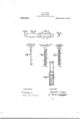
- FIG. 1 is a side view of]; the razoro't this invention. with portions shown incross-scction to show the interior ironstrneti'on thereof: Fi is an edge view l I i l of the razor of his invention, with portions shown in crossseetion to show the interior eonstmcti'on thcreot'fFigxil plan View 'of Fig. lFFig. 4 is'a plan View of the razor blade nsetl in the razor ofthis invention: g Fig. 5' is an'end view of the razor blade of 1' Fig.4; Fig.6 is a top end view of the handle 5 portions shown in Figs.
- Fig. 7 is an l edge elevation of thepair of clamping meml hers used for clampingthe razor blade in 3 place; and Fig. 9 is-a longitudinal cross-] sectional View of a portion of the handle of l the razor, with a portion shown in eleration, showing the interior eonstraction oft the handle portion.
- q f 1 Lilce eharactersrcfer to like parts in the several figure "o f in the drawings.
- loiswthe handle portion 5 ot'tho razor. which' is counter-bored from one end as at 3. and flt?lll( other end as at 3 to accommodate the washer l.
- the handle 5 :portion 1 is'also preferably turned down as i at 3 to give a neat appearance to the razor.
- llYashers -l and 6 are tightly placed in the handle portion 1 as shown in Fig. 8. andmay he further secured in place by any suitable. means. 'lat'h of the washers 4 and 6 i has a rectangular hole 7 therein as shown in higs. 6 and A pair oitlat strips 8 9. prefi erahly riveted together as atfi) 9. are carried within the handle pnrtiin l as shown in i il igs l and .2, these s'tnips S 8 extending i v I v '7 SAFETY-RAZOR.
- a coil spring 10 acting between washer 6 and cap nut 11, which nut is preferably screwed onto the threaded end portion 12 of the pair of strips 8 8 as shown.
- the spring lOnormally forces the pair of s rips 8 8 down into the handle portion 1 as far as they will go.
- the upper ends of the strips 8 8 extend along the entire length of the razor blade 13 as shown at; 14 14-.
- a lug 15 which has an inner tapered surface 16 adapted to engage a tapered a surface 17 at the end of the razor blade 13,
- each of the portions 14 is provided a series of teeth 18 18 preferably as shown.
- the razor blade 13 is sharpened along each longitudinal edge 19 19 preferably as shown.
- the t eth 18 18 n. will be readily understood. 7
- Each of the. strips 8 is provided at its upper end with a tapered portion -20. which tapered portions 20 .20 cooperate with the hole 7 in washer 4. as shown in Fig. 2. whereby the coil spring in forcing the strips 8 R down into the handle portion 1, causes the sides of the hole 7 in washer 4 to engage the tapered portions .20 20 and thereby draw the portions 14 11 toward each other and thus cause the lugs 15 15 to .sub stantially clamp the tapered end portions 17 17 of the blade 13 to securely hold the i blade 13 in place.
- the tapered portions 20 20 may he made to taper as much as desired. but the'taper is preferably made so that depressing the nut or but.- too 11 into the handle portion 1 until the, outer end thereof is tlush with the end of the handle portion '1. forces the strips a 8 out of the opposite end of th handle portion until they are spread apart, due to their own springiness. sufticiently to allow the blade 13 T to he readily removed therefrom.
- the tapered portions '20 '20 must be made so that, they will normally cause the blade 13 to be clamped in place. but will release it upon the small movement of the nut or button 11.
- a razor of the character described having a blade, a handle portion a pair of spring clamping members extending into the handle portion and tending to spring apart, a coil spring carried within the handle ortion for drawing the said clamping mem )ers down into the handle portion whereby they are drawn together to clamp the said blade.
- a razor of the character described comprising a blade having cutting edges on opposite sides thereof, a pair ot -springy clamping members adapted to carry the said blade and having series of teeth thereon adjacent the said cutting edges of the blade, and alsc lugs thereon at the ends thereof having tapered engaging relation with the ends of the .said' blade, a handle portion within which the said clamping members are carried, a coil spring wlthin the said handle portion acting on the said clamping members to cause them to automatically clamp the said blade in place, and a button at the opposite end of the handle portion from the blade, adapted to be depressed into the end of the handle portion against the action of the coil spring whereby the clamping members are caused to release the said blade.
- Atspring clunipin strips extendi into the said handle portion through the ho es in the said washers and adapted to clamp the razor blade therebctween, a coil spring carried within the handle portion around the said clam in strips and acting thereon to automation y draw the said strips together to clamp the said blade in place, and a thumb piece at the opposite end of the handle portion from the blade, adapted to be depresscd against the action of the coil sprin whereby the clamping ends of the sai clamping strips are permitted to spring apart and thereby release the said blade.
- a razor of the chamclendcscribcd com-- prising a handle portion having an opening at one end thereof, arazor blade, a pair of springy clamping members extending through the said opening into the handle portion, the said clamping members having tapered portions thereon adapted to coiipcrate with the sides of the said opening, a coil spring carried byihe handle 't-ortion for causing the coiiperation of the sai clamping members with the sides of the said opening whereby the said clamping members may be drawn toward each other to clamp the said blade in lace, and a thumb piece carried by the handle portion for causing the cotiperalion of the said clamping members with the sides of the said opening whereby the said clamping members are permitted to spread apart to release-the said blade, substantially as described.
- a razor of the character described comprising a removable blade having a cutting anisin for the blade extending longitudinally through the handle portion and adapted to engage the blade nuir each end thereof so that both ofthe cutting edges are exposed for use, spring mechanism acting on the said clampin ,meclmnism to cause the latter to clamp t e blade in place, and mechanism adapted to be operated against the action of the spring mechanism whereby the said clamping mechanism is caused to release the blade.
- a razor of the character described comprising'a handle portion,-'a removable blade, :1 pair of clamping members extending longitudinally through the handle portion and adapted to engage the blade near each end thereof to clamp same in place, spring 1nech anism acting on the said clamping members 5 anism whereby the said clamping members are caused to release the blade.
Landscapes
- Life Sciences & Earth Sciences (AREA)
- Forests & Forestry (AREA)
- Engineering & Computer Science (AREA)
- Mechanical Engineering (AREA)
- Knives (AREA)
Description
APPLICATION FILED MAR 22. 1909.
Patented Feb. 15, 1910.
WITNESSES.
ANT/101V) F .BALS,
" Application filed Marat 22,
To all wnom it may concern:
'Be it known that I, ANTHONY F. Bans, a' citizen of the l nited States of America, residing at Chicago. in the county of Cook l and State of Illinois, have. invented a new andjus eful Safety-Razor. of which thefol- 5 lowingis a specification. reference being had to the'hccompanying drawings. illustrating same. I I 4 The principal objects of m invention are, to provide improved means for readily clamping and holding a razor blade in place. in a safety razor. and for readily releasing the blade as desired; and to'provide other f improvements in the'construetion of such a razor. 1
' Qther objects will be apparent from the i following specification. "in the drawings Figure 1 is a side view of]; the razoro't this invention. with portions shown incross-scction to show the interior ironstrneti'on thereof: Fi is an edge view l I i l of the razor of his invention, with portions shown in crossseetion to show the interior eonstmcti'on thcreot'fFigxil plan View 'of Fig. lFFig. 4 is'a plan View of the razor blade nsetl in the razor ofthis invention: g Fig. 5' is an'end view of the razor blade of 1' Fig.4; Fig.6 is a top end view of the handle 5 portions shown in Figs. 1 and-2: Fig. 7 is an l edge elevation of thepair of clamping meml hers used for clampingthe razor blade in 3 place; and Fig. 9 is-a longitudinal cross-] sectional View of a portion of the handle of l the razor, with a portion shown in eleration, showing the interior eonstraction oft the handle portion. q f 1 Lilce eharactersrcfer to like parts in the several figure "o f in the drawings. loiswthe handle portion 5 ot'tho razor. which' is counter-bored from one end as at 3. and flt?lll( other end as at 3 to accommodate the washer l. The handle 5 :portion 1 is'also preferably turned down as i at 3 to give a neat appearance to the razor.
llYashers -l and 6 are tightly placed in the handle portion 1 as shown in Fig. 8. andmay he further secured in place by any suitable. means. 'lat'h of the washers 4 and 6 i has a rectangular hole 7 therein as shown in higs. 6 and A pair oitlat strips 8 9. prefi erahly riveted together as atfi) 9. are carried within the handle pnrtiin l as shown in i il igs l and .2, these s'tnips S 8 extending i v I v '7 SAFETY-RAZOR.
Specification of Letters Patent.
AN THONY F. BALS, OF CHICAGO, ILLINOIS.
1909. Serial N0. 484.988.
through the holes 7 'Z in the washers i and 6. Around the strips 8 8 and inside of the handle portion 1. is placed a coil spring 10, acting between washer 6 and cap nut 11, which nut is preferably screwed onto the threaded end portion 12 of the pair of strips 8 8 as shown. The spring lOnormally forces the pair of s rips 8 8 down into the handle portion 1 as far as they will go. The upper ends of the strips 8 8 extend along the entire length of the razor blade 13 as shown at; 14 14-. At each end of each portion 14 is provided a lug 15 which has an inner tapered surface 16 adapted to engage a tapered a surface 17 at the end of the razor blade 13,
preferably as shown. to substantially hold the razor blade in place. Along the outer edge of each of the portions 14 is provided a series of teeth 18 18 preferably as shown. The razor blade 13 is sharpened along each longitudinal edge 19 19 preferably as shown. The t eth 18 18 n. will be readily understood. 7
serve as guards for the sharp edges 19 19, to keep the razor from cutting where it, is not desired to cut. Each of the. strips 8 is provided at its upper end with a tapered portion -20. which tapered portions 20 .20 cooperate with the hole 7 in washer 4. as shown in Fig. 2. whereby the coil spring in forcing the strips 8 R down into the handle portion 1, causes the sides of the hole 7 in washer 4 to engage the tapered portions .20 20 and thereby draw the portions 14 11 toward each other and thus cause the lugs 15 15 to .sub stantially clamp the tapered end portions 17 17 of the blade 13 to securely hold the i blade 13 in place.
It will be readily understood that the tapered portions 20 20 may he made to taper as much as desired. but the'taper is preferably made so that depressing the nut or but.- too 11 into the handle portion 1 until the, outer end thereof is tlush with the end of the handle portion '1. forces the strips a 8 out of the opposite end of th handle portion until they are spread apart, due to their own springiness. sufticiently to allow the blade 13 T to he readily removed therefrom. Thus the tapered portions '20 '20 must be made so that, they will normally cause the blade 13 to be clamped in place. but will release it upon the small movement of the nut or button 11. When it is desired to remove the blade 13, it is onl necessar} to depress the button 11 Patented 1 5.1...15, 1910f against the action of coil spring 10, whereupon the clamping ends of the portions 8 S are permitted to spread apart, by their own splin tension, and thereby release the blade "ii herenpon the elampin ends of the strips 8 8 are automatically trawn together and the blade 13 thereby automatically clamped -,in place. Thus it will be seen that this arrangeinent for clamping the blade 13in place and permitting same to be removed as desired, is exceedingly simple in both its construction and its operation. If it is desired to remove the strips 8 8 from the handle portion 1, this may be done by unscrewing the nut 11 whereupon the strips 8 8 and coil spring 10 may .be readily removed from the handle portion.
It will be seen that in the razor of this invention there is no portion on the outside face of the blade 13, to be removed or operated before the blade l3 caii be removed from the holder. This greatly facilitates the removal of the blade.
I do not wish to limit this'invention to all of the particular details of construction herein shown, as various modifications of same may he made without departing fromthe scope of the appended claims.
That I claim as my invention is:
1. A razor of the character described having a blade, a handle portion a pair of spring clamping members extending into the handle portion and tending to spring apart, a coil spring carried within the handle ortion for drawing the said clamping mem )ers down into the handle portion whereby they are drawn together to clamp the said blade.
therebetween, and a thumb piece adapted to be depressed against the said coil spring to force the said clamping members out of the handle portion and thereby cause them to spread apart to release the said blade.
2. A razor of the character described comprising a blade having cutting edges on opposite sides thereof, a pair ot -springy clamping members adapted to carry the said blade and having series of teeth thereon adjacent the said cutting edges of the blade, and alsc lugs thereon at the ends thereof having tapered engaging relation with the ends of the .said' blade, a handle portion within which the said clamping members are carried, a coil spring wlthin the said handle portion acting on the said clamping members to cause them to automatically clamp the said blade in place, and a button at the opposite end of the handle portion from the blade, adapted to be depressed into the end of the handle portion against the action of the coil spring whereby the clamping members are caused to release the said blade.
3. A razor of the character describedconiprising a handle ortion counter-bored at each end, a washer or each of the said connterbores, rigidly secured therein, eachof the said washers having a rectangular hole therethrou h a razor blade, :1 pair of substantially. atspring clunipin strips extendi into the said handle portion through the ho es in the said washers and adapted to clamp the razor blade therebctween, a coil spring carried within the handle portion around the said clam in strips and acting thereon to automation y draw the said strips together to clamp the said blade in place, and a thumb piece at the opposite end of the handle portion from the blade, adapted to be depresscd against the action of the coil sprin whereby the clamping ends of the sai clamping strips are permitted to spring apart and thereby release the said blade.
4. A razor of the chamclendcscribcd com-- prising a handle portion having an opening at one end thereof, arazor blade, a pair of springy clamping members extending through the said opening into the handle portion, the said clamping members having tapered portions thereon adapted to coiipcrate with the sides of the said opening, a coil spring carried byihe handle 't-ortion for causing the coiiperation of the sai clamping members with the sides of the said opening whereby the said clamping members may be drawn toward each other to clamp the said blade in lace, and a thumb piece carried by the handle portion for causing the cotiperalion of the said clamping members with the sides of the said opening whereby the said clamping members are permitted to spread apart to release-the said blade, substantially as described.
5; A razor of the character described comprising a removable blade having a cutting anisin for the blade extending longitudinally through the handle portion and adapted to engage the blade nuir each end thereof so that both ofthe cutting edges are exposed for use, spring mechanism acting on the said clampin ,meclmnism to cause the latter to clamp t e blade in place, and mechanism adapted to be operated against the action of the spring mechanism whereby the said clamping mechanism is caused to release the blade. Y
6. A razor of the character described comprising'a handle portion,-'a removable blade, :1 pair of clamping members extending longitudinally through the handle portion and adapted to engage the blade near each end thereof to clamp same in place, spring 1nech anism acting on the said clamping members 5 anism whereby the said clamping members are caused to release the blade.
As inventor of the foregoing I hereunto subscribe my name, this lflth dny 0f March,
ANTHON Y F. ALS.
\ViinesQes MICHAEL. J. STARR,
vFnnmzmcn R. PAnmm.
Priority Applications (1)
| Application Number | Priority Date | Filing Date | Title |
|---|---|---|---|
| US48498809A US949255A (en) | 1909-03-22 | 1909-03-22 | Safety-razor. |
Applications Claiming Priority (1)
| Application Number | Priority Date | Filing Date | Title |
|---|---|---|---|
| US48498809A US949255A (en) | 1909-03-22 | 1909-03-22 | Safety-razor. |
Publications (1)
| Publication Number | Publication Date |
|---|---|
| US949255A true US949255A (en) | 1910-02-15 |
Family
ID=3017669
Family Applications (1)
| Application Number | Title | Priority Date | Filing Date |
|---|---|---|---|
| US48498809A Expired - Lifetime US949255A (en) | 1909-03-22 | 1909-03-22 | Safety-razor. |
Country Status (1)
| Country | Link |
|---|---|
| US (1) | US949255A (en) |
Cited By (4)
| Publication number | Priority date | Publication date | Assignee | Title |
|---|---|---|---|---|
| US3311975A (en) * | 1963-07-31 | 1967-04-04 | Climar A G | Blade injector razor having flexible means connecting the handle to the razor head |
| US3374540A (en) * | 1964-06-24 | 1968-03-26 | Climar A G | Razor |
| US20100132204A1 (en) * | 2008-12-03 | 2010-06-03 | Threshold Capital, Inc. | Razor with independent suspension |
| US20220168913A1 (en) * | 2019-03-29 | 2022-06-02 | Edgewell Personal Care Brands, Llc | Safety razor and handle for a safety razor |
-
1909
- 1909-03-22 US US48498809A patent/US949255A/en not_active Expired - Lifetime
Cited By (5)
| Publication number | Priority date | Publication date | Assignee | Title |
|---|---|---|---|---|
| US3311975A (en) * | 1963-07-31 | 1967-04-04 | Climar A G | Blade injector razor having flexible means connecting the handle to the razor head |
| US3374540A (en) * | 1964-06-24 | 1968-03-26 | Climar A G | Razor |
| US20100132204A1 (en) * | 2008-12-03 | 2010-06-03 | Threshold Capital, Inc. | Razor with independent suspension |
| US8671577B2 (en) * | 2008-12-03 | 2014-03-18 | Thomas A. Brown | Razor with independent suspension |
| US20220168913A1 (en) * | 2019-03-29 | 2022-06-02 | Edgewell Personal Care Brands, Llc | Safety razor and handle for a safety razor |
Similar Documents
| Publication | Publication Date | Title |
|---|---|---|
| US1201317A (en) | Safety-razor. | |
| US2741028A (en) | Holders for safety razor blades | |
| US2658541A (en) | Hacksaw frame with spare blade storage chamber | |
| US1024348A (en) | Safety-razor. | |
| US1454055A (en) | Razor-blade holder | |
| US1274966A (en) | Paper-clipper. | |
| US934074A (en) | Safety-razor. | |
| US991147A (en) | Safety-razor. | |
| US1966425A (en) | Combined safety razor and sharpening device | |
| US2229666A (en) | Elastic blade holder | |
| US3374540A (en) | Razor | |
| US2069465A (en) | Safety razor | |
| US852750A (en) | Holder for razor-blades. | |
| US925278A (en) | Knife. | |
| US2350467A (en) | Razor and blade holder | |
| US1389387A (en) | Safety-razor-blade holder | |
| US1307554A (en) | Samuel kohh | |
| US526917A (en) | Shearing-clippers | |
| US1017166A (en) | Safety-razor. | |
| US2793431A (en) | Safety razor with pivoted cap | |
| US941566A (en) | Razor-blade clamp. | |
| US870826A (en) | Safety-razor. | |
| US1096541A (en) | Holder for safety-razor sets. | |
| US863889A (en) | Safety-razor. | |
| US892750A (en) | Razor. |