US9491887B2 - Server with dual-side bridge circuit boards and method for assembling the same - Google Patents
Server with dual-side bridge circuit boards and method for assembling the same Download PDFInfo
- Publication number
- US9491887B2 US9491887B2 US14/583,430 US201414583430A US9491887B2 US 9491887 B2 US9491887 B2 US 9491887B2 US 201414583430 A US201414583430 A US 201414583430A US 9491887 B2 US9491887 B2 US 9491887B2
- Authority
- US
- United States
- Prior art keywords
- bridge circuit
- circuit board
- connector
- supportive frame
- board
- Prior art date
- Legal status (The legal status is an assumption and is not a legal conclusion. Google has not performed a legal analysis and makes no representation as to the accuracy of the status listed.)
- Active, expires
Links
Images


Classifications
-
- H—ELECTRICITY
- H05—ELECTRIC TECHNIQUES NOT OTHERWISE PROVIDED FOR
- H05K—PRINTED CIRCUITS; CASINGS OR CONSTRUCTIONAL DETAILS OF ELECTRIC APPARATUS; MANUFACTURE OF ASSEMBLAGES OF ELECTRICAL COMPONENTS
- H05K7/00—Constructional details common to different types of electric apparatus
- H05K7/14—Mounting supporting structure in casing or on frame or rack
- H05K7/1438—Back panels or connecting means therefor; Terminals; Coding means to avoid wrong insertion
- H05K7/1439—Back panel mother boards
- H05K7/1445—Back panel mother boards with double-sided connections
-
- G—PHYSICS
- G06—COMPUTING OR CALCULATING; COUNTING
- G06F—ELECTRIC DIGITAL DATA PROCESSING
- G06F1/00—Details not covered by groups G06F3/00 - G06F13/00 and G06F21/00
- G06F1/16—Constructional details or arrangements
- G06F1/18—Packaging or power distribution
- G06F1/183—Internal mounting support structures, e.g. for supporting printed circuit boards
-
- H—ELECTRICITY
- H05—ELECTRIC TECHNIQUES NOT OTHERWISE PROVIDED FOR
- H05K—PRINTED CIRCUITS; CASINGS OR CONSTRUCTIONAL DETAILS OF ELECTRIC APPARATUS; MANUFACTURE OF ASSEMBLAGES OF ELECTRICAL COMPONENTS
- H05K7/00—Constructional details common to different types of electric apparatus
- H05K7/14—Mounting supporting structure in casing or on frame or rack
- H05K7/1485—Servers; Data center rooms, e.g. 19-inch computer racks
- H05K7/1488—Cabinets therefor, e.g. chassis or racks or mechanical interfaces between blades and support structures
- H05K7/1492—Cabinets therefor, e.g. chassis or racks or mechanical interfaces between blades and support structures having electrical distribution arrangements, e.g. power supply or data communications
-
- G—PHYSICS
- G06—COMPUTING OR CALCULATING; COUNTING
- G06F—ELECTRIC DIGITAL DATA PROCESSING
- G06F1/00—Details not covered by groups G06F3/00 - G06F13/00 and G06F21/00
- G06F1/16—Constructional details or arrangements
- G06F1/18—Packaging or power distribution
-
- G—PHYSICS
- G06—COMPUTING OR CALCULATING; COUNTING
- G06F—ELECTRIC DIGITAL DATA PROCESSING
- G06F1/00—Details not covered by groups G06F3/00 - G06F13/00 and G06F21/00
- G06F1/16—Constructional details or arrangements
- G06F1/18—Packaging or power distribution
- G06F1/183—Internal mounting support structures, e.g. for supporting printed circuit boards
- G06F1/185—Mounting of expansion boards
-
- H—ELECTRICITY
- H05—ELECTRIC TECHNIQUES NOT OTHERWISE PROVIDED FOR
- H05K—PRINTED CIRCUITS; CASINGS OR CONSTRUCTIONAL DETAILS OF ELECTRIC APPARATUS; MANUFACTURE OF ASSEMBLAGES OF ELECTRICAL COMPONENTS
- H05K7/00—Constructional details common to different types of electric apparatus
- H05K7/14—Mounting supporting structure in casing or on frame or rack
- H05K7/1438—Back panels or connecting means therefor; Terminals; Coding means to avoid wrong insertion
-
- H—ELECTRICITY
- H05—ELECTRIC TECHNIQUES NOT OTHERWISE PROVIDED FOR
- H05K—PRINTED CIRCUITS; CASINGS OR CONSTRUCTIONAL DETAILS OF ELECTRIC APPARATUS; MANUFACTURE OF ASSEMBLAGES OF ELECTRICAL COMPONENTS
- H05K7/00—Constructional details common to different types of electric apparatus
- H05K7/14—Mounting supporting structure in casing or on frame or rack
- H05K7/1485—Servers; Data center rooms, e.g. 19-inch computer racks
- H05K7/1488—Cabinets therefor, e.g. chassis or racks or mechanical interfaces between blades and support structures
- H05K7/1489—Cabinets therefor, e.g. chassis or racks or mechanical interfaces between blades and support structures characterized by the mounting of blades therein, e.g. brackets, rails, trays
Definitions
- the invention relates to a server and a method for assembling the server, and more particularly to the server and the corresponding assembling method that integrate a first bridge circuit board and a second bridge circuit board into the server structure.
- a transfer board is usually applied to integrate a connecting backplane and other electronic components.
- the connecting backplane is used to receiving a plurality of hard discs, and thus shall have a huge capacity of data transmission.
- the connecting backplane is usually connected directly with the transfer board. Obviously, such a connection pattern can't provide sufficient capacity to meet the transmission load from the plurality of the hard discs.
- the connecting backplane is usually coupled directly to the transfer board.
- such a connection style is hard to meet the needs in huge data transmission.
- the server with dual-side bridge circuit board includes a transfer board, a connecting backplane, a first bridge circuit board and a second bridge circuit board.
- the transfer board has a first top surface and a first bottom surface opposing to the first top surface.
- One end of the first top surface has at least one first connector
- another end of the first bottom surface has at least one second connector.
- the connecting backplane has a second top surface and a second bottom surface opposing to the second top surface.
- the second top surface has at least one third connector located correspondingly to the at least one first connector
- the second bottom surface has at least one fourth connector located in correspondingly to the at least one second connector.
- the first bridge circuit board is inserted between the at least one first connector and the at least one third connector so as to electrically couple the transfer board and the connecting backplane.
- the second bridge circuit board is inserted between the at least one second connector and the at least one fourth connector so as to electrically couple the transfer board and the connecting backplane.
- a bandwidth for the communication between the transfer board and the connecting backplane can be extended by the combination of the first bridge circuit board and the second bridge circuit board.
- the transfer board further includes a supportive frame fixed at the first bridge circuit board.
- the first bridge circuit board and the supportive frame are integrated as a unique a piece before this combination of the first bridge circuit board and the supportive frame is inserted to couple the at least one first connector.
- the supportive frame further includes two opposing lateral slippery grooves for sliding and guiding the first bridge circuit board in between thereof so as to be fixed inside the supportive frame.
- the supportive frame further includes at least one first fixation pillar fixed at the first bridge circuit board.
- the supportive frame further includes at least one hook protrusion for constraining the first bridge circuit board inside the supportive frame.
- supportive frame further includes at least one observation hole for serving an observation purpose of checking an engagement state of the first bridge circuit board and the at least one first connector of the transfer board under the supportive frame.
- the supportive frame further includes at least one second fixation pillar fixed at the first bottom surface.
- the method for assembling a server with dual-side bridge circuit boards includes a step (a) of sending a first bridge circuit board into a supportive frame by sliding along two lateral slippery grooves of the supportive frame, and having at least one first fixation pillar of the supportive frame to fix the first bridge circuit board in the supportive frame, a step (b) of inserting a combination of the first bridge circuit board and the supportive frame to engage at least one first connector on a first top surface of a transfer board, a step (c) of having the supportive frame to be fixed by at least one second fixation pillar applied from a first bottom surface of the transfer board so as to fix the supportive frame and the first bridge circuit board on the transfer board, a step (d) of inserting a second bridge circuit board to engage at least one second connector on the first bottom surface, a step (e) of fixing the second bridge circuit board and the transfer board on a base casing, and a step (f) of engaging at least one third connector and at least one fourth connector of a connecting backplane respectively with the
- the first bridge circuit board in the step (a), while the first bridge circuit board slides into the supportive frame along the two lateral slippery grooves, the first bridge circuit board is to contact and thus be constrained by at least one hook protrusion of the supportive frame.
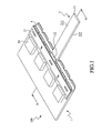
- FIG. 1 is a schematic perspective view of a preferred embodiment of the server with dual-side bridge circuit boards in accordance with the present invention
- FIG. 2 is another view of FIG. 1 , by exploding the supportive frame and removing the connecting backplane;
- FIG. 3 is another view of the supportive frame of FIG. 2 ;
- FIG. 4 is a schematic cross-sectional view of FIG. 1 along line A-A.
- the invention disclosed herein is directed to a server with dual-side bridge circuit boards and a method for assembling the same server.
- numerous details are set forth in order to provide a thorough understanding of the present invention. It will be appreciated by one skilled in the art that variations of these specific details are possible while still achieving the results of the present invention. In other instance, well-known components are not described in detail in order not to unnecessarily obscure the present invention.
- FIG. 1 is a schematic perspective view of a preferred embodiment of the server with dual-side bridge circuit boards in accordance with the present invention
- FIG. 2 is another view of FIG. 1 , by exploding the supportive frame and removing the connecting backplane
- FIG. 3 is another view of the supportive frame of FIG. 2
- FIG. 4 is a schematic cross-sectional view of FIG. 1 along line A-A.
- the server with dual-side bridge circuit boards 100 includes a transfer board 1 , a connecting backplane 2 , a first bridge circuit board 3 and a second bridge circuit board 4 .
- the transfer board 1 has a main circuit board 11 , seven first connectors 12 (one labeled in the figure), seven second connectors 13 (one labeled in the figure), five fixation holes 14 (one labeled in the figure), a supportive frame 15 and four heat dissipaters 16 (one labeled in the figure).
- the main circuit board 11 has a first top surface 111 and a first bottom surface 112 oppositely to the first top surface 111 .
- the seven first connectors 12 are discretely mounted on one side of the first top surface 111 .
- the second connectors 13 are discretely mounted on one side of the first bottom surface 112 .
- the five fixation holes 14 are evenly distributed on the transfer board 1 .
- the supportive frame 15 has two lateral slippery grooves 151 with base frames (one labeled in the figure), three observation holes 152 (one labeled in the figure), two hook protrusions 153 (one labeled in the figure), four first position pillars (not shown in the figure), three second position pillars (not shown in the figure) and five fixation holes 156 (one labeled in the figure).
- the two lateral slippery grooves 151 are oppositely and symmetrically located to respective lateral sides of the supportive frame 15 for providing and guiding the first bridge circuit board 3 to be inserted into the supportive frame 15 .
- the three observation holes 152 serve the same observation purpose for the user to check the engagement state of the first bridge circuit board 3 in between with the connectors 12 of the transfer board 1 under the supportive frame 15 .
- the two hook protrusions 153 is to buckle up the first bridge circuit board 3 so as to position and lock the first bridge circuit board 3 inside the supportive frame 15 , in which the first bridge circuit board 2 is sent through between the two lateral slippery grooves 151 of the supportive frame 15 .
- the first fixation pillar is fixed at the first bridge circuit board 3
- the second fixation pillar is fixed at the first bottom surface 112 by penetrating the main circuit board 11 .
- the five fixation holes 156 on the supportive frame 15 are located in correspondence with the other five fixation holes 14 on the main circuit board 11 , and are provided for the user to fix the supportive frame 15 onto the main circuit board 11 .
- the first bridge circuit board 3 is electrically coupled with the first connectors 12 , and is firmly fixed at the transfer board 1 by the supportive frame 15 .
- the four heat dissipaters 16 are discretely mounted on the main circuit board 11 .
- the supportive frame 15 is particularly constructed so as to alternatively arrange the four heat dissipaters 16 and the five fixation holes 156 .
- the connecting backplane 2 has a backplane body 21 , a third connector 22 and a fourth connector 23 .
- the backplane body 21 has a second top surface 211 and a second bottom surface 212 opposing to the second top surface 211 .
- the second top surface 211 has at least one (preferably, a pair of) third connector 22 to match the corresponding first connectors 12
- the second bottom surface 212 has at least one (preferably, a pair of) fourth connector 23 to match the corresponding second connectors 13 .
- the first bridge circuit board 3 is inserted between the first connectors 12 and the third connectors 22 , and thereby the first bridge circuit board 3 is electrically coupled to the transfer board 1 and the connecting backplane 2 .
- each opposing side of one end of the first bridge circuit 3 has seven connection ports 31 (one labeled in the figure) so as to engage electrically by inserting between the first connectors 12 and the third connectors 22 .
- the second bridge circuit board 4 is inserted between the second connectors 13 and the fourth connectors 23 , and thereby is electrically coupled to the transfer board 1 and the connecting backplane 2 .
- each opposing side of one end of the second bridge circuit 4 has seven connection ports 41 (one labeled in the figure) so as to engage electrically by inserting between the second connectors 13 and the fourth connectors 23 .
- the first bridge circuit board 3 is applied to electrically couple the first connectors 12 and the third connectors 22
- the second bridge circuit board 4 is applied to electrically couple the second connectors 13 and the fourth connectors 23 .
- communications between the transfer board 1 and the connecting backplane 2 can be performed, and the transmission bandwidth can be further extended through the integration of the first bridge circuit board 3 and the second bridge circuit board 4 .
- the present invention further includes the supportive frame 15 , so that the first bridge circuit board 3 can be firmly fixed on the transfer board 1 .
- the method for assembling the server with dual-side bridge circuit boards 100 in accordance with the present invention includes the following steps. Firstly, the first bridge circuit board 3 is sent into a space under the supportive frame 15 by sliding along the lateral slippery grooves 151 and being stopped at the hook protrusions 153 . The first fixation pillars of the supportive frame 15 are introduced to fix the first bridge circuit board 3 to the supportive frame 15 . Then, the combination of the first bridge circuit board 3 and the supportive frame 15 is inserted into the first connectors 12 on the first top surface 111 of the transfer board 1 .
- the supportive frame 15 is fixed by the second fixation pillars applied from the first bottom surface 112 so as to fix the combination of the supportive frame 15 and the first bridge circuit board 3 on the transfer board 1 .
- the second bridge circuit board 4 is inserted into the second connectors 13 on the first bottom surface 112 , and then the second bridge circuit board 4 and the transfer board 1 are fixed to a base casing (not shown in the figure).
- the third connectors 22 and the fourth connectors 23 of the connecting backplane 2 are inserted into the space between the first bridge circuit board 3 and the second bridge circuit board 4 so as to allow the first bridge circuit board 3 to be coupled between the third connectors 12 and the first connectors 22 and the second bridge circuit board 4 to be coupled between the fourth connectors 23 and the second connectors 13 .
Landscapes
- Engineering & Computer Science (AREA)
- Microelectronics & Electronic Packaging (AREA)
- General Engineering & Computer Science (AREA)
- Theoretical Computer Science (AREA)
- Computer Hardware Design (AREA)
- Power Engineering (AREA)
- Human Computer Interaction (AREA)
- Physics & Mathematics (AREA)
- General Physics & Mathematics (AREA)
- Mounting Of Printed Circuit Boards And The Like (AREA)
- Combinations Of Printed Boards (AREA)
Abstract
Description
Claims (9)
Applications Claiming Priority (3)
| Application Number | Priority Date | Filing Date | Title |
|---|---|---|---|
| CN201410640280.2A CN104391542B (en) | 2014-11-13 | 2014-11-13 | Server and its assemble method with two-sided bridging circuit board |
| CN201410640280 | 2014-11-13 | ||
| CN201410640280.2 | 2014-11-13 |
Publications (2)
| Publication Number | Publication Date |
|---|---|
| US20160143175A1 US20160143175A1 (en) | 2016-05-19 |
| US9491887B2 true US9491887B2 (en) | 2016-11-08 |
Family
ID=52609457
Family Applications (1)
| Application Number | Title | Priority Date | Filing Date |
|---|---|---|---|
| US14/583,430 Active 2035-06-24 US9491887B2 (en) | 2014-11-13 | 2014-12-26 | Server with dual-side bridge circuit boards and method for assembling the same |
Country Status (2)
| Country | Link |
|---|---|
| US (1) | US9491887B2 (en) |
| CN (1) | CN104391542B (en) |
Citations (6)
| Publication number | Priority date | Publication date | Assignee | Title |
|---|---|---|---|---|
| US20160205804A1 (en) * | 2015-01-12 | 2016-07-14 | Dell Products, L.P. | Server chassis with dual purpose bay for storage module or power supply module |
| US20160205812A1 (en) * | 2015-01-13 | 2016-07-14 | Tate Access Floors Leasing, Inc. | Air blocking panel assembly for a server or it rack |
| US20160211596A1 (en) * | 2013-08-02 | 2016-07-21 | Fujitsu Technology Solutions Intellectual Property Gmbh | Assembly for a computer system and angle plug |
| US20160234962A1 (en) * | 2015-02-10 | 2016-08-11 | Netapp Inc. | High Density Storage Device System |
| US20160242309A1 (en) * | 2015-02-16 | 2016-08-18 | Dell Products L.P. | Systems and methods for tool-less board to board coupling |
| US20160242311A1 (en) * | 2015-02-17 | 2016-08-18 | Wistron Corporation | Server apparatus and cable management mechanism thereof |
Family Cites Families (3)
| Publication number | Priority date | Publication date | Assignee | Title |
|---|---|---|---|---|
| CN201111022Y (en) * | 2007-08-23 | 2008-09-03 | 环旭电子(上海)有限公司 | Hard disc switching card |
| CN102214863A (en) * | 2010-04-07 | 2011-10-12 | 鸿富锦精密工业(深圳)有限公司 | Circuit board combination and connecting frame between boards thereof |
| CN102346514B (en) * | 2010-07-30 | 2013-06-12 | 英业达股份有限公司 | server blade module |
-
2014
- 2014-11-13 CN CN201410640280.2A patent/CN104391542B/en active Active
- 2014-12-26 US US14/583,430 patent/US9491887B2/en active Active
Patent Citations (6)
| Publication number | Priority date | Publication date | Assignee | Title |
|---|---|---|---|---|
| US20160211596A1 (en) * | 2013-08-02 | 2016-07-21 | Fujitsu Technology Solutions Intellectual Property Gmbh | Assembly for a computer system and angle plug |
| US20160205804A1 (en) * | 2015-01-12 | 2016-07-14 | Dell Products, L.P. | Server chassis with dual purpose bay for storage module or power supply module |
| US20160205812A1 (en) * | 2015-01-13 | 2016-07-14 | Tate Access Floors Leasing, Inc. | Air blocking panel assembly for a server or it rack |
| US20160234962A1 (en) * | 2015-02-10 | 2016-08-11 | Netapp Inc. | High Density Storage Device System |
| US20160242309A1 (en) * | 2015-02-16 | 2016-08-18 | Dell Products L.P. | Systems and methods for tool-less board to board coupling |
| US20160242311A1 (en) * | 2015-02-17 | 2016-08-18 | Wistron Corporation | Server apparatus and cable management mechanism thereof |
Also Published As
| Publication number | Publication date |
|---|---|
| CN104391542B (en) | 2018-04-06 |
| CN104391542A (en) | 2015-03-04 |
| US20160143175A1 (en) | 2016-05-19 |
Similar Documents
| Publication | Publication Date | Title |
|---|---|---|
| US9048569B2 (en) | Wire-to-board connector assembly and board-end connector thereof | |
| US9368883B2 (en) | Multi-cable connector | |
| US20130095676A1 (en) | Electrical connector assembly with compact configuration | |
| US9500814B2 (en) | Optical adapter module with managed connectivity | |
| US9606297B2 (en) | Transition connector for hybrid fiber optic cable | |
| US9837766B1 (en) | USB wireless dongle | |
| US9173304B2 (en) | Vertical blindmate scaling of identical system boards | |
| WO2018004819A3 (en) | Connector with structures for bi-lateral decoupling of a hardware interface | |
| US20150092325A1 (en) | Connector having waterproof function and electronic device using same | |
| WO2021139419A1 (en) | Panelized led display module and led box | |
| CN205882268U (en) | Electric connector shells assembly and electric connector | |
| US20190138475A1 (en) | Kvm extension device self-contained within a video connector | |
| US9016956B2 (en) | Optoelectronic transmission module | |
| US20130321241A1 (en) | Interface card and antenna fixture structure of communication module | |
| US9491887B2 (en) | Server with dual-side bridge circuit boards and method for assembling the same | |
| US10224673B2 (en) | Holder to constrain elastic members of a receptacle | |
| WO2006036918A3 (en) | Backplane with routing to reduce layer count | |
| JP2016146342A (en) | Electric connector assembly | |
| US20150044894A1 (en) | Usb/mini usb convertible connector | |
| US9112289B1 (en) | Stackable breadboard | |
| US20120071086A1 (en) | Electronic equipment with separable communications elements and electronic system having the same | |
| US9397452B1 (en) | Connecting device with jumper | |
| US20140206239A1 (en) | Backward compatible multichannel connector | |
| US20180019554A1 (en) | High density cable connector | |
| US20130016487A1 (en) | Memory adapter receiving device |
Legal Events
| Date | Code | Title | Description |
|---|---|---|---|
| AS | Assignment |
Owner name: INVENTEC (PUDONG) TECHNOLOGY CORPORATION, CHINA Free format text: ASSIGNMENT OF ASSIGNORS INTEREST;ASSIGNORS:WANG, JIA-BIN;ZHU, HUI;REEL/FRAME:034634/0569 Effective date: 20141204 Owner name: INVENTEC CORPORATION, TAIWAN Free format text: ASSIGNMENT OF ASSIGNORS INTEREST;ASSIGNORS:WANG, JIA-BIN;ZHU, HUI;REEL/FRAME:034634/0569 Effective date: 20141204 |
|
| AS | Assignment |
Owner name: INVENTEC CORPORATION, TAIWAN Free format text: CORRECTIVE ASSIGNMENT TO CORRECT THE SECOND ASSIGNEE'S CITY PREVIOUSLY RECORDED AT REEL: 034634 FRAME: 0569. ASSIGNOR(S) HEREBY CONFIRMS THE ASSIGNMENT;ASSIGNORS:WANG, JIA-BIN;ZHU, HUI;REEL/FRAME:040284/0059 Effective date: 20141204 Owner name: INVENTEC (PUDONG) TECHNOLOGY CORPORATION, CHINA Free format text: CORRECTIVE ASSIGNMENT TO CORRECT THE SECOND ASSIGNEE'S CITY PREVIOUSLY RECORDED AT REEL: 034634 FRAME: 0569. ASSIGNOR(S) HEREBY CONFIRMS THE ASSIGNMENT;ASSIGNORS:WANG, JIA-BIN;ZHU, HUI;REEL/FRAME:040284/0059 Effective date: 20141204 |
|
| STCF | Information on status: patent grant |
Free format text: PATENTED CASE |
|
| MAFP | Maintenance fee payment |
Free format text: PAYMENT OF MAINTENANCE FEE, 4TH YEAR, LARGE ENTITY (ORIGINAL EVENT CODE: M1551); ENTITY STATUS OF PATENT OWNER: LARGE ENTITY Year of fee payment: 4 |
|
| MAFP | Maintenance fee payment |
Free format text: PAYMENT OF MAINTENANCE FEE, 8TH YEAR, LARGE ENTITY (ORIGINAL EVENT CODE: M1552); ENTITY STATUS OF PATENT OWNER: LARGE ENTITY Year of fee payment: 8 |