US9490620B1 - Low permeability electrical feed-through - Google Patents
Low permeability electrical feed-through Download PDFInfo
- Publication number
- US9490620B1 US9490620B1 US14/858,994 US201514858994A US9490620B1 US 9490620 B1 US9490620 B1 US 9490620B1 US 201514858994 A US201514858994 A US 201514858994A US 9490620 B1 US9490620 B1 US 9490620B1
- Authority
- US
- United States
- Prior art keywords
- sealed
- diffusion
- region
- feed
- diffusion control
- Prior art date
- Legal status (The legal status is an assumption and is not a legal conclusion. Google has not performed a legal analysis and makes no representation as to the accuracy of the status listed.)
- Active
Links
Images


Classifications
-
- G—PHYSICS
- G11—INFORMATION STORAGE
- G11B—INFORMATION STORAGE BASED ON RELATIVE MOVEMENT BETWEEN RECORD CARRIER AND TRANSDUCER
- G11B5/00—Recording by magnetisation or demagnetisation of a record carrier; Reproducing by magnetic means; Record carriers therefor
- G11B5/84—Processes or apparatus specially adapted for manufacturing record carriers
-
- H—ELECTRICITY
- H02—GENERATION; CONVERSION OR DISTRIBUTION OF ELECTRIC POWER
- H02G—INSTALLATION OF ELECTRIC CABLES OR LINES, OR OF COMBINED OPTICAL AND ELECTRIC CABLES OR LINES
- H02G15/00—Cable fittings
- H02G15/013—Sealing means for cable inlets
-
- G—PHYSICS
- G06—COMPUTING OR CALCULATING; COUNTING
- G06F—ELECTRIC DIGITAL DATA PROCESSING
- G06F1/00—Details not covered by groups G06F3/00 - G06F13/00 and G06F21/00
- G06F1/16—Constructional details or arrangements
- G06F1/18—Packaging or power distribution
- G06F1/181—Enclosures
- G06F1/182—Enclosures with special features, e.g. for use in industrial environments; grounding or shielding against radio frequency interference [RFI] or electromagnetical interference [EMI]
-
- G—PHYSICS
- G11—INFORMATION STORAGE
- G11B—INFORMATION STORAGE BASED ON RELATIVE MOVEMENT BETWEEN RECORD CARRIER AND TRANSDUCER
- G11B25/00—Apparatus characterised by the shape of record carrier employed but not specific to the method of recording or reproducing, e.g. dictating apparatus; Combinations of such apparatus
- G11B25/04—Apparatus characterised by the shape of record carrier employed but not specific to the method of recording or reproducing, e.g. dictating apparatus; Combinations of such apparatus using flat record carriers, e.g. disc, card
- G11B25/043—Apparatus characterised by the shape of record carrier employed but not specific to the method of recording or reproducing, e.g. dictating apparatus; Combinations of such apparatus using flat record carriers, e.g. disc, card using rotating discs
-
- G—PHYSICS
- G11—INFORMATION STORAGE
- G11B—INFORMATION STORAGE BASED ON RELATIVE MOVEMENT BETWEEN RECORD CARRIER AND TRANSDUCER
- G11B33/00—Constructional parts, details or accessories not provided for in the other groups of this subclass
- G11B33/12—Disposition of constructional parts in the apparatus, e.g. of power supply, of modules
- G11B33/121—Disposition of constructional parts in the apparatus, e.g. of power supply, of modules the apparatus comprising a single recording/reproducing device
- G11B33/122—Arrangements for providing electrical connections, e.g. connectors, cables, switches
-
- G—PHYSICS
- G11—INFORMATION STORAGE
- G11B—INFORMATION STORAGE BASED ON RELATIVE MOVEMENT BETWEEN RECORD CARRIER AND TRANSDUCER
- G11B33/00—Constructional parts, details or accessories not provided for in the other groups of this subclass
- G11B33/14—Reducing influence of physical parameters, e.g. temperature change, moisture, dust
- G11B33/148—Reducing friction, adhesion, drag
-
- H—ELECTRICITY
- H01—ELECTRIC ELEMENTS
- H01R—ELECTRICALLY-CONDUCTIVE CONNECTIONS; STRUCTURAL ASSOCIATIONS OF A PLURALITY OF MUTUALLY-INSULATED ELECTRICAL CONNECTING ELEMENTS; COUPLING DEVICES; CURRENT COLLECTORS
- H01R13/00—Details of coupling devices of the kinds covered by groups H01R12/70 or H01R24/00 - H01R33/00
- H01R13/46—Bases; Cases
- H01R13/52—Dustproof, splashproof, drip-proof, waterproof, or flameproof cases
-
- H—ELECTRICITY
- H02—GENERATION; CONVERSION OR DISTRIBUTION OF ELECTRIC POWER
- H02G—INSTALLATION OF ELECTRIC CABLES OR LINES, OR OF COMBINED OPTICAL AND ELECTRIC CABLES OR LINES
- H02G1/00—Methods or apparatus specially adapted for installing, maintaining, repairing or dismantling electric cables or lines
- H02G1/06—Methods or apparatus specially adapted for installing, maintaining, repairing or dismantling electric cables or lines for laying cables, e.g. laying apparatus on vehicle
- H02G1/08—Methods or apparatus specially adapted for installing, maintaining, repairing or dismantling electric cables or lines for laying cables, e.g. laying apparatus on vehicle through tubing or conduit, e.g. rod or draw wire for pushing or pulling
-
- H—ELECTRICITY
- H05—ELECTRIC TECHNIQUES NOT OTHERWISE PROVIDED FOR
- H05K—PRINTED CIRCUITS; CASINGS OR CONSTRUCTIONAL DETAILS OF ELECTRIC APPARATUS; MANUFACTURE OF ASSEMBLAGES OF ELECTRICAL COMPONENTS
- H05K1/00—Printed circuits
- H05K1/02—Details
- H05K1/03—Use of materials for the substrate
- H05K1/0306—Inorganic insulating substrates, e.g. ceramic, glass
-
- H—ELECTRICITY
- H05—ELECTRIC TECHNIQUES NOT OTHERWISE PROVIDED FOR
- H05K—PRINTED CIRCUITS; CASINGS OR CONSTRUCTIONAL DETAILS OF ELECTRIC APPARATUS; MANUFACTURE OF ASSEMBLAGES OF ELECTRICAL COMPONENTS
- H05K1/00—Printed circuits
- H05K1/02—Details
- H05K1/11—Printed elements for providing electric connections to or between printed circuits
- H05K1/111—Pads for surface mounting, e.g. lay-out
- H05K1/112—Pads for surface mounting, e.g. lay-out directly combined with via connections
- H05K1/113—Via provided in pad; Pad over filled via
-
- H—ELECTRICITY
- H05—ELECTRIC TECHNIQUES NOT OTHERWISE PROVIDED FOR
- H05K—PRINTED CIRCUITS; CASINGS OR CONSTRUCTIONAL DETAILS OF ELECTRIC APPARATUS; MANUFACTURE OF ASSEMBLAGES OF ELECTRICAL COMPONENTS
- H05K1/00—Printed circuits
- H05K1/02—Details
- H05K1/11—Printed elements for providing electric connections to or between printed circuits
- H05K1/115—Via connections; Lands around holes or via connections
-
- H—ELECTRICITY
- H05—ELECTRIC TECHNIQUES NOT OTHERWISE PROVIDED FOR
- H05K—PRINTED CIRCUITS; CASINGS OR CONSTRUCTIONAL DETAILS OF ELECTRIC APPARATUS; MANUFACTURE OF ASSEMBLAGES OF ELECTRICAL COMPONENTS
- H05K3/00—Apparatus or processes for manufacturing printed circuits
- H05K3/40—Forming printed elements for providing electric connections to or between printed circuits
Definitions
- Embodiments of the invention may relate generally to hermetically sealed hard disk drives and more particularly to controlling gas leakage through an electrical feed-through.
- a hard-disk drive is a non-volatile storage device that is housed in a protective enclosure and stores digitally encoded data on one or more circular disk having magnetic surfaces.
- each magnetic-recording disk is rapidly rotated by a spindle system.
- Data is read from and written to a magnetic-recording disk using a read-write head that is positioned over a specific location of a disk by an actuator.
- a read-write head uses a magnetic field to read data from and write data to the surface of a magnetic-recording disk.
- a write head makes use of the electricity flowing through a coil, which produces a magnetic field. Electrical pulses are sent to the write head, with different patterns of positive and negative currents. The current n the coil of the write head induces a magnetic field across the gap between the head and the magnetic disk, which in turn magnetizes a small area on the recording medium.
- HDDs are being manufactured which are hermetically sealed with helium inside. Further, other gases that are lighter than air have been contemplated for use as a replacement for air in sealed HDDs.
- gases that are lighter than air have been contemplated for use as a replacement for air in sealed HDDs.
- operating in helium reduces the flutter of the disks and the suspension, allowing for disks to be placed closer together and increasing the areal density (a measure of the quantity of information bits that can be stored on a given area of disk surface) by enabling a smaller, narrower data track pitch.
- the lower shear forces and more efficient thermal conduction of helium also mean the HDD will run cooler and will emit less acoustic noise.
- the reliability of the HDDs is also increased due to low humidity, less sensitivity to altitude and external pressure variations, and the absence of corrosive gases or contaminants.
- Hermetically sealed internal volume e.g., a lighter-than-air gas filled, sealed HDD
- a hermetic electrical connector or electrical “feed-through”.
- One possible approach may involve the use of a low permeability but relatively expensive feed-through, such as glass-metal feed-through.
- Another approach may involve the use of a low-cost printed circuit board (PCB) feed-through, but these typically have a higher leak rate.
- PCB printed circuit board
- Embodiments of the invention are generally directed at a low permeability electrical feed-through and a hermetically-sealed hard disk drive (HDD) comprising such a low permeability feed-through.
- the low permeability electrical feed-through involves a laminated structure having a conductor layer sandwiched between adjacent insulator layers, which are sandwiched between adjacent diffusion control layers, where the laminated structure provides a high aspect ratio diffusion channel (i.e., relatively narrow and long) to inhibit the leakage of gas from within the sealed device to the external environment.
- the electrical feed-through may comprise lower and upper electrical connection pads that are positioned within different regions of the feed-through, but still electrically connected by way of a first via positioned in a sealed region, the conductor layer, and a second via positioned in an external environment region.
- Embodiments may include a via hole that is positioned entirely within either the sealed region or the external environment region of the electrical feed-through, preferably entirely within the external environment for lower leak rate purposes.
- a via hole that is positioned entirely within either the sealed region or the external environment region of the electrical feed-through, preferably entirely within the external environment for lower leak rate purposes.
- a particular capacitance or impedance
- a straight via-hole connection may be implemented only for the signal transmission lines that require low capacitance, where this via is positioned such that the high-frequency signal transmission lines are not routed between the diffusion control layers.
- Embodiments discussed in the Summary of Embodiments section are not meant to suggest, describe, or teach all the embodiments discussed herein.
- embodiments of the invention may contain additional or different features than those discussed in this section.
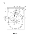
- FIG. 1 is a plan view illustrating a hard disk drive (HDD), according to an embodiment
- FIG. 2A is a perspective view illustrating an example electrical feed-through, according to an embodiment
- FIG. 2B is a cross-sectional side view illustrating a low permeability electrical feed-through, according to an embodiment
- FIG. 3 is an exploded perspective view illustrating a low permeability electrical feed-through, according to an embodiment
- FIG. 4 is a cross-sectional side view illustrating a low permeability electrical feed-through, according to an embodiment
- FIG. 5A is a top view illustrating the construction of a low permeability electrical feed-through, according to an embodiment
- FIG. 5B is a cross-sectional side view illustrating a low permeability electrical feed-through, according to an embodiment.
- FIG. 6 is a flow diagram illustrating a method of sealing an electrical feed-through, according to an embodiment.
- Embodiments may be used in the context of electrical feed-through for a hard disk drive (HDD).
- HDD hard disk drive
- FIG. 1 a plan view illustrating an HDD 100 is shown in FIG. 1 to illustrate an exemplary operating context.
- FIG. 1 illustrates the functional arrangement of components of the HDD 100 including a slider 110 b that includes a magnetic read-write head 110 a .
- slider 110 b and head 110 a may be referred to as a head slider.
- the HDD 100 includes at least one head gimbal assembly (HGA) 110 including the head slider, a lead suspension 110 c attached to the head slider typically via a flexure, and a load beam 110 d attached to the lead suspension 110 c .
- the HDD 100 also includes at least one magnetic-recording medium 120 rotatably mounted on a spindle 124 and a drive motor (not visible) attached to the spindle 124 for rotating the medium 120 .
- HGA head gimbal assembly
- the read-write head 110 a which may also be referred to as a transducer, includes a write element and a read element for respectively writing and reading information stored on the medium 120 of the HDD 100 .
- the medium 120 or a plurality of disk media may be affixed to the spindle 124 with a disk clamp 128 .
- the HDD 100 further includes an arm 132 attached to the HGA 110 , a carriage 134 , a voice-coil motor (VCM) that includes an armature 136 including a voice coil 140 attached to the carriage 134 and a stator 144 including a voice-coil magnet (not visible).
- the armature 136 of the VCM is attached to the carriage 134 and is configured to move the arm 132 and the HGA 110 , to access portions of the medium 120 , being mounted on a pivot-shaft 148 with an interposed pivot bearing assembly 152 .
- the carriage 134 is called an “E-block,” or comb, because the carriage is arranged to carry a ganged array of arms that gives it the appearance of a comb.
- An assembly comprising a head gimbal assembly (e.g., HGA 110 ) including a flexure to which the head slider is coupled, an actuator arm (e.g., arm 132 ) and/or load beam to which the flexure is coupled, and an actuator (e.g., the VCM) to which the actuator arm is coupled, may be collectively referred to as a head stack assembly (HSA).
- HSA head stack assembly
- An HSA may, however, include more or fewer components than those described.
- an HSA may refer to an assembly that further includes electrical interconnection components.
- an HSA is the assembly configured to move the head slider to access portions of the medium 120 for read and write operations.
- electrical signals comprising a write signal to and a read signal from the head 110 a
- a flexible interconnect cable 156 (“flex cable”).
- Interconnection between the flex cable 156 and the head 110 a may be provided by an arm-electronics (AE) module 160 , which may have an on-board pre-amplifier for the read signal, as well as other read-channel and write-channel electronic components.
- the AE module 160 may be attached to the carriage 134 as shown.
- the flex cable 156 is coupled to an electrical-connector block 164 , which provides electrical communication through electrical feed-throughs provided by an HDD housing 168 .
- the HDD housing 168 also referred to as a base, in conjunction with an HDD cover provides a sealed, protective enclosure for the information storage components of the HDD 100 .
- DSP digital-signal processor
- the spinning medium 120 commonly creates a cushion of air that acts as an air-bearing on which the air-bearing surface (ABS) of the slider 110 b rides so that the slider 110 b flies above the surface of the medium 120 without making contact with a thin magnetic-recording layer in which information is recorded.
- ABS air-bearing surface
- the spinning medium 120 creates a cushion of gas that acts as a gas or fluid bearing on which the slider 110 b rides.
- the electrical signal provided to the voice coil 140 of the VCM enables the head 110 a of the HGA 110 to access a track 176 on which information is recorded.
- the armature 136 of the VCM swings through an arc 180 , which enables the head 110 a of the HGA 110 to access various tracks on the medium 120 .
- Information is stored on the medium 120 in a plurality of radially nested tracks arranged in sectors on the medium 120 , such as sector 184 .
- each track is composed of a plurality of sectored track portions (or “track sector”), for example, sectored track portion 188 .
- Each sectored track portion 188 may be composed of recorded data and a header containing a servo-burst-signal pattern, for example, an ABCD-servo-burst-signal pattern, which is information that identifies the track 176 , and error correction code information.
- a servo-burst-signal pattern for example, an ABCD-servo-burst-signal pattern, which is information that identifies the track 176 , and error correction code information.
- the read element of the head 110 a of the HGA 110 reads the servo-burst-signal pattern which provides a position-error-signal (PES) to the servo electronics, which controls the electrical signal provided to the voice coil 140 of the VCM, enabling the head 110 a to follow the track 176 .
- PES position-error-signal
- the head 110 a Upon finding the track 176 and identifying a particular sectored track portion 188 , the head 110 a either reads data from the track 176 or writes data to the track 176 depending on instructions received by the disk controller from an external agent, for example, a microprocessor of a computer system.
- an external agent for example, a microprocessor of a computer system.
- An HDD's electronic architecture comprises numerous electronic components for performing their respective functions for operation of an HDD, such as a hard disk controller (“HDC”), an interface controller, an arm electronics module, a data channel, a motor driver, a servo processor, buffer memory, etc. Two or more of such components may be combined on a single integrated circuit board referred to as a “system on a chip” (“SOC”). Several, if not all, of such electronic components are typically arranged on a printed circuit board that is coupled to the bottom side of an HDD, such as to HDD housing 168 .
- HDC hard disk controller
- SOC system on a chip
- references herein to a hard disk drive may encompass a data storage device that is at times referred to as a “hybrid drive”.
- a hybrid drive refers generally to a storage device having functionality of both a traditional HDD (see, e.g., HDD 100 ) combined with solid-state storage device (SSD) using non-volatile memory, such as flash or other solid-state (e.g., integrated circuits) memory, which is electrically erasable and programmable.
- the solid-state portion of a hybrid drive may include its own corresponding controller functionality, which may be integrated into a single controller along with the HDD functionality.
- a hybrid drive may be architected and configured to operate and to utilize the solid-state portion in a number of ways, such as, for non-limiting examples, by using the solid-state memory as cache memory, for storing frequently-accessed data, for storing I/O intensive data, and the like. Further, a hybrid drive may be architected and configured essentially as two storage devices in a single enclosure, i.e., a traditional HDD and an SSD, with either one or multiple interfaces for host connection.
- hermetic will be understood to describe a sealing arrangement designed to have nominally no (or negligible) gaseous leakage or permeation paths. While terms such as “hermetic”, “negligible leakage”, “no leakage”, etc. may be used herein, note that such a system would often still have a certain amount of permeability and, therefore, not be absolutely leak free. Hence, the concept of a desired or target “leak rate” is described elsewhere herein. As discussed, electronic systems that require hermetically sealed internal volume (e.g., a lighter-than-air gas filled, sealed HDD) need a way of connecting electrical lines through the enclosure, and there remains a challenge regarding a low leakage rate versus the cost of a suitable electrical feed-through.
- hermetically sealed internal volume e.g., a lighter-than-air gas filled, sealed HDD
- FIG. 2A is a perspective view illustrating an example electrical feed-through, according to an embodiment.
- Electrical feed-through 200 (hereinafter, “feed-through 200 ”) may be referred to as a PCB (printed circuit board) based feed-through, fabricated using materials and processes generally associated with PCBs.
- PCB printed circuit board
- a PCB-based electrical feed-through such as feed-through 200 may comprise a laminate structure having at least one insulator layer 212 (e.g., FR-4 glass-reinforced epoxy, or plastic laminate) on which at least one diffusion control layer 210 is positioned thereover.
- the insulator layer(s) 212 is typically fabricated with a relatively gas-permeable material and, therefore, is too permeable to prohibit leakage of certain smaller molecule gases therethrough (e.g., helium, nitrogen, etc.).
- the diffusion control layer(s) 210 has a total channel perimeter length (CPL), the relevance of which is described elsewhere herein.
- feed-through 200 may comprise a plurality of electrical connections 226 (sometimes referred to generally as “electrical pads”), each electrically connected to a respective via 222 by way of a respective conductive layer 229 .
- the number of electrical connections 226 constituent to an electrical feed-through such as feed-through 200 may vary from implementation to implementation. Thus, the number of electrical connections 226 illustrated in FIG. 2A is for purposes of example only.
- feed-through 200 may comprise at least one via 224 having a via hole 225 , which are described in more detail elsewhere herein. Note also that a feed-through such as feed-through 200 need not be rectangular shaped, as the shape of feed-through 200 is illustrated as a rectangle for purposes of simplicity and example.
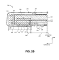
- FIG. 2B is a cross-sectional side view illustrating a low permeability electrical feed-through, according to an embodiment.
- the low permeability electrical feed-through 250 (hereinafter, “feed-through 250 ”) of FIG. 2B may be a cross-sectional view of the electrical feed-through 200 of FIG. 2A , but in the opposite direction (i.e., the perspective view of feed-through 200 of FIG. 2A is of the bottom surface(s) of the feed-through 250 of FIG. 2B ).
- FIG. 3 is an exploded perspective view illustrating a low permeability electrical feed-through, according to an embodiment, such as feed-through 250 of FIG. 2B .
- a low permeability electrical feed-through such a feed-through 250 may be for use with a sealed hard disk drive that includes a hermetically sealed gas-filled (e.g., a lighter-than-air type gas, such as helium, nitrogen, etc., for non-limiting examples) enclosure that has an opening extending through an HDD base 268 (e.g., similar to a hermetically-sealed version of housing 168 of FIG. 1 ).
- a hermetically sealed gas-filled e.g., a lighter-than-air type gas, such as helium, nitrogen, etc., for non-limiting examples
- an electrical connector may be disposed inside the enclosure and adjacent to the opening, and which can be electrically connected to a low permeability electrical feed-through such as feed-through 250 which spans the opening.
- an electrical connector may be electrically connected with an internal HDD flexible interconnect cable (e.g., flex cable 156 of FIG. 1 ), and with the feed-through 250 by way of electrical pads 226 .
- an internal HDD flexible interconnect cable e.g., flex cable 156 of FIG. 1
- feed-through 200 , 250 serve the purpose of facilitating electrical contact and connection between the outside and inside of the hermetically sealed cavity/enclosure.
- Feed-through 250 may be characterized as comprising three different regions: (1) a “sealed region” 202 that is exposed to the HDD internal gas (e.g., helium, nitrogen, etc.); (2) an “external environment region” 204 that is exposed to the external environment (e.g., ambient air); and (3) an “attachment region” 206 that is attached to a hermetically-sealed enclosure, such as base 268 , by way of an attachment 230 .
- the HDD internal gas e.g., helium, nitrogen, etc.
- an “external environment region” 204 that is exposed to the external environment (e.g., ambient air)
- an “attachment region” 206 that is attached to a hermetically-sealed enclosure, such as base 268 , by way of an attachment 230 .
- feed-through 250 is structurally configured such that negligible to no leakage of the HDD internal gas is permitted from inside an HDD to the external environment.
- feed-through 250 comprises multiple layers of low permeability material (for non-limiting examples, a metal such as copper, or glass) and insulator material (for a non-limiting example, FR-4), laminated in a particular manner as follows.
- Feed-through 250 comprises a first diffusion control layer 210 extending uninterrupted from attachment region 206 a distance along the external environment region 204 .
- the first diffusion control layer is a metal, such as copper for a non-limiting example.
- the first diffusion control layer is composed of a low permeability (low diffusion rate) dielectric, such as glass according to a related embodiment.
- the first diffusion control layer 210 overlaps with the attachment region 206 , in that the first diffusion control layer 210 is attached to the base 268 using, for non-limiting examples, an adhesive or solder (generally, attachment 230 ).
- Feed-through 250 further comprises a first insulator layer 212 on top of the first diffusion control layer 210 , where the first insulator layer 212 extends from a first via 222 positioned within the sealed region 202 to a second via 224 positioned within the external environment region 204 which is outside of the sealed region 202 .
- Feed-through 250 further comprises a conductor layer 214 on top of the first insulator layer 212 , whereby the conductor layer 214 electrically connects the first via 222 and the second via 224 .
- Conductor layer 214 is patterned to form electrical connection lines to carry signals back and forth between the first via 222 (and any electrical line, pin, post, etc. electrically and/or mechanically connected to the first via 222 ) and the second via 224 (and any electrical line, pin, post, etc. electrically and/or mechanically connected to the second via 224 ).
- conductor layer may carry signals from an internal flexible interconnect cable (e.g., flex cable 156 of FIG. 1 ) electrically connected to electrical pad 226 to an external HDD PCB (i.e., attached to the HDD) electrically connected to electrical pad 227 .
- Feed-through 250 further comprises a second insulator layer 216 on top of the conductor layer 214 , and a second diffusion control layer 218 on top of the second insulator layer 216 and extending uninterrupted across a majority of the length of the feed-through 250 .
- the second diffusion control layer is a metal, such as copper for a non-limiting example.
- the second diffusion control layer is composed of a low permeability (low diffusion rate) dielectric, such as glass according to a related embodiment.
- An additional optional insulator layer 220 may be present on top of the second diffusion control layer 218 , such as for mechanical stability.
- the first diffusion control layer 210 , the first insulator layer 212 , the second insulator layer 216 , and the second diffusion control layer 218 form a long and narrow diffusion path for any gas contained within an HDD enclosure such as base 268 , i.e., a diffusion path for the diffusion of gas from the sealed region 202 of feed-through 250 to the external environment region 204 of feed-through 250 , which is diffusion (i.e., leakage) that is desirable to control and inhibit.
- the conductor layer 214 is sandwiched within the other layers of the diffusion channel 240 , the conductor layer comprises a narrow metal line(s) and, therefore, does not function as a diffusion barrier to a practical degree.
- the diffusion channel 240 has a corresponding aspect ratio characterized by a ratio of the width of the diffusion channel 240 over the sum of the respective height of each of the first insulator layer 212 and the second insulator layer 216 , which are the more permeable material layers and hence the layers through which the gas primarily passes or leaks.
- This aspect ratio of the diffusion channel 240 thus dictates the amount of gas that may leak from the hermetically-sealed internal environment of an HDD through the feed-through 250 and into the external environment, whereby a higher aspect ratio results in a lower permeability feed-through.
- a long and narrow (high aspect ratio) diffusion channel inhibits leakage of gas from the internal sealed environment.
- the aspect ratio of the diffusion channel 240 is greater than the product of (a) a constant, K, representing the permeability of the gas; (b) the channel perimeter length, CPL, of the diffusion channel 240 ; and (c) a ratio of the pressure drop of the gas along the width (in transverse direction of FIG. 2B ) of the diffusion channel, dP, over the target leak rate, Q, or dP/Q.
- conductor layer is formed to carry signals from electrical pad 226 , which is positioned within the sealed region 202 of the feed-through 200 , 250 , to electrical pad 227 , which is positioned within the external environment region 204 of the feed-through 200 , 250 outside of the sealed region 202 .
- the first via 222 , the conductor layer 214 , the second via 224 , and another conductor layer 228 are configured to provide an electrical path between the electrical pad 226 within the sealed region 202 and the electrical pad 227 outside of the sealed region 202 (within the external environment region 204 ).
- the second via 224 comprises a via hole 225 and the via hole 225 is positioned entirely within a single region of the feed-through 200 , 250 , whether it be the sealed region 202 or the external environment region 204 , so that negligible or no leakage is likely to occur across the regions through the second via 224 and associated via hole 225 and the insulator around the via 224 .
- the via hole 225 is positioned entirely within the external environment region 204 , effectively ensuring that no leakage occurs from the sealed region 202 by way of the via 224 and associated via hole 225 .
- Capacitance is proportional to the surface area of two overlapping metal surfaces and inversely proportional to the distance between the two metal surfaces.
- a particular capacitance may be beneficial or even required. Consequently, the embodiment depicted in FIG. 2B may have too high capacitance, or too low impedance, for certain signal transmission lines. In such a scenario, a straight via-hole connection may be implemented only for the signal transmission lines that require low capacitance, according to an embodiment.
- there are typically only four (4) high-frequency signal transmission lines one pair for read, one pair for write, also referred to as receive/transmit lines), and all the other lines do not necessarily need accurate impedance matching.
- a high-frequency signal in the context of embodiments described herein is a signal having a frequency greater than several hundreds of megahertz, in order to achieve the data rate(s) specified in relevant interface protocols (e.g., SAS, SATA) for example.
- a high-frequency signal transmission line is in contrast with, for example, power lines, ground lines, control lines, and the like.
- FIG. 4 is a cross-sectional side view illustrating a low permeability electrical feed-through, according to an embodiment.
- a low permeability electrical feed-through such as feed-through 400 may be for use with a sealed hard disk drive that includes a hermetically sealed gas-filled (e.g., a lighter-than-air type gas, such as helium, nitrogen, etc., for non-limiting examples) enclosure that has an opening extending through an HDD base 268 .
- a hermetically sealed gas-filled e.g., a lighter-than-air type gas, such as helium, nitrogen, etc., for non-limiting examples
- feed-through 400 may be characterized as comprising three different regions: a “sealed region” that is exposed to the HDD internal gas (e.g., helium, nitrogen, etc.); an “external environment region” that is exposed to the external environment (e.g., ambient air); and an “attachment region” that is attached to a hermetically-sealed enclosure, such as base 268 , by way of attachment 430 .
- the HDD internal gas e.g., helium, nitrogen, etc.
- an “external environment region” that is exposed to the external environment (e.g., ambient air)
- an “attachment region” that is attached to a hermetically-sealed enclosure, such as base 268 , by way of attachment 430 .
- feed-through 400 is structurally configured to limit the amount of leakage of the HDD internal gas from inside an HDD to the external environment.
- feed-through 400 comprises multiple layers of low permeability material (for non-limiting examples, a metal such as copper, or glass) and insulator material (for a non-limiting example, FR-4), laminated in a particular manner.
- low permeability material for non-limiting examples, a metal such as copper, or glass
- insulator material for a non-limiting example, FR-4
- feed-through 400 may comprise a first diffusion control layer 410 extending uninterrupted from the attachment region a distance along the external environment region, a first insulator layer 412 on top of the first diffusion control layer 410 , a second insulator layer 416 on top of the first insulator layer 412 , and a second diffusion control layer 418 on top of the second insulator layer 416 and extending uninterrupted across a majority of the length of the feed-through 400 , layers whose composition and functionality may be similar to like-numbered elements described in reference to the feed-through 250 of FIG. 2B , a noteworthy feature of feed-through 400 is the via 450 (“third via”) electrically connecting a lower electrical pad 426 to an upper electrical pad 427 .
- the via 450 may be used to route the high-frequency signal transmission lines introduced elsewhere herein.
- an electrical feed-through (e.g., feed-through 400 and/or feed-through 250 of FIG. 2B ) comprises a third via positioned within the sealed region and electrically connecting a high-frequency signal transmission line between a lower electrical connection pad and an upper electrical connection pad, where the third via is positioned such that the high-frequency signal transmission line is not routed between the first and second diffusion control layers.
- third via 450 is positioned within the sealed region and electrically connects a high-frequency signal transmission line between a lower electrical connection pad 426 and an upper electrical connection pad 427 , where the third via 450 is positioned such that the high-frequency signal transmission line is not routed between the first and second diffusion control layers 410 , 418 .
- While use of straight via-hole connection such as via 450 may have a higher leak rate (i.e., more permeability) than the diffusion channel 240 ( FIG. 2B ) path, by reducing leakage from all other lines (non-high-frequency signal transmission lines) the total combined leak rate or permeability can be managed and controlled to the extent to meet a given target.
- the embodiments depicted and described in reference to FIG. 2B and in reference to FIG. 4 may be implemented separately or together. That is, embodiments include an implementation in which high-frequency signal transmission lines (such as the read pair and the write pair) are routed from the sealed region to the external environment region by way of a straight via-hole such as via 450 ( FIG.
- low diffusion rate (low permeability) dielectric material may be substituted for the foregoing uninterrupted diffusion control layers (e.g., first and second diffusion control layers 210 , 218 of FIGS. 2B and 3 ; 410 , 418 of FIG. 4 ), according to an embodiment.
- glass may be used for one or more of the diffusion control layers instead of metal, and coupled with the laminate structure using a low diffusion rate adhesive, such as epoxy, thereby managing the capacitance down to a suitable level for any high-frequency signal transmission lines that route between the diffusion control layers.
- FIG. 5A is a top view illustrating the construction of a low permeability electrical feed-through, according to an embodiment.
- Feed-through 504 comprises a laminate 500 having set of electrical pads 501 (such as feed-through 250 of FIGS. 2B and 3 and/or feed-through 400 of FIG. 4 ), over which a low diffusion rate (low permeability) dielectric material cap 502 (e.g., glass) is adhered.
- the dielectric material cap 502 comprises a cut-out area corresponding to the electrical pads such that the electrical pads 501 are not covered by the dielectric material and are therefore accessible for use.
- FIG. 5B is a cross-sectional side view illustrating a low permeability electrical feed-through, according to an embodiment.
- Feed-through 504 comprises a laminate 500 having set of upper electrical pads 501 and lower electrical pads 501 a (such as feed-through 250 of FIGS. 2B and 3 and/or feed-through 400 of FIG. 4 ), over both sides of which a low diffusion rate (low permeability) dielectric material cap 502 (e.g., glass) is adhered by an adhesive 510 , such as a low diffusion rate adhesive like epoxy.
- Each upper and lower dielectric material cap 502 comprises a cut-out area corresponding to the electrical pads such that the electrical pads 501 , 501 a are not covered by the dielectric material and are therefore accessible for use.
- FIG. 6 is a flow diagram illustrating a method of sealing an electrical feed-through, according to an embodiment, where the electrical feed-through is configured to interface between a hermetically-sealed environment and an external environment.
- the hermetically-sealed environment may be the internal cavity of a sealed hard disk drive having a lighter-than-air gas largely sealed therein.
- a first diffusion control layer is provided which extends uninterrupted from an attachment region of the electrical feed-through a distance along an external environment region of the electrical feed-through.
- first diffusion layer 210 FIG. 2B
- first diffusion layer 210 FIG. 2B
- first diffusion layer 210 FIG. 2B
- a first insulator layer is provided on top of the first diffusion control layer, whereby the first insulator layer extends from a first via positioned within a sealed region of the electrical feed-through to a second via positioned within the external environment region which is outside of the sealed region.
- the first insulator layer 212 ( FIG. 2B ) is provided on top of the first diffusion control layer 210 ( FIG. 2B ), whereby the first insulator layer 212 extends from a first via 222 ( FIG. 2B ) positioned within a sealed region 202 ( FIG. 2B ) of the electrical feed-through 250 ( FIG. 2B ) to a second via 224 ( FIG. 2B ) positioned within the external environment region 204 ( FIG. 2B ) which is outside of the sealed region 202 .
- a conductor layer is provided on top of the first insulator layer, whereby the conductor layer electrically connects the first via and the second via.
- the conductor layer 214 FIG. 2B
- the conductor layer 214 electrically connects the first via 222 ( FIG. 2B ) and the second via 224 ( FIG. 2B ).
- a second insulator layer is provided on top of the conductor layer.
- the second insulator layer 216 ( FIG. 2B ) is provided on top of the conductor layer 214 ( FIG. 2B ).
- a second diffusion control layer is provided on top of the second insulator layer, whereby the second diffusion control layer extends uninterrupted across a majority of the length of the electrical feed-through almost to the second via, and wherein the first diffusion control layer, the first insulator layer, the second insulator layer, and the second diffusion control layer form a high aspect ratio diffusion channel between the hermetically-sealed environment and the external environment.
- the second diffusion control layer 218 FIG. 2B
- the second diffusion control layer 218 is provided on top of the second insulator layer 216 ( FIG. 2B ), whereby the second diffusion control layer 218 extends uninterrupted across a majority of the length of the electrical feed-through 250 ( FIG. 2B ) almost to the second via 224 ( FIG.
- first diffusion control layer 210 FIG. 2B
- first insulator layer 212 FIG. 2B
- second insulator layer 216 FIG. 2B
- second diffusion control layer 218 form a high aspect ratio diffusion channel 240 ( FIG. 2B ) between the hermetically-sealed environment and the external environment.
- a diffusion channel may be characterized as having an aspect ratio characterized by a ratio of the width of the diffusion channel over the height of the diffusion channel.
- the diffusion channel 240 ( FIG. 2B ) may be characterized as having an aspect ratio characterized by a ratio of the width, W ( FIG. 2B ), of the diffusion channel 240 over the height, sum of T 1 and T 2 ( FIG. 2B ), of the diffusion channel 240 .
- the aspect ratio of the diffusion channel is greater than the product of (a) a constant representing the permeability of the gas; (b) the channel perimeter length of the diffusion channel; and (c) the ratio of the pressure drop of the gas along the width (in transverse direction of FIG. 2B ) of the diffusion channel over the target leak rate (see, e.g., equation (2)).
- the method depicted and described in reference to FIG. 6 may be extended to include the providing of any and/or all of the additional features depicted and described in reference to FIGS. 2A-5B .
- at least one pair of upper and lower electrical connection pads that are in different regions of the feed-through, which are electrically connected by way of the conductor layer and the first and second vias, may be provided.
- a third via within the sealed region of the feed-through may be provided to connect high-frequency signal transmission lines such that the lines are not routed between the diffusion control layers.
Landscapes
- Engineering & Computer Science (AREA)
- Microelectronics & Electronic Packaging (AREA)
- Physics & Mathematics (AREA)
- Theoretical Computer Science (AREA)
- Manufacturing & Machinery (AREA)
- Computer Hardware Design (AREA)
- Inorganic Chemistry (AREA)
- Electromagnetism (AREA)
- Ceramic Engineering (AREA)
- Power Engineering (AREA)
- Human Computer Interaction (AREA)
- General Engineering & Computer Science (AREA)
- General Physics & Mathematics (AREA)
- Chemical & Material Sciences (AREA)
- Installation Of Indoor Wiring (AREA)
- Structure Of Printed Boards (AREA)
- Supporting Of Heads In Record-Carrier Devices (AREA)
Abstract
Description
Q>K*T*CPL*dP/W; (1)
where,
K=a constant, representing the permeability of the gas,
T=the diffusion channel height (
CPL=the diffusion channel perimeter length (
W=the diffusion channel width (in transverse direction of
dP=the pressure drop of the gas across the diffusion channel (i.e., along the width, W, of the diffusion channel).
aspect ratio=W/T>K*CPL*dP/Q; (2)
where T=T1+T2, in the case of feed-through 250 of
Claims (22)
Priority Applications (3)
| Application Number | Priority Date | Filing Date | Title |
|---|---|---|---|
| US14/858,994 US9490620B1 (en) | 2015-09-18 | 2015-09-18 | Low permeability electrical feed-through |
| US15/228,983 US9736940B2 (en) | 2015-09-18 | 2016-08-04 | Low permeability electrical feed-through |
| CN201610833211.2A CN106971745B (en) | 2015-09-18 | 2016-09-19 | Low-permeability electricity feedthrough |
Applications Claiming Priority (1)
| Application Number | Priority Date | Filing Date | Title |
|---|---|---|---|
| US14/858,994 US9490620B1 (en) | 2015-09-18 | 2015-09-18 | Low permeability electrical feed-through |
Related Child Applications (1)
| Application Number | Title | Priority Date | Filing Date |
|---|---|---|---|
| US15/228,983 Continuation US9736940B2 (en) | 2015-09-18 | 2016-08-04 | Low permeability electrical feed-through |
Publications (1)
| Publication Number | Publication Date |
|---|---|
| US9490620B1 true US9490620B1 (en) | 2016-11-08 |
Family
ID=57211073
Family Applications (2)
| Application Number | Title | Priority Date | Filing Date |
|---|---|---|---|
| US14/858,994 Active US9490620B1 (en) | 2015-09-18 | 2015-09-18 | Low permeability electrical feed-through |
| US15/228,983 Active US9736940B2 (en) | 2015-09-18 | 2016-08-04 | Low permeability electrical feed-through |
Family Applications After (1)
| Application Number | Title | Priority Date | Filing Date |
|---|---|---|---|
| US15/228,983 Active US9736940B2 (en) | 2015-09-18 | 2016-08-04 | Low permeability electrical feed-through |
Country Status (2)
| Country | Link |
|---|---|
| US (2) | US9490620B1 (en) |
| CN (1) | CN106971745B (en) |
Cited By (12)
| Publication number | Priority date | Publication date | Assignee | Title |
|---|---|---|---|---|
| US20170169860A1 (en) * | 2015-12-09 | 2017-06-15 | HGST Netherlands B.V. | Hermetic sealing of hard disk drive using laminated film seal |
| US9704539B2 (en) | 2015-12-09 | 2017-07-11 | Western Digital Technologies, Inc. | Hermetic sealing of hard disk drive using laminated film seal |
| US9721620B2 (en) | 2015-12-09 | 2017-08-01 | Western Digital Technologies, Inc. | Hermetic sealing of hard disk drive using laminated film seal |
| CN107818193A (en) * | 2017-06-09 | 2018-03-20 | 中船黄埔文冲船舶有限公司 | A kind of ship piping system design verification method and system |
| US20190115051A1 (en) * | 2017-10-13 | 2019-04-18 | Kabushiki Kaisha Toshiba | Electronic device |
| US10395694B1 (en) * | 2017-08-09 | 2019-08-27 | Western Digital Technologies, Inc. | Low permeability electrical feed-through |
| US10424345B1 (en) | 2018-06-11 | 2019-09-24 | Western Digital Technologies, Inc. | Misalignment-tolerant flexible type electrical feed-through |
| US10594100B1 (en) | 2018-06-11 | 2020-03-17 | Western Digital Technologies, Inc. | Flexible type electrical feed-through connector assembly |
| US20200091641A1 (en) * | 2018-09-19 | 2020-03-19 | Kabushiki Kaisha Toshiba | Electronic device |
| US10629244B1 (en) | 2018-11-07 | 2020-04-21 | Western Digital Technologies, Inc. | Sealed electrical feed-through having reduced leak rate |
| US10706876B1 (en) * | 2019-06-13 | 2020-07-07 | Seagate Technology Llc | Wire assisted magnetic recording with an alternating current driving the wire |
| US11049515B1 (en) | 2020-05-08 | 2021-06-29 | Seagate Technology Llc | Dual wire assisted magnetic recording |
Families Citing this family (1)
| Publication number | Priority date | Publication date | Assignee | Title |
|---|---|---|---|---|
| JP6768730B2 (en) | 2018-03-30 | 2020-10-14 | 株式会社東芝 | Electronics |
Citations (9)
| Publication number | Priority date | Publication date | Assignee | Title |
|---|---|---|---|---|
| EP0844899B1 (en) | 1995-08-16 | 2003-07-30 | Alfred E. Mann Foundation For Scientific Research | Hermetically sealed electrical feedthrough for use with implantable electronic devices |
| US6989493B2 (en) | 2004-03-03 | 2006-01-24 | Seagate Technology Llc | Electrical feedthrough assembly for a sealed housing |
| US7019942B2 (en) | 2003-02-19 | 2006-03-28 | Seagate Technology Llc | Electrical feedthrough in a hermetically sealed data storage device |
| US7599147B2 (en) | 2005-08-05 | 2009-10-06 | Seagate Technology Llc | Electrical feedthrough assembly with elastic ring interface |
| US20110211279A1 (en) * | 2010-02-26 | 2011-09-01 | Western Digital Technologies, Inc. | Sealed laminated electrical connector for helium filled disk drive |
| US8035923B2 (en) | 2007-10-12 | 2011-10-11 | Hitachi Global Storage Technologies Netherlands B.V. | Data storage device |
| US8098454B2 (en) | 2007-12-26 | 2012-01-17 | Hitachi Global Storage Technologies Netherlands B.V. | Manufacturing method of hermetic connection terminal used in a disk drive device having hermetically sealed enclosure and disk drive device |
| US8593760B2 (en) | 2011-04-28 | 2013-11-26 | Entrotech, Inc. | Hard disk drives with electrical connectors comprising a flexible circuit extending through an opening in the base and related methods |
| US20150139770A1 (en) * | 2013-11-13 | 2015-05-21 | Brooks Automation, Inc. | Sealed robot drive |
Family Cites Families (5)
| Publication number | Priority date | Publication date | Assignee | Title |
|---|---|---|---|---|
| US6016000A (en) * | 1998-04-22 | 2000-01-18 | Cvc, Inc. | Ultra high-speed chip semiconductor integrated circuit interconnect structure and fabrication method using free-space dielectrics |
| US6523916B2 (en) * | 2000-12-22 | 2003-02-25 | Aurora Networks, Inc. | Chassis with repositionable plates |
| US7024936B2 (en) * | 2002-06-18 | 2006-04-11 | Corporation For National Research Initiatives | Micro-mechanical capacitive inductive sensor for wireless detection of relative or absolute pressure |
| US20050108875A1 (en) * | 2003-11-26 | 2005-05-26 | Mathieu Gaetan L. | Methods for making vertical electric feed through structures usable to form removable substrate tiles in a wafer test system |
| DE102009014334B4 (en) * | 2009-03-05 | 2011-01-27 | Schott Ag | Power connection device for containers |
-
2015
- 2015-09-18 US US14/858,994 patent/US9490620B1/en active Active
-
2016
- 2016-08-04 US US15/228,983 patent/US9736940B2/en active Active
- 2016-09-19 CN CN201610833211.2A patent/CN106971745B/en active Active
Patent Citations (10)
| Publication number | Priority date | Publication date | Assignee | Title |
|---|---|---|---|---|
| EP0844899B1 (en) | 1995-08-16 | 2003-07-30 | Alfred E. Mann Foundation For Scientific Research | Hermetically sealed electrical feedthrough for use with implantable electronic devices |
| US7019942B2 (en) | 2003-02-19 | 2006-03-28 | Seagate Technology Llc | Electrical feedthrough in a hermetically sealed data storage device |
| US6989493B2 (en) | 2004-03-03 | 2006-01-24 | Seagate Technology Llc | Electrical feedthrough assembly for a sealed housing |
| US7599147B2 (en) | 2005-08-05 | 2009-10-06 | Seagate Technology Llc | Electrical feedthrough assembly with elastic ring interface |
| US8035923B2 (en) | 2007-10-12 | 2011-10-11 | Hitachi Global Storage Technologies Netherlands B.V. | Data storage device |
| US8098454B2 (en) | 2007-12-26 | 2012-01-17 | Hitachi Global Storage Technologies Netherlands B.V. | Manufacturing method of hermetic connection terminal used in a disk drive device having hermetically sealed enclosure and disk drive device |
| US20110211279A1 (en) * | 2010-02-26 | 2011-09-01 | Western Digital Technologies, Inc. | Sealed laminated electrical connector for helium filled disk drive |
| US8194348B2 (en) | 2010-02-26 | 2012-06-05 | Western Digital Technologies, Inc. | Sealed laminated electrical connector for helium filled disk drive |
| US8593760B2 (en) | 2011-04-28 | 2013-11-26 | Entrotech, Inc. | Hard disk drives with electrical connectors comprising a flexible circuit extending through an opening in the base and related methods |
| US20150139770A1 (en) * | 2013-11-13 | 2015-05-21 | Brooks Automation, Inc. | Sealed robot drive |
Cited By (18)
| Publication number | Priority date | Publication date | Assignee | Title |
|---|---|---|---|---|
| US20170169860A1 (en) * | 2015-12-09 | 2017-06-15 | HGST Netherlands B.V. | Hermetic sealing of hard disk drive using laminated film seal |
| US9704539B2 (en) | 2015-12-09 | 2017-07-11 | Western Digital Technologies, Inc. | Hermetic sealing of hard disk drive using laminated film seal |
| US9721619B2 (en) * | 2015-12-09 | 2017-08-01 | Western Digital Technologies, Inc. | Hermetic sealing of hard disk drive using laminated film seal |
| US9721620B2 (en) | 2015-12-09 | 2017-08-01 | Western Digital Technologies, Inc. | Hermetic sealing of hard disk drive using laminated film seal |
| CN107818193A (en) * | 2017-06-09 | 2018-03-20 | 中船黄埔文冲船舶有限公司 | A kind of ship piping system design verification method and system |
| CN107818193B (en) * | 2017-06-09 | 2021-03-02 | 中船黄埔文冲船舶有限公司 | Verification method and system for ship piping design scheme |
| US10515668B2 (en) | 2017-08-09 | 2019-12-24 | Western Digital Technologies, Inc. | Low permeability electrical feed-through |
| US10395694B1 (en) * | 2017-08-09 | 2019-08-27 | Western Digital Technologies, Inc. | Low permeability electrical feed-through |
| US10580460B2 (en) * | 2017-10-13 | 2020-03-03 | Kabushiki Kaisha Toshiba | Electronic device having circuit board including third conductors insulated from first and second conductors |
| US20190115051A1 (en) * | 2017-10-13 | 2019-04-18 | Kabushiki Kaisha Toshiba | Electronic device |
| US10424345B1 (en) | 2018-06-11 | 2019-09-24 | Western Digital Technologies, Inc. | Misalignment-tolerant flexible type electrical feed-through |
| US10594100B1 (en) | 2018-06-11 | 2020-03-17 | Western Digital Technologies, Inc. | Flexible type electrical feed-through connector assembly |
| US20200091641A1 (en) * | 2018-09-19 | 2020-03-19 | Kabushiki Kaisha Toshiba | Electronic device |
| US11108178B2 (en) * | 2018-09-19 | 2021-08-31 | Kabushiki Kaisha Toshiba | Electronic device with housing storing electronic component |
| US10629244B1 (en) | 2018-11-07 | 2020-04-21 | Western Digital Technologies, Inc. | Sealed electrical feed-through having reduced leak rate |
| US10706876B1 (en) * | 2019-06-13 | 2020-07-07 | Seagate Technology Llc | Wire assisted magnetic recording with an alternating current driving the wire |
| US11049515B1 (en) | 2020-05-08 | 2021-06-29 | Seagate Technology Llc | Dual wire assisted magnetic recording |
| US11341990B1 (en) | 2020-05-08 | 2022-05-24 | Seagate Technology Llc | Dual wire assisted magnetic recording |
Also Published As
| Publication number | Publication date |
|---|---|
| CN106971745B (en) | 2019-06-28 |
| US9736940B2 (en) | 2017-08-15 |
| US20170086294A1 (en) | 2017-03-23 |
| CN106971745A (en) | 2017-07-21 |
Similar Documents
| Publication | Publication Date | Title |
|---|---|---|
| US9736940B2 (en) | Low permeability electrical feed-through | |
| US11264059B2 (en) | Sealed bulkhead electrical feed-through positioning control | |
| US9734874B1 (en) | Adhesive leak channel structure for hermetic sealing of a hard disk drive | |
| US9721619B2 (en) | Hermetic sealing of hard disk drive using laminated film seal | |
| US10594100B1 (en) | Flexible type electrical feed-through connector assembly | |
| US9721620B2 (en) | Hermetic sealing of hard disk drive using laminated film seal | |
| US9672870B1 (en) | Sealed bulkhead electrical feed-through X-Y positioning control | |
| US10424345B1 (en) | Misalignment-tolerant flexible type electrical feed-through | |
| US9570114B1 (en) | Laminated film-packed hard disk drive for hermetic sealing | |
| US20190378545A1 (en) | Flexible Type Electrical Feed-Through | |
| US9704539B2 (en) | Hermetic sealing of hard disk drive using laminated film seal | |
| US20160365105A1 (en) | Hard Disk Drive Actuator Pivot To Base Tower Clearance Spacer Mechanism | |
| US10164358B2 (en) | Electrical feed-through and connector configuration | |
| US11676628B1 (en) | Multiple-portion hard disk drive slider pad configuration | |
| US11430474B1 (en) | Hard disk drive suspension tail having narrowing tip | |
| US11069375B1 (en) | Suspension standoff arrangement for confining adhesive | |
| US20240040688A1 (en) | Flexible printed circuit finger layout for low crosstalk | |
| WO2018236435A1 (en) | REDUCING LEAKAGE RATE IN HERMETICALLY SEALED ADHESIVE DATA STORAGE DEVICES AND SYSTEMS | |
| US10515668B2 (en) | Low permeability electrical feed-through | |
| US11081130B1 (en) | Suspension standoff arrangement for confining adhesive | |
| US10629244B1 (en) | Sealed electrical feed-through having reduced leak rate |
Legal Events
| Date | Code | Title | Description |
|---|---|---|---|
| AS | Assignment |
Owner name: HGST NETHERLANDS B.V., NETHERLANDS Free format text: ASSIGNMENT OF ASSIGNORS INTEREST;ASSIGNORS:ALBRECHT, THOMAS R.;AMIN-SHAHIDI, DARYA;AYANOOR-VITIKKATE, VIPIN;AND OTHERS;SIGNING DATES FROM 20150903 TO 20150918;REEL/FRAME:036604/0628 |
|
| STCF | Information on status: patent grant |
Free format text: PATENTED CASE |
|
| AS | Assignment |
Owner name: WESTERN DIGITAL TECHNOLOGIES, INC., CALIFORNIA Free format text: ASSIGNMENT OF ASSIGNORS INTEREST;ASSIGNOR:HGST NETHERLANDS B.V.;REEL/FRAME:040831/0265 Effective date: 20160831 |
|
| AS | Assignment |
Owner name: WESTERN DIGITAL TECHNOLOGIES, INC., CALIFORNIA Free format text: CORRECTIVE ASSIGNMENT TO CORRECT THE INCORRECT SERIAL NO 15/025,946 PREVIOUSLY RECORDED AT REEL: 040831 FRAME: 0265. ASSIGNOR(S) HEREBY CONFIRMS THE ASSIGNMENT;ASSIGNOR:HGST NETHERLANDS B.V.;REEL/FRAME:043973/0762 Effective date: 20160831 |
|
| AS | Assignment |
Owner name: JPMORGAN CHASE BANK, N.A., AS AGENT, ILLINOIS Free format text: SECURITY INTEREST;ASSIGNOR:WESTERN DIGITAL TECHNOLOGIES, INC.;REEL/FRAME:052915/0566 Effective date: 20200113 |
|
| MAFP | Maintenance fee payment |
Free format text: PAYMENT OF MAINTENANCE FEE, 4TH YEAR, LARGE ENTITY (ORIGINAL EVENT CODE: M1551); ENTITY STATUS OF PATENT OWNER: LARGE ENTITY Year of fee payment: 4 |
|
| AS | Assignment |
Owner name: WESTERN DIGITAL TECHNOLOGIES, INC., CALIFORNIA Free format text: RELEASE OF SECURITY INTEREST AT REEL 052915 FRAME 0566;ASSIGNOR:JPMORGAN CHASE BANK, N.A.;REEL/FRAME:059127/0001 Effective date: 20220203 |
|
| AS | Assignment |
Owner name: JPMORGAN CHASE BANK, N.A., ILLINOIS Free format text: PATENT COLLATERAL AGREEMENT - A&R LOAN AGREEMENT;ASSIGNOR:WESTERN DIGITAL TECHNOLOGIES, INC.;REEL/FRAME:064715/0001 Effective date: 20230818 Owner name: JPMORGAN CHASE BANK, N.A., ILLINOIS Free format text: PATENT COLLATERAL AGREEMENT - DDTL LOAN AGREEMENT;ASSIGNOR:WESTERN DIGITAL TECHNOLOGIES, INC.;REEL/FRAME:067045/0156 Effective date: 20230818 |
|
| FEPP | Fee payment procedure |
Free format text: 7.5 YR SURCHARGE - LATE PMT W/IN 6 MO, LARGE ENTITY (ORIGINAL EVENT CODE: M1555); ENTITY STATUS OF PATENT OWNER: LARGE ENTITY |
|
| MAFP | Maintenance fee payment |
Free format text: PAYMENT OF MAINTENANCE FEE, 8TH YEAR, LARGE ENTITY (ORIGINAL EVENT CODE: M1552); ENTITY STATUS OF PATENT OWNER: LARGE ENTITY Year of fee payment: 8 |