US9490557B2 - Electronic card connector having improved terminals - Google Patents
Electronic card connector having improved terminals Download PDFInfo
- Publication number
- US9490557B2 US9490557B2 US14/688,171 US201514688171A US9490557B2 US 9490557 B2 US9490557 B2 US 9490557B2 US 201514688171 A US201514688171 A US 201514688171A US 9490557 B2 US9490557 B2 US 9490557B2
- Authority
- US
- United States
- Prior art keywords
- electronic card
- card connector
- tray
- contacting
- receiving cavity
- Prior art date
- Legal status (The legal status is an assumption and is not a legal conclusion. Google has not performed a legal analysis and makes no representation as to the accuracy of the status listed.)
- Active
Links
Images


Classifications
-
- H—ELECTRICITY
- H01—ELECTRIC ELEMENTS
- H01R—ELECTRICALLY-CONDUCTIVE CONNECTIONS; STRUCTURAL ASSOCIATIONS OF A PLURALITY OF MUTUALLY-INSULATED ELECTRICAL CONNECTING ELEMENTS; COUPLING DEVICES; CURRENT COLLECTORS
- H01R12/00—Structural associations of a plurality of mutually-insulated electrical connecting elements, specially adapted for printed circuits, e.g. printed circuit boards [PCB], flat or ribbon cables, or like generally planar structures, e.g. terminal strips, terminal blocks; Coupling devices specially adapted for printed circuits, flat or ribbon cables, or like generally planar structures; Terminals specially adapted for contact with, or insertion into, printed circuits, flat or ribbon cables, or like generally planar structures
- H01R12/50—Fixed connections
- H01R12/51—Fixed connections for rigid printed circuits or like structures
- H01R12/55—Fixed connections for rigid printed circuits or like structures characterised by the terminals
- H01R12/57—Fixed connections for rigid printed circuits or like structures characterised by the terminals surface mounting terminals
-
- G—PHYSICS
- G06—COMPUTING OR CALCULATING; COUNTING
- G06K—GRAPHICAL DATA READING; PRESENTATION OF DATA; RECORD CARRIERS; HANDLING RECORD CARRIERS
- G06K13/00—Conveying record carriers from one station to another, e.g. from stack to punching mechanism
- G06K13/02—Conveying record carriers from one station to another, e.g. from stack to punching mechanism the record carrier having longitudinal dimension comparable with transverse dimension, e.g. punched card
- G06K13/08—Feeding or discharging cards
-
- H—ELECTRICITY
- H01—ELECTRIC ELEMENTS
- H01R—ELECTRICALLY-CONDUCTIVE CONNECTIONS; STRUCTURAL ASSOCIATIONS OF A PLURALITY OF MUTUALLY-INSULATED ELECTRICAL CONNECTING ELEMENTS; COUPLING DEVICES; CURRENT COLLECTORS
- H01R12/00—Structural associations of a plurality of mutually-insulated electrical connecting elements, specially adapted for printed circuits, e.g. printed circuit boards [PCB], flat or ribbon cables, or like generally planar structures, e.g. terminal strips, terminal blocks; Coupling devices specially adapted for printed circuits, flat or ribbon cables, or like generally planar structures; Terminals specially adapted for contact with, or insertion into, printed circuits, flat or ribbon cables, or like generally planar structures
- H01R12/70—Coupling devices
- H01R12/71—Coupling devices for rigid printing circuits or like structures
-
- H—ELECTRICITY
- H01—ELECTRIC ELEMENTS
- H01R—ELECTRICALLY-CONDUCTIVE CONNECTIONS; STRUCTURAL ASSOCIATIONS OF A PLURALITY OF MUTUALLY-INSULATED ELECTRICAL CONNECTING ELEMENTS; COUPLING DEVICES; CURRENT COLLECTORS
- H01R13/00—Details of coupling devices of the kinds covered by groups H01R12/70 or H01R24/00 - H01R33/00
- H01R13/02—Contact members
- H01R13/22—Contacts for co-operating by abutting
- H01R13/24—Contacts for co-operating by abutting resilient; resiliently-mounted
- H01R13/245—Contacts for co-operating by abutting resilient; resiliently-mounted by stamped-out resilient contact arm
-
- H—ELECTRICITY
- H01—ELECTRIC ELEMENTS
- H01R—ELECTRICALLY-CONDUCTIVE CONNECTIONS; STRUCTURAL ASSOCIATIONS OF A PLURALITY OF MUTUALLY-INSULATED ELECTRICAL CONNECTING ELEMENTS; COUPLING DEVICES; CURRENT COLLECTORS
- H01R13/00—Details of coupling devices of the kinds covered by groups H01R12/70 or H01R24/00 - H01R33/00
- H01R13/40—Securing contact members in or to a base or case; Insulating of contact members
Definitions
- the present invention relates generally to an electronic card connector, and more particularly to an electronic card connector having improved terminals.
- Japan Patent No. JP2009295496 discloses a card connector including a housing, a number of terminals, and a metal shell.
- Each terminal includes a contacting portion, a rectangular frame portion, and an inclined supporting portion between the frame portion and the contacting portion.
- the supporting portion extends in a direction perpendicular to a card insertion direction.
- U.S. Pat. No. 7,967,640 discloses a card connector designed for working with a Subscriber Identity Module (SIM) card.
- SIM Subscriber Identity Module
- the rectangular SIM card is inserted into the card connector in such a manner that the shorter side of the card is parallel to the direction of card insertion.
- Contacts of the connector each include a contact portion, two elastic deformation portions, and a terminal portion.
- the two elastic deformation portions are coupled together so as to substantially form an isosceles triangle shape with a vertex angle ⁇ 1 at a vertex corresponding to the contact portion.
- the contact is arranged in an inverted V shape with respect to the card insertion direction.
- An electronic card connector having improved terminals is desired.
- an object of the present invention is to provide an electronic card connector having improved terminals to prevent damage of contacting portions thereof.
- An electronic card connector comprising: an insulative housing defining a receiving cavity and a base portion, the base portion having a plurality of terminal-receiving slots and an upper surface; a plurality of terminals each comprising an affixed portion retained in the base portion, an elastic portion extending upwardly into the receiving cavity, and a contacting portion formed at the elastic portion, each terminal defining a front point and a rear point respectively located on the elastic portion, the front point located in front of the contacting portion and the rear point located behind the contacting portion with respect to a card-inserting direction, a first part of the elastic portion located in a first plane, a second part of the elastic portion located in a second plane angled with respect to the first plane, the second part of the elastic portion having a connecting portion and a pair of frame portions connected with two free ends of the connecting portion, the elastic portion, the connecting portion, and the frame portions being resiliently deformable in an up-to-down direction; and a shielding shell attached to the insulative housing defining
- FIG. 1 is a perspective, assembled view of an electronic card connector
- FIG. 2 is a perspective, partly exploded view of the electrical card connector
- FIG. 3 is another perspective, partly exploded view of the electrical card connector
- FIG. 4 is a further perspective, exploded view of the electronic card connector
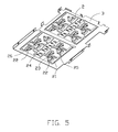
- FIG. 5 is a perspective, assembled view showing a number of terminals and a metal sheet embedded in an insulative housing
- FIG. 6 is a top view of the electrical card connector without a shielding shell, an ejector, and a tray;
- FIG. 7 is a cross-sectional view of the electrical card connector along line 7 - 7 in FIG. 6 .
- an electronic card connector 100 of the present invention includes an insulative housing 1 , a plurality of terminals 2 and a metal sheet 3 both affixed to the insulative housing 1 , a switch or detecting contact 4 located at an end of the insulative housing 1 , an ejector 5 located in the insulative housing 1 , and a shielding shell 6 attached to the insulative housing 1 and defining a receiving cavity 10 therebetween.
- the ejector 5 includes a pushing bar moveable along the front-to-back direction and a lever pivotally about a vertical axis.
- the electronic card connector 100 further has a tray 7 assembled in the receiving cavity 10 and capable of receiving two SIM cards at the same time.
- the electrical connector 100 defines a card-inserting direction, a front end and a rear end in FIG. 1 .
- the insulative housing 1 includes a base portion 11 , a side wall 12 located in one side of the base portion 11 , and a front wall 13 extending upwardly from the base portion 11 .
- the front wall 13 is formed with a depression 131 for receiving the switch 4 and a rotating pillar 132 shaped in a pillar for fixing the ejector 5 .
- the base portion 11 is formed with a number of terminal-receiving slots 113 located in two rows.
- the terminals 2 are located in two rows and received in the terminal-receiving slots 113 .
- Each terminal 2 includes an affixed portion 21 retained in the insulative housing 1 , an elastic portion extending upwardly into the receiving cavity 10 , a contacting portion 23 rising into the receiving cavity 10 , and a soldering portion 24 extending from the affixed portion 21 .
- the elastic potion includes a pair of elastic arms 22 extending upwardly to converge on the contacting portion 23 , a connecting portion 25 , and a pair of frame portions 26 connected with two end points of the connecting portion 25 .
- the elastic portion is resiliently deformable in an up-to-down direction.
- the connecting portion 25 plays an important role in stability so that an excessive drop of elastic deformation quantity of the two elastic arms 22 due to unequal pressure is reduced to avoid a plastic deformation of the two elastic arms 22 .
- the terminals 2 are divided in two teams numbering eight and configured in the insulative housing 1 in the card-inserting direction.
- the neighboring terminals 2 in the same team located along the card-inserting direction extend in a contrary direction to shorten the length of the electronic card connector 100 .
- the contacting portions 23 in a row along the card-inserting direction are arranged in a straight line.
- the frame portion 26 together with the connecting portion 25 and the affixed portion 21 is located in a first plane parallel to the base portion 11 in this embodiment.
- the two elastic arms 22 are located in a second plane forming a sharp angle with the first plane.
- the affixed portion 21 of each terminal 2 is embedded in the base portion 11 .
- the frame portions 26 and the connecting portion 25 of each terminal 2 are exposed to the terminal-receiving slot 113 and capable of elastic deformation along the up-to-down direction.
- the two frame portions 26 are parallel to each other and each frame portion 26 connects corresponding elastic arm 22 to corresponding affixed portion 21 . Referring to FIGS.
- the elastic arms 22 employ a cantilever beam arrangement to rise into the receiving cavity 10 .
- the base portion 11 defines an upper surface 110 higher than a plane where the affixed portion 21 , connecting portion 25 , and the frame portion 26 are located.
- the affixed portion 21 , the frame portion 26 , the connecting portion 25 , the elastic arm 22 , and the contacting portion 23 are located along a transverse direction perpendicular to the card-inserting direction and configured in this embodiment so that the terminals 2 is not easy to collapse or be broken when the tray 7 is movable.
- the elastic arm 22 can be configured as winding or curved shape.
- the two elastic arms 22 of each terminal 2 respectively define a rear point 2201 and a front point 2202 .
- the rear point 2201 is located at the back of the contacting portion 23 and the front point 2202 is located at the front of the contacting portion 23 .
- the connecting portion 25 in different embodiments is located beside the base portion 11 and connected with the affixed portion 21 or separated from the affixed portion 21 .
- the number of the connecting portion 23 is two, one is located beside the base portion 11 and connected with the affixed portion 21 , and the other is separated from the affixed portion 21 .
- the switch 4 includes a movable terminal 41 and an affixed terminal 42 retained in the front wall 13 and received in the depression 131 .
- the switch 4 stays closed when the tray 7 is absent, while the switch 4 stays separated when the tray 7 is assembled.
- the ejector 5 includes a lever 51 and a cam 52 configured as prior arts.
- the shielding shell 6 includes a main body 61 , a pair of side bodies 62 extending downwardly from the main body 61 , a locking portion 611 located on the main body 61 and a locking arm 621 located on the side body 62 and extending horizontally into the receiving cavity 10 .
- the locking portion 611 has a protrusion 6111 therein protruding to the receiving cavity 10 .
- the locking arm 621 has a projection 6211 therein protruding to the receiving cavity 10 and corresponding to the protrusion 6111 .
- the locking arm 621 is located under the locking portion 611 in the up-to-down direction, so that the projection 6211 is located under the protrusion 6211 in the up-to-down direction.
- the locking portion 611 and the locking arm 621 are both affixed beams to make the protrusion 6111 and the projection 6211 capable of elastic deformation in the up-to-down direction.
- the tray 7 is formed as a rectangle frame and includes a card-receiving room 70 , a panel portion 71 , an operating portion 72 connected with the panel portion 71 , and a partition 712 .
- the partition 712 separates the card-receiving room 70 to a first receiving part 701 and a second receiving part 702 to receive two SIM cards at the same time.
- the first receiving part 701 and the second receiving part 702 are located along the card-inserting direction and has a same dimension.
- the panel portion 71 has a pair of side portions 711 and a pair of notches 7111 located on the upper and bottom surface of the side portion 711 .
- the notches 7111 are engaged with the protrusion 6111 and the projection 6211 to lock the tray 7 in the receiving cavity 10 .
Landscapes
- Engineering & Computer Science (AREA)
- Physics & Mathematics (AREA)
- General Physics & Mathematics (AREA)
- Theoretical Computer Science (AREA)
- Coupling Device And Connection With Printed Circuit (AREA)
- Details Of Connecting Devices For Male And Female Coupling (AREA)
- Computer Networks & Wireless Communication (AREA)
- Signal Processing (AREA)
- Artificial Intelligence (AREA)
- Computer Vision & Pattern Recognition (AREA)
Abstract
Description
Claims (12)
Priority Applications (2)
| Application Number | Priority Date | Filing Date | Title |
|---|---|---|---|
| US15/150,405 US9760810B2 (en) | 2014-07-01 | 2016-05-09 | Electronic card connector assembly having improved terminals to avoid scuffing |
| US15/702,154 US10176410B2 (en) | 2014-07-01 | 2017-09-12 | Electronic card connector assembly having improved terminals to avoid scuffing |
Applications Claiming Priority (3)
| Application Number | Priority Date | Filing Date | Title |
|---|---|---|---|
| CN201410306722 | 2014-07-01 | ||
| CN201410306722 | 2014-07-01 | ||
| CN201410306722.X | 2014-07-01 |
Related Parent Applications (1)
| Application Number | Title | Priority Date | Filing Date |
|---|---|---|---|
| US15/150,405 Continuation US9760810B2 (en) | 2014-07-01 | 2016-05-09 | Electronic card connector assembly having improved terminals to avoid scuffing |
Related Child Applications (2)
| Application Number | Title | Priority Date | Filing Date |
|---|---|---|---|
| US15/150,405 Continuation-In-Part US9760810B2 (en) | 2014-07-01 | 2016-05-09 | Electronic card connector assembly having improved terminals to avoid scuffing |
| US15/702,154 Continuation-In-Part US10176410B2 (en) | 2014-07-01 | 2017-09-12 | Electronic card connector assembly having improved terminals to avoid scuffing |
Publications (2)
| Publication Number | Publication Date |
|---|---|
| US20160006173A1 US20160006173A1 (en) | 2016-01-07 |
| US9490557B2 true US9490557B2 (en) | 2016-11-08 |
Family
ID=52947355
Family Applications (1)
| Application Number | Title | Priority Date | Filing Date |
|---|---|---|---|
| US14/688,171 Active US9490557B2 (en) | 2014-07-01 | 2015-04-16 | Electronic card connector having improved terminals |
Country Status (5)
| Country | Link |
|---|---|
| US (1) | US9490557B2 (en) |
| JP (1) | JP6272262B2 (en) |
| KR (1) | KR20160003557A (en) |
| CN (3) | CN204464550U (en) |
| TW (1) | TWI586037B (en) |
Cited By (3)
| Publication number | Priority date | Publication date | Assignee | Title |
|---|---|---|---|---|
| US20160254606A1 (en) * | 2014-07-01 | 2016-09-01 | Foxconn Interconnect Technology Limited | Electronic card connector assembly having improved terminals to avoid scuffing |
| US9780469B2 (en) * | 2015-05-19 | 2017-10-03 | Molex, Llc | Card connector enabling the use of various types of cards |
| US11749944B2 (en) | 2020-04-09 | 2023-09-05 | Rosenberger Hochfrequenztechnik Gmbh & Co. Kg | Fastening screw, electrical plug connector and electrical plug connection |
Families Citing this family (20)
| Publication number | Priority date | Publication date | Assignee | Title |
|---|---|---|---|---|
| CN204464550U (en) * | 2014-07-01 | 2015-07-08 | 富士康(昆山)电脑接插件有限公司 | Card connector |
| KR101603141B1 (en) * | 2014-08-14 | 2016-03-14 | 몰렉스 엘엘씨 | Fixing apparatus of ejecting type card tray for electronic equipment |
| US9391382B1 (en) * | 2015-07-30 | 2016-07-12 | Cheng Uei Precision Industry Co., Ltd. | Card connector having a heat activated film welded between a shielding shell and a housing |
| CN106450844A (en) * | 2015-08-04 | 2017-02-22 | 富士康(昆山)电脑接插件有限公司 | Electronic card connector |
| CN105024194B (en) * | 2015-08-17 | 2018-05-29 | 广东欧珀移动通信有限公司 | Card seat structure and mobile terminal thereof |
| JP1553879S (en) * | 2015-11-03 | 2016-07-11 | ||
| JP1553611S (en) * | 2015-11-03 | 2016-07-11 | ||
| JP1552812S (en) * | 2015-11-03 | 2016-06-27 | ||
| JP1552813S (en) * | 2015-11-04 | 2016-06-27 | ||
| JP1552814S (en) * | 2015-11-04 | 2016-06-27 | ||
| JP1552815S (en) * | 2015-11-06 | 2016-06-27 | ||
| CN107404019B (en) * | 2016-05-19 | 2023-07-14 | 深圳市长盈精密技术股份有限公司 | Card connector |
| KR102348705B1 (en) | 2017-03-02 | 2022-01-10 | 삼성전자주식회사 | Device for preventing over-discharge and electronic device with the same |
| CN110326167B (en) * | 2017-04-19 | 2021-08-10 | Oppo广东移动通信有限公司 | Card trays, plug-in devices and terminals |
| CN111740251B (en) | 2018-10-15 | 2022-04-12 | 华为技术有限公司 | Card Connectors, Holders and Terminals |
| JP1680768S (en) * | 2020-05-14 | 2021-03-08 | ||
| TWI751592B (en) * | 2020-06-24 | 2022-01-01 | 維將科技股份有限公司 | Card connector |
| CN111987496B (en) * | 2020-09-10 | 2022-03-04 | 国网新疆电力有限公司和田供电公司 | Parallel groove clamp mounting tool and using method thereof |
| CN113161781B (en) * | 2021-03-30 | 2023-02-10 | 深圳市长盈精密技术股份有限公司 | Card holder connector |
| KR102770088B1 (en) | 2023-09-01 | 2025-02-21 | (주)우주일렉트로닉스 | Connector Apparatus with Deformation Prevention Structure of Switch Member |
Citations (6)
| Publication number | Priority date | Publication date | Assignee | Title |
|---|---|---|---|---|
| WO2002073819A2 (en) | 2001-03-12 | 2002-09-19 | Molex Incorporated | Sim card socket and manufacturing method therefor |
| JP2009295496A (en) | 2008-06-06 | 2009-12-17 | Yazaki Syscomplus Co Ltd | Card connector and connector terminal |
| CN101783451A (en) | 2009-01-09 | 2010-07-21 | 山一电机株式会社 | card connector |
| TWM466378U (en) | 2013-01-31 | 2013-11-21 | Singatron Entpr Co Ltd | SIM card socket connector |
| CN103579810A (en) | 2012-08-07 | 2014-02-12 | 莫列斯公司 | card connector |
| US20150050840A1 (en) | 2013-08-16 | 2015-02-19 | Tyco Electronics Japan G.K. | Card Connector and Connector |
Family Cites Families (16)
| Publication number | Priority date | Publication date | Assignee | Title |
|---|---|---|---|---|
| JP3534024B2 (en) * | 1999-11-08 | 2004-06-07 | 住友電装株式会社 | Card edge connector |
| TW490098U (en) * | 2001-04-13 | 2002-06-01 | Advanced Connectek Inc | Electric connector |
| TWM300382U (en) * | 2006-03-31 | 2006-11-01 | Suyin Corp | Connector for a SIM card |
| CN201207470Y (en) * | 2008-05-23 | 2009-03-11 | 实盈电子(东莞)有限公司 | Improved terminal of electronic card connector |
| EP2159884A1 (en) * | 2008-08-29 | 2010-03-03 | Tyco Electronics Nederland B.V. | Laminated low profile connector for chip cards |
| JP4623753B2 (en) * | 2008-12-03 | 2011-02-02 | Smk株式会社 | Memory card connector |
| JP2011165560A (en) * | 2010-02-12 | 2011-08-25 | Japan Aviation Electronics Industry Ltd | Card connector |
| CN201708318U (en) * | 2010-05-27 | 2011-01-12 | 美国莫列斯股份有限公司 | Sim card connector |
| JP5424003B2 (en) * | 2012-02-28 | 2014-02-26 | Smk株式会社 | Tray card connector |
| JP5382385B2 (en) * | 2012-03-28 | 2014-01-08 | Smk株式会社 | Card connector |
| CN202855990U (en) * | 2012-10-10 | 2013-04-03 | 深圳君泽电子有限公司 | Terminal of connector and battery connector with terminal |
| CN103280668B (en) * | 2013-05-02 | 2016-07-06 | 昆山嘉华电子有限公司 | Card connector |
| CN203288813U (en) * | 2013-06-06 | 2013-11-13 | 深圳市长盈精密技术股份有限公司 | Conductive terminal and electronic card connector provided with same |
| CN203415732U (en) * | 2013-06-17 | 2014-01-29 | 东莞昆嘉电子有限公司 | card connector |
| CN203398364U (en) * | 2013-08-30 | 2014-01-15 | 泰科电子(上海)有限公司 | Card connector, electronic device, and connection terminal |
| CN204464550U (en) * | 2014-07-01 | 2015-07-08 | 富士康(昆山)电脑接插件有限公司 | Card connector |
-
2014
- 2014-12-24 CN CN201420828646.4U patent/CN204464550U/en not_active Expired - Fee Related
- 2014-12-24 CN CN201410812950.4A patent/CN104505623B/en not_active Expired - Fee Related
-
2015
- 2015-03-19 JP JP2015055770A patent/JP6272262B2/en not_active Expired - Fee Related
- 2015-04-16 US US14/688,171 patent/US9490557B2/en active Active
- 2015-06-11 CN CN201510315642.5A patent/CN106207566B/en active Active
- 2015-06-24 KR KR1020150089615A patent/KR20160003557A/en not_active Ceased
- 2015-06-24 TW TW104120268A patent/TWI586037B/en active
Patent Citations (7)
| Publication number | Priority date | Publication date | Assignee | Title |
|---|---|---|---|---|
| WO2002073819A2 (en) | 2001-03-12 | 2002-09-19 | Molex Incorporated | Sim card socket and manufacturing method therefor |
| JP2009295496A (en) | 2008-06-06 | 2009-12-17 | Yazaki Syscomplus Co Ltd | Card connector and connector terminal |
| CN101783451A (en) | 2009-01-09 | 2010-07-21 | 山一电机株式会社 | card connector |
| US7967640B2 (en) | 2009-01-09 | 2011-06-28 | Yamaichi Electronics Co., Ltd. | Card connector with a bottom wall with isosceles triangle shaped contacts |
| CN103579810A (en) | 2012-08-07 | 2014-02-12 | 莫列斯公司 | card connector |
| TWM466378U (en) | 2013-01-31 | 2013-11-21 | Singatron Entpr Co Ltd | SIM card socket connector |
| US20150050840A1 (en) | 2013-08-16 | 2015-02-19 | Tyco Electronics Japan G.K. | Card Connector and Connector |
Non-Patent Citations (1)
| Title |
|---|
| Patent application JP 2013 169097, filed Aug. 16, 2013. * |
Cited By (4)
| Publication number | Priority date | Publication date | Assignee | Title |
|---|---|---|---|---|
| US20160254606A1 (en) * | 2014-07-01 | 2016-09-01 | Foxconn Interconnect Technology Limited | Electronic card connector assembly having improved terminals to avoid scuffing |
| US9760810B2 (en) * | 2014-07-01 | 2017-09-12 | Foxconn Interconnect Technology Limited | Electronic card connector assembly having improved terminals to avoid scuffing |
| US9780469B2 (en) * | 2015-05-19 | 2017-10-03 | Molex, Llc | Card connector enabling the use of various types of cards |
| US11749944B2 (en) | 2020-04-09 | 2023-09-05 | Rosenberger Hochfrequenztechnik Gmbh & Co. Kg | Fastening screw, electrical plug connector and electrical plug connection |
Also Published As
| Publication number | Publication date |
|---|---|
| JP2016015307A (en) | 2016-01-28 |
| TW201607155A (en) | 2016-02-16 |
| KR20160003557A (en) | 2016-01-11 |
| CN104505623A (en) | 2015-04-08 |
| CN106207566B (en) | 2018-03-06 |
| CN204464550U (en) | 2015-07-08 |
| TWI586037B (en) | 2017-06-01 |
| CN104505623B (en) | 2017-01-04 |
| JP6272262B2 (en) | 2018-01-31 |
| US20160006173A1 (en) | 2016-01-07 |
| CN106207566A (en) | 2016-12-07 |
Similar Documents
| Publication | Publication Date | Title |
|---|---|---|
| US9490557B2 (en) | Electronic card connector having improved terminals | |
| US7384310B2 (en) | Electrical connector with reliable structure and method for making the same | |
| US7794259B2 (en) | Electrical connector assembly for miniaturization | |
| CN201252187Y (en) | Card edge connector | |
| CN201252205Y (en) | Electric connector | |
| US8251728B2 (en) | Card edge connector with retaining device | |
| US8070528B2 (en) | Electrical connector having improved terminals | |
| US20100124851A1 (en) | Electrical connector with improved terminals arrangement | |
| US20130316592A1 (en) | Electrical card connector | |
| US9722354B2 (en) | Electronic card connector having improved shielding shell for electrostatic discharge protection | |
| US20120094514A1 (en) | Card connector with switch unit | |
| US10763603B2 (en) | Electronic card connector and electronic card connector assembly thereof | |
| US8398422B2 (en) | Card edge connector | |
| US11133613B2 (en) | Card edge connector with improved performance at low impedance and superior high frequency | |
| US8052449B2 (en) | Card edge connector with floating pad thereon | |
| US9547809B2 (en) | Card connector preventing scrapping to card inserted therein | |
| US9755338B2 (en) | Electronic card connector with terminals having shared soldering portions | |
| US9004934B2 (en) | Card edge connector | |
| US8251716B2 (en) | Electrical connector having similarly shaped contacts inserted in different directions | |
| US9484654B2 (en) | Electrical connector with improved contacts | |
| US20020004337A1 (en) | Electrical connector | |
| CN105375203B (en) | Socket connector | |
| US10505299B2 (en) | Electrical connector having an improved metal shell with a soldering portion | |
| US9306359B2 (en) | Well co-plane card edge connector | |
| CN216389812U (en) | High speed connector |
Legal Events
| Date | Code | Title | Description |
|---|---|---|---|
| AS | Assignment |
Owner name: FOXCONN INTERCONNECT TECHNOLOGY LIMITED, CAYMAN IS Free format text: ASSIGNMENT OF ASSIGNORS INTEREST;ASSIGNORS:WANG, YONG-QI;GU, GUO-DONG;SU, TIEN-CHIEH;REEL/FRAME:035425/0239 Effective date: 20150408 |
|
| STCF | Information on status: patent grant |
Free format text: PATENTED CASE |
|
| MAFP | Maintenance fee payment |
Free format text: PAYMENT OF MAINTENANCE FEE, 4TH YEAR, LARGE ENTITY (ORIGINAL EVENT CODE: M1551); ENTITY STATUS OF PATENT OWNER: LARGE ENTITY Year of fee payment: 4 |
|
| MAFP | Maintenance fee payment |
Free format text: PAYMENT OF MAINTENANCE FEE, 8TH YEAR, LARGE ENTITY (ORIGINAL EVENT CODE: M1552); ENTITY STATUS OF PATENT OWNER: LARGE ENTITY Year of fee payment: 8 |