US948942A - Photographic camera. - Google Patents
Photographic camera. Download PDFInfo
- Publication number
- US948942A US948942A US42229608A US1908422296A US948942A US 948942 A US948942 A US 948942A US 42229608 A US42229608 A US 42229608A US 1908422296 A US1908422296 A US 1908422296A US 948942 A US948942 A US 948942A
- Authority
- US
- United States
- Prior art keywords
- camera
- focusing
- leaf
- plate
- opaque
- Prior art date
- Legal status (The legal status is an assumption and is not a legal conclusion. Google has not performed a legal analysis and makes no representation as to the accuracy of the status listed.)
- Expired - Lifetime
Links
- 238000010276 construction Methods 0.000 description 13
- 210000003128 head Anatomy 0.000 description 13
- 210000003811 finger Anatomy 0.000 description 7
- 230000033001 locomotion Effects 0.000 description 6
- 230000000994 depressogenic effect Effects 0.000 description 3
- 210000001061 forehead Anatomy 0.000 description 3
- 238000000034 method Methods 0.000 description 2
- 230000001105 regulatory effect Effects 0.000 description 2
- 230000000284 resting effect Effects 0.000 description 2
- 210000003813 thumb Anatomy 0.000 description 2
- WRRSFOZOETZUPG-FFHNEAJVSA-N (4r,4ar,7s,7ar,12bs)-9-methoxy-3-methyl-2,4,4a,7,7a,13-hexahydro-1h-4,12-methanobenzofuro[3,2-e]isoquinoline-7-ol;hydrate Chemical compound O.C([C@H]1[C@H](N(CC[C@@]112)C)C3)=C[C@H](O)[C@@H]1OC1=C2C3=CC=C1OC WRRSFOZOETZUPG-FFHNEAJVSA-N 0.000 description 1
- 241000557626 Corvus corax Species 0.000 description 1
- 235000015107 ale Nutrition 0.000 description 1
- 230000003028 elevating effect Effects 0.000 description 1
- 210000004247 hand Anatomy 0.000 description 1
Images

Classifications
-
- G—PHYSICS
- G03—PHOTOGRAPHY; CINEMATOGRAPHY; ANALOGOUS TECHNIQUES USING WAVES OTHER THAN OPTICAL WAVES; ELECTROGRAPHY; HOLOGRAPHY
- G03B—APPARATUS OR ARRANGEMENTS FOR TAKING PHOTOGRAPHS OR FOR PROJECTING OR VIEWING THEM; APPARATUS OR ARRANGEMENTS EMPLOYING ANALOGOUS TECHNIQUES USING WAVES OTHER THAN OPTICAL WAVES; ACCESSORIES THEREFOR
- G03B13/00—Viewfinders; Focusing aids for cameras; Means for focusing for cameras; Autofocus systems for cameras
- G03B13/18—Focusing aids
- G03B13/24—Focusing screens
Definitions
- My said invention relates to improvements in focusing cameras, and comprises the novel features of construction and arrangement and combination of parts hereinafter described and particularly set forth in the appended claims.
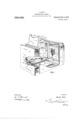
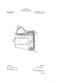
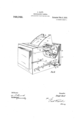
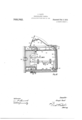
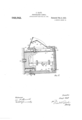
- FIG. 1 is a perspective view of a camera with parts broken away.
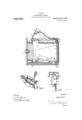
- Fig. 2 a sectional elevation of the same.
- Fig. 3 a perspective view of operating mechanism and
- Fig. 4 an elevation of the shutter attachment.
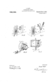
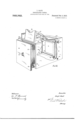
- Figs. 5 (S and 7 are partial perspective views respectively of constructions of cameras wherein the principal improvement hereof is applied in modified form and
- Fig. 8 is a perspective view of the focusing leaf.
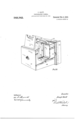
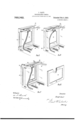
- Figs. 9, 10 and 11 are perspective "iews of a modified construction of a camera with these present improvements and
- Fig. 12 a sectional elevation of Fig. 11.
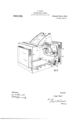
- Fig. 13 is a perspective view of a further modified construction of camera according to this invention and
- Fig. 14 a sectional elevation thereof.
- Fig. 15 is a sectional elevation of a further modified con struction of camera according to this invention and Figs. 16 and 17 are partial perspective views respectively of devices for operating the compensating-mechanism of the box of the camera according to this invention.
- Figs. 18 and 19 are perspective and side views respectively of devices for operating the lens of cameras according to this inven tion.
- Fig. 20 is a perspective view of a further modified construction of camera (in this case a folding camera) according to this invention and Fig. 21 is a sectional elevation thereof.
- Fig. 22 a perspective view of a further modified construction of camera (in this case a magazine camera) according to this invention and Fig. 23 a sectional elevation thereof.
- the body 25 is attached to the lens plate or head 26 by a bellows 27,
- the mentioned finger 34 engages with a pin 41 on a lever 42 fulcrumed at 43 to the body of a camera and with a stop pin 44 on the camera body.
- the other end of this lever 42 bears upon spring 45 and has a stop end 46 engagin with the lower end of the focusing leaf 47 having an opaque and preferably a white surface 51) in its lowermost position.
- This leaf 47 is fast on a spindle 48 having bearings in the sides of the camera body and having an operating head 49.
- This spindle 48 has also around it a double ended spring 50 with one end stationary and fast to the camera body, while the other end is fast to the leaf 47, so that when the stop 46 is depressed and released said leaf will be elevated by said spring 50 into out-ofaction position (as in Fig.
- the camera has a top cover 60 to allow of access to the leaf 47 to manipulate the mask 59, and in said cover 60 a rectangular orifice 61 is cut, and above this is fixed a hinged flap 65 with collapsible sides or wings (33 and a forehead rest 64.
- This [lap 65 receives, in a groove and catch not shown, a flap 67 which contains eye holes 68 (in which if desired are fitted magnifying lenses) and is hinged to the flap 62 hinged against the back edge of the orifice 61.
- the back piece 62 is adapted, when out of use, with the flap 67 folded under, to lie flat on the top of the camera cover 60.
- the camera In operation the camera is set by the leaf 17 being depressed (see Fig. 1) with the stop end 16 securing it in position to show the white opaque surface 51 toward the lens 70. If an instantaneous picture is required the shutter 56 is also set, as well understood, in front of the prepared photographic plate or film or surface 71 and the whole is ready for action. The desired picture is focused on the opaque surface 51 of the leaf s7 and is seen through the eye holes (38 by the operator leaning over the back of the camera with his forehead resting in concave (a, the image appearing in a natural or uninverted position though actually it is inverted, the focal distance being adjusted by the manipulation of the milled head 40 as well understood.
- the camera is operated as follows, the lever 37 is pressed forwardly until finger 3% reaches stop pin 11 causing the grip 88 to hold on collar 39 of spindle 31 and to revolve it so as to draw the head 26 with lens 7 0 backward the proper distance to compensate the focal dis tance of the surface 51 of leaf 4:7 and of plate '71, iving the just previously regulated focal distance to the plate or film 71.
- This movement by means of arm 31 and pin 11 releases the catch 4:6 and allows the leaf 1-7 to fly up out of the way, and this elevation of the leaf 17 operates, by pendant the spring of the shutter 56 to expose the photographic surface.
- the opaque white surface 51 of leaf 47 is a card or enameled plate fitted in the press back '72 which is adapted to occupy the re Listes 66 in which the ordinary dark slide, sliding in front of said press back 72, is placed before exposure of the plate.
- the opaque white surface 51 of leaf 4:7 is fitted in a. grooved frame 57 which, in this case, is adapted to slide in the same grooves 7 3 in which the ordinary dark slide is placed before exposure of the plate.
- the opaque white surface 51 of the leaf 47 in its frame 57 is hung by double hinges 7 .1 to the reversing back 75 of the camera so that it the charged dark slide containing the photographic plate in the vacant space.
- Fig. 8 shows the construction of grooved frame 57 containing the focusing leaf 17.
- Figs. 9 and 10 are similarly constructed to those described in Figs. 1 to 1-, with the exception that the shutter 56 and its appurtenances are placed between the focusing leaf -17 and the lens 70.
- a disk or shutter 78 having at its lower curve a tooth or nick 7%) for the spring catch 80 fulcrumed at 81 to the bellows back 77 and bearing against a spring 82.
- Pivoted to the catch 80 and depending therefrom is a vertical rod or arm 83 having fulcrumed at its lower end an arm 81- adapted to engage with the finger or radial arm on the collar 35 of spindle 31.
- the shutter 78 closes the orifice 8G in the back '77 by action of the spring 85 when the spring catch 80 releases it.
- the pin 87 is operated by the elevating of leaf 47 and causes the shutter 78 to uncover the orifice 86.
- the camera is set by the leaf 47 being depressed (see Fig. 9) with stop end as securing it in position showing the white opaque surface 51 toward the lens 70.
- This movement of the leaf 47 leaves the shutter 78 upward of the orifice 80 and clear of it with the catch 80 in gear with it.
- the rear lens shutter 56 is also set as well understood in front of the orifice S6 in the bellows back 77.
- the desired picture being focused. the operator presses forward the lever 37, causing the piece 38 to grip the collar 39 of the spindle 31 and to revolve it. so that finger 7 G engaging with the arm 84: of depending arm 83 operates the spring catch 80.
- the cameras shown in Figs. 11 and 12 are similarly constructed to those described in Figs. 1 to 1 and Figs. 9 and 10, but the shutter 78 and its operating mechanism are dispensed with, and a sector division or shield of the camera substituted.
- This sec tor shield 90 has an orifice 91, and it abuts both sides of the camera body, with the lower edge of the leaf 47 traveling over its surface.
- the rear lens shutter 56 is posimay be swung outward in order to place tioned between the shield 90 and the bellows back 77, and is operated by the release of the spring catch 53 by the leaf 47.
- the operation of taking the picture is the same as that described in Figs. 1 to 4, the orifice 91 allowing the light rays to pass to the focusing leaf and to the sensitive plate, while the sector shield 90 prevents light, other than that passing through the lens 70, from reaching the sensitive plate.
- the compensation of the focal distances of the focusing and sensitive surfaces is achieved by means of the traveling or movable frame 93 in front of and surrounding the bellows 27.
- This frame 93 supports the spindle 31 of the pinions 30 for adjusting the focus, and to it is secured a sliding bar 94. in runners or brackets
- This slide 94L engages with the catch stop 46 above the spring 45 on pivoted lever 96, and it also has a. nick 97 for the holding spring catch 98.
- On the camera body is a spring latch 99 having a press pin 100 passing through to the outside and having a catch 101 adapted to engage with the homing 102 recessed in the movable frame 93.
- a recess 104C for the inwardly drawing springs 105 connecting the movable frame 93 with the body 25, and a binding or set screw 106 is provided to make a fast temporary connection between the frame 93 and the focusing frame 28.
- the construction of the spy hole hood on top of the camera is identical with that hereinbefore described with reference to Figs. 1 to 4, and in these figures, 13 and 14, the parts bear similar distinguishing letters to those in the earlier figures and perform eX- actly similar functions.
- the movable frame 93 is drawn out until the catch 101 engages with its homing 102.
- the movable frame 93 is locked to the sliding frame 28 by the binding screw 106, the pin 100 is pressed to release the catch 101 from the homing 102, and the springs 105 immediately draw in the frame 93 and the focusing frame 28 locked thereto at the same time the slide 9% operating lever 96 to catch 40 releases the opaque leaf 47, and this in turn operates the focal plane shutter as before described.
- the camera shown in Fig. 15 is of the same construction as that described with reference to the two previous Figs. 13 and let, and the parts bear similar distinguishing characters. But in this latter make of camera the recesses 10% and the indrawing springs 105 are dispensed with in favor of a positive indrawing of the frame 93, and the focusing frame 28 locked to it by binding screw 106. This positive movement is imparted by the hands of the operator at the back of the camera and upon the angle pieces 107 on either side of the frame 93, as shown in Figs. 15 and 16.
- Figs. 18 and 19 One method of achieving this object is depicted in Figs. 18 and 19.
- the lens ring 112 slides in the sleeve 113 attached to the head 26, and it has a fixed back collar or step 114; and a forward adjustable collar 115 with a set screw 116 to enable adjustment.
- collar 115 On collar 115 are pintles 117 which engage slotted radial arms 118 affixed to a spindle 119, ournaled in bearings 120 on the head 26, and operatable by milled head 121.
- the focusing leaf 17 is elevated by nut head 19, and then the lens ring, by operating the head 121, is drawn inwardly to compensate the focal distance as beforementioned.
- the back 123 carrying the sensitized plates has a frame 124 telescoping the camera back frame 125, and is held in extended position with the leaf 17 by means of a spring latch.
- the focus of the desired picture is set by observation through a spy hole hood, of the construction before described, held on a folding frame 127 above an aperture in the top of the flexible camera body 128.
- a spring latch (not shown) is released and the camera back frame 125 and the plate frame drawn together by means of angle or finger plates such as described with reference to 1G and 17 and so compensating the focal distances.
- the back frame operates lever 42 and stop 46, releasing the focusing leaf 47, which in turn operates the focal plane shut ter 56 as beforedescribed.
- the load box 130 contains the plates or films to be used with spring 131 showing behind them.
- the hinged cover 132 of the box 133 is shown as closed thereon, with the projecting arm 13: keeping it so closed while the leaf 4:? with its opaque surface 51 is exposed to the lens, and at the same time closing the box 1213 from the light.
- the focus having been set the leaf at? is released by head 135 moving the catch 46 outof the way, and is sprung elevated with the projecting arm 134 which, leaving the cover 132, allows this latter also to fly up, opening the box 133 to receive the plate or film after its exposure.
- the leaf 47 is then returned to focusing position, bringing with it the cover 132 on to the box 133.
- a photographic camera having means for holding a sensitive element for exposure, and a lens movable toward and from the same for focusing purposes.
- an opaque focusing plate pivotally mounted within the camera and adapted, when in focusing position, to cover the sensitive element, said :amera having an opening in its top for directly viewing said opaque focusing plate, means for effecting the adjustment of the lens to aid the sensitive element a distance equal to the distance between the focusing plate and the sensitive element, and means operated automatically on the completion of such adjustment for swinging the focusing surface away from the sensitive element.
- a photographic camera having a lens and means for holding a sensitive element, said parts being movable with relation to each other for focusing purposes, an opaque focusing plate, means for removably holding said plate in front of the sensitive element, said camera having an opening in its top through which the opaque plate may be directly viewed, means whereby the lens and sensitive element may be adjusted toward each other a distance corresponding to the distance between the opaque and sensitive elements, means whereby, upon the completion of said adjustment, the opaque focusing plate will be removed from in front of the sensitive. element, a shutter, and means whereby the same is automatically operated upon the remo 'al of the focusing plate, substantially as described.
- a camera having means for holding a sensitive clement, an opaque focusing plate pivotally mounted in front of said sensitive element, said camera having an opening in its top for directly viewing the focusing plate, and means whereby the focusing plate may be removed from in front of the sensitive element and caused to close the opening in the top of the camera, substantially as described.
- a camera having means for holding a sensitive element, an opaque focusing plate pivotally mounted at the upper portion of the camera, and adapted to depend normally to cover said sensitive element, said camera having an opening in its top for directly viewing said opaque focusing plate, spring means tending to swing said focusing plate upward away from said sensitive element to close said opening, a lens adjustable to ard and from the sensitive element, means for adjusting said lens toward the sensitive element an amount equal to the distance between the focusing plate and the sensitive element, and means whereby, on the completion of said adjustment, the opaque focusing plate is released and allowed to close the opening in the top of the camera, substantially as described.
- a camera having means for holding a sensitive element, an opaque focusing plate pivotally mounted in front of said holding means, said camera having an opening in its top for directly viewing the focusing plate a spring exerting tension on said opaque focusing plate tending to raise it into horizontal position to close the opening in the top of the came a, a locking lever for holding the focusing plate down against the tension of the spring, means for adjusting the lens a definite amount toward the sensitive element, and means whereby said adjustment operates the locking lever, substantially as described.
- a photographic camera having means for holding a sensitive element, an opaque focusing plate, means for removably holding said plate in front thereof, and an opening in the top of the camera for directly viewing said opaque plate, and a folding hood above the camera about said opening, said hood comprising a member hinged to the camera and having an edge shaped to receive the forehead of the operator and an angular extension provided with sight openings and a second member hinged to said extension, substantially as described.
- a photographic camera having means for holding a sensitive element, an opaque focusing plate pivotally mounted in the top of the camera and adapted to depend over said sensitive plate holding means, a shaft upon which said focusing plate is mounted, provided with an operating handle, a spring tending to turn said shaft to swing the focusing plate up against the top of the camera, the top of the camera having an opening for directly viewing said focusing plate, said opening being closed by focusing plate
- the lens is moved a the plate when the latter is raised, a rocking determined distance toward the latter, sublever for holding the focusing plate down stantially as described. to cover the sensitive element, a lens and In testimony whereof I have signed my 5 bellows, a rack and gear connection for adname to this specification in the presence of 15 justing said lens, a shaft for moving said two subscribing witnesses.
Landscapes
- Physics & Mathematics (AREA)
- General Physics & Mathematics (AREA)
- Cameras In General (AREA)
Description
Wiinesse:
WWW.
J. GAUT.
PHOTOGRAPHIO CAMERA.
APPLIOATION FILED MAR. 20. 1908.
15 SHEETS-SHEET 1.
[raven/or Patented Feb. 8,19101 J. GAUT.
PHOTOGRAPHIC UAMEHA.
APPLICATION FILED MAR. 20, 1908 948,942. Patented Feb. 8, 1910.
15 SHBETSSHEET 2.
IIIIIIIIIIIIIIII{III/III!IIIIIIIIIIIl/IIIIIIIIII Wiirwues Im efifw" 60. M 1 (Ilse 12$ Gan? J. GAUT.
PHOTOGRAPHIG CAMERA.
APPLICATION FILED MAR. 20, 190B Patented Feb. 8, 1910.
15 SHEETS-SHEET 3.
Wifnusex J. GAUT.
PHOTOGRAPHIG CAMERA.
APPLICATION FILED MAR. 20, 1908.
Patented Feb. 8, 1910.
15SHEETS-SHBBT 4.
Witnesses J. GAUT.
PHOTOGRAPHIG CAMERA.
APPLICATION FILED MAR. 20, 1908.
Patented Feb. 8, 1910.
15 SHEETS-SHBET 5.
Wifilessa www J. GAUT.
PHOTOGRAPHIU CAMERA.
APPLICATION FILED MAR. 20. 1908.
Patented Feb.8, 1910.
15 SHEETS-SHEET 6.
Mine was J. GAUT.
PHOTOGRAPHIG CAMERA.
APPLICATION FILED MAR.20,1908.
Patented Feb. 8. 1910.
15 SHEEN-SHEET 7.
I I I Wifnesse: 60. n fl 4 J. GAUT.
PHOTOGRAPHIO CAMERA.
APPLIOATION FILED MAR. 20. 1908.
Patented Feb. 8, 1910.
15 SHEETS-SHEET 8 J. GAUT.
PHOTOGRAPHIO CAMERA.
APPLICATION FILED MAR. 20, 190av Patented Feb. 8, 1910.
15 SHEETS-SHEET 9 Int/0270f a my? 6am" g/M J. GAUT.
PHOTOGRAPHIG CAMERA.
APPLICATION FILED MAR. 20, 1908.
Patented Feb. 8, 1910.
15 SHEETS-SHEBT 1o.
J. GAUT.
PHOTOGRAPHIG CAMERA.
APPLICATION FILED MAR. 20. 1908.
948,942. Patented Feb.8,1910.
15 SHEETS-SHBET ll.
W1712esse: [772/4272 fir J. GAUT.
PHOTOGRAPHIG CAMERA.
APPLICATION FILED MAR. 20, 1908.
Patented Feb. 8, 1910.
15 SHEETS-SHEET 12.
Wz'fnesre:
WWW.
J. GAUT.
PHOTOGRAPHIC CAMERA.
APPLICATION FILED MAR. 20, 1908.
15 SHEETS-SHEET 13.
k. GAUT.
PHOTOGRAPHIC CAMERA.
APPLICATION FILED MAR. 20, 1908.
Patented Feb. 8, 1910.
15 $HBETS-SHEBT 14.
WM MM/ l GAUT.
PHOTOGRAPHIU CAMERA.
APPLICATION FILED MAR. 20, 1908,
948,942. Patented Feb. 8, 1910.
15 SHEETS-SHEET 15.
NHW 07 0(7 Q wWM UNITED STATES PATENT OFFICE.
JOSEPH GAUT, OF LEICHHARDT, NEAR SYDNEY, NEW SOUTH WALES, AUSTRALIA, ASSIGNOR OF ONE-HALF T HARRINGTON AND COMPANY LIMITED, OF SYDNEY, AUSTRALIA, A COMPANY OF NEW SOUTH WALES.
PHOTOGRAPHIC CAMERA.
To all whom it may concern:
Be it known that I, J OSEPH GAUT, of No. 3 Gary street, Leichhardt, near Sydney, in
' the State of New South ales, in the Commonwealth of Australia, artist, have invent ed new and useful Improvements in Photographic Cameras, of which the following is a specification.
My said invention relates to improvements in focusing cameras, and comprises the novel features of construction and arrangement and combination of parts hereinafter described and particularly set forth in the appended claims.
My invention is illustrated in the accompanying drawings in which Figure 1 is a perspective view of a camera with parts broken away. Fig. 2 a sectional elevation of the same. Fig. 3 a perspective view of operating mechanism and Fig. 4 an elevation of the shutter attachment. Figs. 5 (S and 7 are partial perspective views respectively of constructions of cameras wherein the principal improvement hereof is applied in modified form and Fig. 8 is a perspective view of the focusing leaf. Figs. 9, 10 and 11 are perspective "iews of a modified construction of a camera with these present improvements and Fig. 12 a sectional elevation of Fig. 11. Fig. 13 is a perspective view of a further modified construction of camera according to this invention and Fig. 14 a sectional elevation thereof. Fig. 15 is a sectional elevation of a further modified con struction of camera according to this invention and Figs. 16 and 17 are partial perspective views respectively of devices for operating the compensating-mechanism of the box of the camera according to this invention. Figs. 18 and 19 are perspective and side views respectively of devices for operating the lens of cameras according to this inven tion. Fig. 20 is a perspective view of a further modified construction of camera (in this case a folding camera) according to this invention and Fig. 21 is a sectional elevation thereof. Fig. 22 a perspective view of a further modified construction of camera (in this case a magazine camera) according to this invention and Fig. 23 a sectional elevation thereof.
In the construction of camera shown in Figs. 1, 2, 3 and 4 the body 25 is attached to the lens plate or head 26 by a bellows 27,
Specification of Letters Patent.
Application filed. March 20, 1908.
Patented Feb. 8, 1910.
Serial No. 422,296.
which head 26 is fast to the sliding plate 28 carrying toothed racks 29 in which gear the pinions 30 on spindle 31 on bearings in the sides of the camera body. One end of spin dle 31 passes through a loose sleeve 32 (see Fig. 3) carrying coil spring attached at one end to the body of the came a and at the other to a finger or radial arm 34 on the collar 35 of sleeve 32. This sleeve 32 has a flange 36 to which is pivoted the lever or thumb piece or operating finger 3'? having a semi-circular gripping piece 38 around the boss 39 of said spindle 31 which terminates in the milled focus-regulating head 40. The mentioned finger 34 engages with a pin 41 on a lever 42 fulcrumed at 43 to the body of a camera and with a stop pin 44 on the camera body. The other end of this lever 42 bears upon spring 45 and has a stop end 46 engagin with the lower end of the focusing leaf 47 having an opaque and preferably a white surface 51) in its lowermost position. This leaf 47 is fast on a spindle 48 having bearings in the sides of the camera body and having an operating head 49. This spindle 48 has also around it a double ended spring 50 with one end stationary and fast to the camera body, while the other end is fast to the leaf 47, so that when the stop 46 is depressed and released said leaf will be elevated by said spring 50 into out-ofaction position (as in Fig. 2) resting against combing or light guard boxing 52. The elevation of this leaf 47 acting against pendant 53 operates the spring detent 54 and releases it from the ratchet 5.5 of the coil spring roller of the focal plane shutter 56. The leaf 47 has lips 58 forming grooves for the black mask 59 toward the lens. The camera has a top cover 60 to allow of access to the leaf 47 to manipulate the mask 59, and in said cover 60 a rectangular orifice 61 is cut, and above this is fixed a hinged flap 65 with collapsible sides or wings (33 and a forehead rest 64. This [lap 65 receives, in a groove and catch not shown, a flap 67 which contains eye holes 68 (in which if desired are fitted magnifying lenses) and is hinged to the flap 62 hinged against the back edge of the orifice 61. The back piece 62 is adapted, when out of use, with the flap 67 folded under, to lie flat on the top of the camera cover 60.
In operation the camera is set by the leaf 17 being depressed (see Fig. 1) with the stop end 16 securing it in position to show the white opaque surface 51 toward the lens 70. If an instantaneous picture is required the shutter 56 is also set, as well understood, in front of the prepared photographic plate or film or surface 71 and the whole is ready for action. The desired picture is focused on the opaque surface 51 of the leaf s7 and is seen through the eye holes (38 by the operator leaning over the back of the camera with his forehead resting in concave (a, the image appearing in a natural or uninverted position though actually it is inverted, the focal distance being adjusted by the manipulation of the milled head 40 as well understood. But to insure that the surface of the photographic plate or sensitive film 71 will, at the proper moment, occupy the position of the opaque surface 51 of the leaf 47, the camera is operated as follows, the lever 37 is pressed forwardly until finger 3% reaches stop pin 11 causing the grip 88 to hold on collar 39 of spindle 31 and to revolve it so as to draw the head 26 with lens 7 0 backward the proper distance to compensate the focal dis tance of the surface 51 of leaf 4:7 and of plate '71, iving the just previously regulated focal distance to the plate or film 71. This movement by means of arm 31 and pin 11 releases the catch 4:6 and allows the leaf 1-7 to fly up out of the way, and this elevation of the leaf 17 operates, by pendant the spring of the shutter 56 to expose the photographic surface.
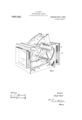
In the modified construction of came as shown in Figs. 5, 6 and 7 the focal distances between the focusing and photo graphing surfaces are the same under all circumstances, the photographing surface '71 of the plate or film being in exactly the same plane as the surface 51 of the focusing leaf 17. Each of these cameras has the front lens and the usual focusing arrangements. A spy hole aperture and hood on top is constructed similarly, and has orifice 61, fiap (J2, collapsible sides 63, flap 67, spy holes (38, and hinged flap (35 and cover (10. In Fig. 5 the opaque white surface 51 of leaf 47 is a card or enameled plate fitted in the press back '72 which is adapted to occupy the re cesses 66 in which the ordinary dark slide, sliding in front of said press back 72, is placed before exposure of the plate. In Fig. 6 the opaque white surface 51 of leaf 4:7 is fitted in a. grooved frame 57 which, in this case, is adapted to slide in the same grooves 7 3 in which the ordinary dark slide is placed before exposure of the plate. In Fig. 7 the opaque white surface 51 of the leaf 47 in its frame 57 is hung by double hinges 7 .1 to the reversing back 75 of the camera so that it the charged dark slide containing the photographic plate in the vacant space.
Fig. 8 shows the construction of grooved frame 57 containing the focusing leaf 17.
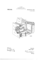
The cameras shown in Figs. 9 and 10 are similarly constructed to those described in Figs. 1 to 1-, with the exception that the shutter 56 and its appurtenances are placed between the focusing leaf -17 and the lens 70. To the bellows back 77 is pivoted a disk or shutter 78 having at its lower curve a tooth or nick 7%) for the spring catch 80 fulcrumed at 81 to the bellows back 77 and bearing against a spring 82. Pivoted to the catch 80 and depending therefrom is a vertical rod or arm 83 having fulcrumed at its lower end an arm 81- adapted to engage with the finger or radial arm on the collar 35 of spindle 31. The shutter 78 closes the orifice 8G in the back '77 by action of the spring 85 when the spring catch 80 releases it. The pin 87 is operated by the elevating of leaf 47 and causes the shutter 78 to uncover the orifice 86.
In operation the camera is set by the leaf 47 being depressed (see Fig. 9) with stop end as securing it in position showing the white opaque surface 51 toward the lens 70. This movement of the leaf 47 leaves the shutter 78 upward of the orifice 80 and clear of it with the catch 80 in gear with it. If an instantaneous picture is required the rear lens shutter 56 is also set as well understood in front of the orifice S6 in the bellows back 77. The desired picture being focused. the operator presses forward the lever 37, causing the piece 38 to grip the collar 39 of the spindle 31 and to revolve it. so that finger 7 G engaging with the arm 84: of depending arm 83 operates the spring catch 80. and releases the shutter 7 8 causing it to cover the orifice 86, as shown in dotted lines in Fig. 9. and simultaneously draws the head 26 with lens 70 backwardly, which compensates the focal distance of the surfaces 51 and of plate 71. The arm 34 and pin -l1 release the catch 416, allow the. leaf 17 to fly up clear of lines of light rays through orifice S6, operate the pin 87 (lifting the disk 78) thereby uncovering the orifice 8(3. and simultaneously the leaf 17 operates the spring catch of the rear lens shutter 56 to eX pose the sensitive surface.
The cameras shown in Figs. 11 and 12 are similarly constructed to those described in Figs. 1 to 1 and Figs. 9 and 10, but the shutter 78 and its operating mechanism are dispensed with, and a sector division or shield of the camera substituted. This sec tor shield 90 has an orifice 91, and it abuts both sides of the camera body, with the lower edge of the leaf 47 traveling over its surface. The rear lens shutter 56 is posimay be swung outward in order to place tioned between the shield 90 and the bellows back 77, and is operated by the release of the spring catch 53 by the leaf 47. The operation of taking the picture is the same as that described in Figs. 1 to 4, the orifice 91 allowing the light rays to pass to the focusing leaf and to the sensitive plate, while the sector shield 90 prevents light, other than that passing through the lens 70, from reaching the sensitive plate.
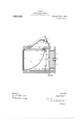
In the cameras shown in Figs. 13 and 1% the compensation of the focal distances of the focusing and sensitive surfaces is achieved by means of the traveling or movable frame 93 in front of and surrounding the bellows 27. This frame 93 supports the spindle 31 of the pinions 30 for adjusting the focus, and to it is secured a sliding bar 94. in runners or brackets This slide 94L engages with the catch stop 46 above the spring 45 on pivoted lever 96, and it also has a. nick 97 for the holding spring catch 98. On the camera body is a spring latch 99 having a press pin 100 passing through to the outside and having a catch 101 adapted to engage with the homing 102 recessed in the movable frame 93. In the camera body 25 backward of the frame 93 is a recess 104C for the inwardly drawing springs 105 connecting the movable frame 93 with the body 25, and a binding or set screw 106 is provided to make a fast temporary connection between the frame 93 and the focusing frame 28. The construction of the spy hole hood on top of the camera is identical with that hereinbefore described with reference to Figs. 1 to 4, and in these figures, 13 and 14, the parts bear similar distinguishing letters to those in the earlier figures and perform eX- actly similar functions. To set these cameras the movable frame 93 is drawn out until the catch 101 engages with its homing 102. After focusing the desired picture in the ordinary way by regulating spindle 31, the movable frame 93 is locked to the sliding frame 28 by the binding screw 106, the pin 100 is pressed to release the catch 101 from the homing 102, and the springs 105 immediately draw in the frame 93 and the focusing frame 28 locked thereto at the same time the slide 9% operating lever 96 to catch 40 releases the opaque leaf 47, and this in turn operates the focal plane shutter as before described.
The camera shown in Fig. 15 is of the same construction as that described with reference to the two previous Figs. 13 and let, and the parts bear similar distinguishing characters. But in this latter make of camera the recesses 10% and the indrawing springs 105 are dispensed with in favor of a positive indrawing of the frame 93, and the focusing frame 28 locked to it by binding screw 106. This positive movement is imparted by the hands of the operator at the back of the camera and upon the angle pieces 107 on either side of the frame 93, as shown in Figs. 15 and 16. It may also be imparted by pressure on the thumb piece of the bell crank lever 108, which is pivoted to the camera body and engages, in its slot 109, the fast pin 110 on the moving frame 93, with the result that said frame would be drawn into the body 25 (see Fig. 17). lVhile itis necessary that compensation between the Varying focal distances of the focusing and photographing surfaces should take place, it is not essential according to this invention that such should be achieved by any move ment of the camera body or appurtenances thereto, for instead a movement in or of the lens itself may be made in respect of this compensation so that at the moment of exposure the photographic surface will be the same focal distance from the lens as the opaque white focusing surface originally was. One method of achieving this object is depicted in Figs. 18 and 19. The lens ring 112 slides in the sleeve 113 attached to the head 26, and it has a fixed back collar or step 114; and a forward adjustable collar 115 with a set screw 116 to enable adjustment. On collar 115 are pintles 117 which engage slotted radial arms 118 affixed to a spindle 119, ournaled in bearings 120 on the head 26, and operatable by milled head 121. The focusing leaf 17 is elevated by nut head 19, and then the lens ring, by operating the head 121, is drawn inwardly to compensate the focal distance as beforementioned.
In the folding camera illustrated in Figs. 20 and 21 the back 123 carrying the sensitized plates has a frame 124 telescoping the camera back frame 125, and is held in extended position with the leaf 17 by means of a spring latch. The focus of the desired picture is set by observation through a spy hole hood, of the construction before described, held on a folding frame 127 above an aperture in the top of the flexible camera body 128. After adjusting the focus a spring latch (not shown) is released and the camera back frame 125 and the plate frame drawn together by means of angle or finger plates such as described with reference to 1G and 17 and so compensating the focal distances. The back frame operates lever 42 and stop 46, releasing the focusing leaf 47, which in turn operates the focal plane shut ter 56 as beforedescribed.
In the magazine camera, Figs. 22 and 23, the opaque leaf 4L7 in its frame 57 n'iight be inserted through an opening with internal slides to occupy the position of the sensitive plate or film when in actual photographic use. But another method of achieving the object will be described in reference to Figs. 22 and 23 wherein the various parts of similar function are distinguished by the numbers referred to in the description of such parts in'the other figures of the drawings.
The load box 130 contains the plates or films to be used with spring 131 showing behind them. In Fig. the hinged cover 132 of the box 133 is shown as closed thereon, with the projecting arm 13: keeping it so closed while the leaf 4:? with its opaque surface 51 is exposed to the lens, and at the same time closing the box 1213 from the light. The focus having been set the leaf at? is released by head 135 moving the catch 46 outof the way, and is sprung elevated with the projecting arm 134 which, leaving the cover 132, allows this latter also to fly up, opening the box 133 to receive the plate or film after its exposure. The leaf 47 is then returned to focusing position, bringing with it the cover 132 on to the box 133. In this described camera there is no compensation of focal distance as the focusing opaque surface occupies the position of the oncoming plate or film. But if such compensation were required it could be achieved by the movement of a frame such at. 93 hereinbefore mentioned or by other means as described herein.
Having thus described my invention what I claim is 1. A photographic camera having means for holding a sensitive element for exposure, and a lens movable toward and from the same for focusing purposes. an opaque focusing plate pivotally mounted within the camera and adapted, when in focusing position, to cover the sensitive element, said :amera having an opening in its top for directly viewing said opaque focusing plate, means for effecting the adjustment of the lens to aid the sensitive element a distance equal to the distance between the focusing plate and the sensitive element, and means operated automatically on the completion of such adjustment for swinging the focusing surface away from the sensitive element.
'2. A photographic camera having a lens and means for holding a sensitive element, said parts being movable with relation to each other for focusing purposes, an opaque focusing plate, means for removably holding said plate in front of the sensitive element, said camera having an opening in its top through which the opaque plate may be directly viewed, means whereby the lens and sensitive element may be adjusted toward each other a distance corresponding to the distance between the opaque and sensitive elements, means whereby, upon the completion of said adjustment, the opaque focusing plate will be removed from in front of the sensitive. element, a shutter, and means whereby the same is automatically operated upon the remo 'al of the focusing plate, substantially as described.
9). A camera having means for holding a sensitive clement, an opaque focusing plate pivotally mounted in front of said sensitive element, said camera having an opening in its top for directly viewing the focusing plate, and means whereby the focusing plate may be removed from in front of the sensitive element and caused to close the opening in the top of the camera, substantially as described.
4. A camera having means for holding a sensitive element, an opaque focusing plate pivotally mounted at the upper portion of the camera, and adapted to depend normally to cover said sensitive element, said camera having an opening in its top for directly viewing said opaque focusing plate, spring means tending to swing said focusing plate upward away from said sensitive element to close said opening, a lens adjustable to ard and from the sensitive element, means for adjusting said lens toward the sensitive element an amount equal to the distance between the focusing plate and the sensitive element, and means whereby, on the completion of said adjustment, the opaque focusing plate is released and allowed to close the opening in the top of the camera, substantially as described.
A camera having means for holding a sensitive element, an opaque focusing plate pivotally mounted in front of said holding means, said camera having an opening in its top for directly viewing the focusing plate a spring exerting tension on said opaque focusing plate tending to raise it into horizontal position to close the opening in the top of the came a, a locking lever for holding the focusing plate down against the tension of the spring, means for adjusting the lens a definite amount toward the sensitive element, and means whereby said adjustment operates the locking lever, substantially as described.
(3, A photographic camera having means for holding a sensitive element, an opaque focusing plate, means for removably holding said plate in front thereof, and an opening in the top of the camera for directly viewing said opaque plate, and a folding hood above the camera about said opening, said hood comprising a member hinged to the camera and having an edge shaped to receive the forehead of the operator and an angular extension provided with sight openings and a second member hinged to said extension, substantially as described.
7. A photographic camera having means for holding a sensitive element, an opaque focusing plate pivotally mounted in the top of the camera and adapted to depend over said sensitive plate holding means, a shaft upon which said focusing plate is mounted, provided with an operating handle, a spring tending to turn said shaft to swing the focusing plate up against the top of the camera, the top of the camera having an opening for directly viewing said focusing plate, said opening being closed by focusing plate When the lens is moved a the plate when the latter is raised, a rocking determined distance toward the latter, sublever for holding the focusing plate down stantially as described. to cover the sensitive element, a lens and In testimony whereof I have signed my 5 bellows, a rack and gear connection for adname to this specification in the presence of 15 justing said lens, a shaft for moving said two subscribing witnesses.
rack and gear connection provided With a JOSEPH GAUT. suitable operating handle, and an arm oper- Vitnesses: ated by said shaft adapted to cooperate with W. M. LEAN,
10 said lever to cause the latter to release the C. N. HANDRIGK.
Priority Applications (1)
| Application Number | Priority Date | Filing Date | Title |
|---|---|---|---|
| US42229608A US948942A (en) | 1908-03-20 | 1908-03-20 | Photographic camera. |
Applications Claiming Priority (1)
| Application Number | Priority Date | Filing Date | Title |
|---|---|---|---|
| US42229608A US948942A (en) | 1908-03-20 | 1908-03-20 | Photographic camera. |
Publications (1)
| Publication Number | Publication Date |
|---|---|
| US948942A true US948942A (en) | 1910-02-08 |
Family
ID=3017357
Family Applications (1)
| Application Number | Title | Priority Date | Filing Date |
|---|---|---|---|
| US42229608A Expired - Lifetime US948942A (en) | 1908-03-20 | 1908-03-20 | Photographic camera. |
Country Status (1)
| Country | Link |
|---|---|
| US (1) | US948942A (en) |
Cited By (1)
| Publication number | Priority date | Publication date | Assignee | Title |
|---|---|---|---|---|
| US3473457A (en) * | 1966-11-01 | 1969-10-21 | Comitetul De Stat Pentru Cultu | Viewfinder for cameras with optical pickup from film surface |
-
1908
- 1908-03-20 US US42229608A patent/US948942A/en not_active Expired - Lifetime
Cited By (1)
| Publication number | Priority date | Publication date | Assignee | Title |
|---|---|---|---|---|
| US3473457A (en) * | 1966-11-01 | 1969-10-21 | Comitetul De Stat Pentru Cultu | Viewfinder for cameras with optical pickup from film surface |
Similar Documents
| Publication | Publication Date | Title |
|---|---|---|
| US2043900A (en) | Multiple image view finder | |
| US2348510A (en) | Camera | |
| US2206132A (en) | Focusing attachment for shutters | |
| DE675275C (en) | Light shaft designed as a frame finder for overhead viewers of photographic cameras | |
| US2641955A (en) | Focusing hood for photographic cameras | |
| US1284980A (en) | Reflecting-camera. | |
| US1174014A (en) | Focusing device for cameras. | |
| US1962321A (en) | Viewing and focus-finding device for cameras | |
| US1307512A (en) | Photographic camera | |
| US2518718A (en) | Twin-lens reflex camera | |
| US246164A (en) | Alphonse loiseau | |
| US3126806A (en) | Mirror control arrangement for reflex cameras | |
| US1984103A (en) | Reflex finder for motion picture cameras | |
| US497884A (en) | Photographic-negative ribbon for camera-boxes | |
| US1023931A (en) | Camera. | |
| US3089399A (en) | Cameras | |
| US2936688A (en) | Photographic reflex camera | |
| US308468A (en) | Walter claek | |
| US1024200A (en) | Photographic camera. | |
| US922411A (en) | Focusing attachment for cameras. | |
| US2843031A (en) | Viewing hood and cover for photographic camera | |
| EP0318888A1 (en) | Mirror system for a single lens reflex camera | |
| US2043968A (en) | Camera construction | |
| JPS607253B2 (en) | Text imprinting device for single-lens reflex camera | |
| US1314030A (en) | Focusing attachment fob cameras |