US9484662B2 - Electrical connector with improved terminal module - Google Patents
Electrical connector with improved terminal module Download PDFInfo
- Publication number
- US9484662B2 US9484662B2 US14/946,706 US201514946706A US9484662B2 US 9484662 B2 US9484662 B2 US 9484662B2 US 201514946706 A US201514946706 A US 201514946706A US 9484662 B2 US9484662 B2 US 9484662B2
- Authority
- US
- United States
- Prior art keywords
- molding process
- insulator
- space
- stage insert
- contacts
- Prior art date
- Legal status (The legal status is an assumption and is not a legal conclusion. Google has not performed a legal analysis and makes no representation as to the accuracy of the status listed.)
- Active
Links
Images


Classifications
-
- H—ELECTRICITY
- H01—ELECTRIC ELEMENTS
- H01R—ELECTRICALLY-CONDUCTIVE CONNECTIONS; STRUCTURAL ASSOCIATIONS OF A PLURALITY OF MUTUALLY-INSULATED ELECTRICAL CONNECTING ELEMENTS; COUPLING DEVICES; CURRENT COLLECTORS
- H01R13/00—Details of coupling devices of the kinds covered by groups H01R12/70 or H01R24/00 - H01R33/00
- H01R13/46—Bases; Cases
- H01R13/502—Bases; Cases composed of different pieces
- H01R13/504—Bases; Cases composed of different pieces different pieces being moulded, cemented, welded, e.g. ultrasonic welding, or swaged together
-
- H—ELECTRICITY
- H01—ELECTRIC ELEMENTS
- H01R—ELECTRICALLY-CONDUCTIVE CONNECTIONS; STRUCTURAL ASSOCIATIONS OF A PLURALITY OF MUTUALLY-INSULATED ELECTRICAL CONNECTING ELEMENTS; COUPLING DEVICES; CURRENT COLLECTORS
- H01R13/00—Details of coupling devices of the kinds covered by groups H01R12/70 or H01R24/00 - H01R33/00
- H01R13/648—Protective earth or shield arrangements on coupling devices, e.g. anti-static shielding
- H01R13/658—High frequency shielding arrangements, e.g. against EMI [Electro-Magnetic Interference] or EMP [Electro-Magnetic Pulse]
- H01R13/6581—Shield structure
- H01R13/6585—Shielding material individually surrounding or interposed between mutually spaced contacts
-
- H—ELECTRICITY
- H01—ELECTRIC ELEMENTS
- H01R—ELECTRICALLY-CONDUCTIVE CONNECTIONS; STRUCTURAL ASSOCIATIONS OF A PLURALITY OF MUTUALLY-INSULATED ELECTRICAL CONNECTING ELEMENTS; COUPLING DEVICES; CURRENT COLLECTORS
- H01R13/00—Details of coupling devices of the kinds covered by groups H01R12/70 or H01R24/00 - H01R33/00
- H01R13/648—Protective earth or shield arrangements on coupling devices, e.g. anti-static shielding
- H01R13/658—High frequency shielding arrangements, e.g. against EMI [Electro-Magnetic Interference] or EMP [Electro-Magnetic Pulse]
- H01R13/6591—Specific features or arrangements of connection of shield to conductive members
- H01R13/6594—Specific features or arrangements of connection of shield to conductive members the shield being mounted on a PCB and connected to conductive members
-
- H—ELECTRICITY
- H01—ELECTRIC ELEMENTS
- H01R—ELECTRICALLY-CONDUCTIVE CONNECTIONS; STRUCTURAL ASSOCIATIONS OF A PLURALITY OF MUTUALLY-INSULATED ELECTRICAL CONNECTING ELEMENTS; COUPLING DEVICES; CURRENT COLLECTORS
- H01R2107/00—Four or more poles
-
- H—ELECTRICITY
- H01—ELECTRIC ELEMENTS
- H01R—ELECTRICALLY-CONDUCTIVE CONNECTIONS; STRUCTURAL ASSOCIATIONS OF A PLURALITY OF MUTUALLY-INSULATED ELECTRICAL CONNECTING ELEMENTS; COUPLING DEVICES; CURRENT COLLECTORS
- H01R24/00—Two-part coupling devices, or either of their cooperating parts, characterised by their overall structure
- H01R24/60—Contacts spaced along planar side wall transverse to longitudinal axis of engagement
Definitions
- the present invention relates to an electrical connector assembly, and more particularly to an electrical connector with improvements to assembling.
- Type C USB specification was issued on Aug. 11, 2014.
- the size of the receptacle connector is essentially small to replace the micro-USB connector while the number of the corresponding contacts is much more than that of micro-USB.
- all the contacts are arranged in two rows in a diagonally symmetrical manner for mating with the corresponding plug connector in a flippable manner, i.e., two orientations with the same effect.
- the traditional two stage insert-molding process as disclosed in US Pub. No. 2015/0222059 may disadvantageously have some manufacturing difficulties to remove the linking bridges between the neighboring contacts in the contact carrier for finalize the terminal module because of the existing insulator around those linking bridges.
- a new structure of the receptacle connector is desired.
- a receptacle connector for mating with the plug connector includes a terminal unit, a metallic shield and a mating cavity surrounded by the metallic shield.
- the terminal unit includes a terminal module having a first insulator with a plurality of first contacts embedded therein via a first stage insert-molding process, a second insulator with a plurality of second contacts embedded therein via the similar first stage insert-molding process, a metallic shielding plate sandwiched between the first insulator and the second insulator, and an insulative tongue piece integrally formed with a combination of the first insulator, the second insulator and the shielding plate via a second stage insert-molding process.
- the first insulator includes a first front insulator and a first rear insulator spaced from each other while linked together by the corresponding first contacts;
- the second insulator includes a second front insulator and a second rear insulator spaced from each other while linked together by the corresponding second contacts.
- the linking bridges between every adjacent two contacts are located and also easily removed in the space between the first front insulator and the first rear insulator. It is also easy to inspect whether the linking bridges are completely removed from the corresponding contacts. The space is successively filled with the material of the tongue piece.
- FIG. 1 is an assembled perspective view of a receptacle connector assembly in accordance with the present invention
- FIG. 2 is an exploded perspective view of the receptacle in FIG. 1 ;
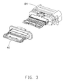
- FIG. 3 is a further exploded perspective view of the terminal unit of the receptacle connector in FIG. 2 ;
- FIG. 4 is a further exploded perspective view of the terminal unit of the receptacle connector in FIG. 3 ;
- FIG. 5 is another further exploded perspective view of the terminal unit of the receptacle connector in FIG. 3 ;
- FIG. 6 is an exploded perspective view of first terminal module and second terminal module of the receptacle connector in FIG. 5 ;
- FIG. 7 is another exploded perspective view of the first terminal module and the second terminal module of the receptacle connector in FIG. 5 .
- FIG. 8 is a cross-sectional view of the exploded terminal unit of the receptacle connector of FIG. 3
- FIG. 9 is a cross-sectional view of the assembled terminal unit of the receptacle connector of FIG. 3 .
- FIG. 10 is an elevational view of the contacts to show where the linking bridges are linked thereto.
- the receptacle connector 100 for use with a plug connector (not shown) mated with a flippable way includes a terminal unit 10 , a metallic shield 20 enclosing the terminal unit 10 , and a mating cavity 101 surrounded by the metallic shield 20 and forwardly communicating with an exterior in a front-to-back direction.
- the terminal unit 10 includes a mating tongue 103 extending into the mating cavity 101 .
- the mating cavity 101 forms an elliptical cross-section and symmetrical with regard to the mating tongue 103 so as to allow the plug connector (not shown) to be mated therewith in a flippable way.
- a metallic bracket 30 is attached upon the shield 20 for assisting mounting of the electrical connector 100 upon the printed circuit board (not shown).
- the terminal unit 10 includes a terminal module 104 and an insulative tongue piece 40 integrally formed/filled upon/within the terminal module 104 .
- the terminal module 104 includes a first/upper terminal module 60 , a second/lower terminal module 70 , a metallic shielding plate 50 sandwiched between the upper terminal module 60 and the lower terminal module 70 , and the upper metallic grounding collar 80 and the lower metallic grounding collar 90 respectively located upon the upper terminal module 60 and the lower terminal module 70 .
- the shielding plate 50 forms four through holes 51 .
- the upper terminal module 60 includes a first insulator and a plurality of first/upper contacts 61 embedded within the first insulator via a (first stage) insert-molding process
- the lower terminal module 70 includes a second insulator and a plurality of second/lower contacts 71 embedded within the second insulator via another (first stage) insert-molding process.
- the first insulator includes a first front insulator 62 and a first rear insulator 63 spaced from each other in a front-to-back direction
- the second insulator includes a second front insulator 72 and a second rear insulator 73 in a front-to-back direction.
- the upper contact 61 has a first end region enclosed in the first front insulator 62 , a second end region enclosed in the first rear insulator 63 , and a first connection region 64 located between the first end region and the second end region and exposed to an exterior.
- the lower contact 71 has a first end section enclosed in the second front insulator 72 , a second end section enclosed in the second rear insulator 73 , and a second connection section 74 located between the first end section and the second end section and exposed to the exterior.
- the first end region of the upper contact 61 is exposed upon the upper surface of the first front insulator 62
- the front end section of the lower contact 71 is exposed upon an undersurface of the second front insulator 72 so as to form a mating portion for mating with the plug connector.
- the second end region of the upper contact 61 and the second end section of the lower contact 71 extend out of the corresponding first rear insulator 63 and the second rear insulator 73 to form a mounting portion for soldering to a printed circuit board.
- the first front insulator 62 includes a downwardly extending securing post 621 and a receiving hole 622 transversely aligned with each other; the first rear insulator 63 includes a downwardly extending securing post 631 and a receiving hole 632 transversely aligned with each other.
- the second front insulator 72 includes an upward extending securing post 721 and a receiving hole 722 transversely aligned with each other; the second rear insulator 73 includes an upwardly extending securing post 731 and a receiving hole 732 transversely aligned with each other.
- the securing post 621 and the securing post 631 extend through the corresponding through holes 51 in the shielding plate 5 to be received within the corresponding receiving hole 722 and the corresponding receiving hole 732 , respectively.
- the securing post 721 and the securing post 731 extend through the corresponding through holes 51 to be received within the corresponding receiving hole 622 and the corresponding receiving hole 632 , respectively.
- the upper terminal module 60 and the lower terminal module 70 are secured to each other.
- the upper grounding collar 80 and the lower grounding collar 90 includes a first main body 81 and a second main body 91 , and a first abutting plate 82 and a second abutting plate 92 respectively extending from the first main body 81 and the second main body 91 , respectively.
- Each of the first abutting plate 82 and the second abutting plate 92 forms a plurality of transversely arranged spring tangs 102 .
- a pair of first bent sections 83 extend downwardly from two opposite ends of the first main body 81 ; a pair of second bent sections 93 extend upwardly from two opposite ends of the second main body 91 .
- the upper grounding collar 80 is downwardly assembled upon the first rear insulator 63 so as to shield the exposed first connection region 64 .
- the first abutting plate 82 abuts against the first rear insulator 63 .
- the lower grounding collar 90 is upwardly assembled to the second rear insulator 73 so as to shield the exposed second connection section 74 .
- the second abutting plate 92 abuts against the second rear insulator 73 .
- the upper grounding collar 80 forms a pair of wings 88 interferentially received within the corresponding grooves 69 in the first rear insulator 63 so as to efficiently retain the upper grounding collar 80 to the first rear insulator 63 .
- the lower grounding collar 90 and the second rear insulator 73 also have the similar structures for retention therebetween.
- the shielding plate 50 , the upper terminal module 60 , the lower terminal module 70 , the upper grounding collar 80 and the lower grounding collar 90 commonly form a base.
- the insulative tongue piece 40 is then successively filled within and upon such a base via a second stage insert-molding process so as to finalize the whole terminal unit 10 including the mating tongue 103 .
- the spring tangs 102 contact the shield 20 .
- the space between the first front insulator 62 and the first rear insulator 63 is filled with material of the insulative tongue piece 40 during the second stage insert-molding process, and the space between the second front insulator 72 and the second rear insulator 73 is as well.
- such a space also may be optionally partially filled instead of fully for impedance consideration.
- the upper contacts 61 are originally connected with one another in the transverse direction via (transversely extending) linking bridges 644 each between every two neighboring upper contacts 61 for assuring true positions of the upper contacts 61 after the first stage insert-molding process.
- Such linking bridges 644 are located at the first connecting region 64 with the mark 640 left after removing.
- the upper insulator is of one piece and the linking bridges are embedded within the formed insulator while being exposed via the corresponding through holes aligned therewith in the vertical direction. Anyhow, it is hard to remove the linking bridges only via such a through holes structure aligned with the linking bridges.
- the upper/first insulator is divided into the first front insulator 62 and the first rear insulator 63 to fully expose the middle connection region 64 where the linking bridges are connected. Therefore, advantageously it is relatively easy to remove the linking bridges after the first stage insert-molding process is complete and before the second stage insert-molding is ready.
- the lower contacts 71 and the second/lower insulator are also arranged similarly.
Landscapes
- Details Of Connecting Devices For Male And Female Coupling (AREA)
- Engineering & Computer Science (AREA)
- Manufacturing & Machinery (AREA)
Abstract
Description
Claims (19)
Applications Claiming Priority (3)
| Application Number | Priority Date | Filing Date | Title |
|---|---|---|---|
| CN201420695455.5U CN204243282U (en) | 2014-11-19 | 2014-11-19 | electrical connector |
| CN201420695455.5 | 2014-11-19 | ||
| CN201420695455U | 2014-11-19 |
Publications (2)
| Publication Number | Publication Date |
|---|---|
| US20160141806A1 US20160141806A1 (en) | 2016-05-19 |
| US9484662B2 true US9484662B2 (en) | 2016-11-01 |
Family
ID=52772731
Family Applications (1)
| Application Number | Title | Priority Date | Filing Date |
|---|---|---|---|
| US14/946,706 Active US9484662B2 (en) | 2014-11-19 | 2015-11-19 | Electrical connector with improved terminal module |
Country Status (2)
| Country | Link |
|---|---|
| US (1) | US9484662B2 (en) |
| CN (1) | CN204243282U (en) |
Cited By (8)
| Publication number | Priority date | Publication date | Assignee | Title |
|---|---|---|---|---|
| US20160268741A1 (en) * | 2015-03-09 | 2016-09-15 | Advanced-Connectek Inc. | Standing-type electrical receptacle connector |
| US20160294105A1 (en) * | 2015-04-02 | 2016-10-06 | Foxconn Interconnect Technology Limited | Electrical connector having waterproof function |
| US20170085021A1 (en) * | 2015-09-23 | 2017-03-23 | Advanced-Connectek Inc. | Electrical receptacle connector |
| US20170310501A1 (en) * | 2016-04-22 | 2017-10-26 | Foxconn Interconnect Technology Limited | Electrical connector having metallic bracket accommodating pre-assembled metallic plate and upper and lower terminal modules |
| US20190052024A1 (en) * | 2017-08-10 | 2019-02-14 | Foxconn Interconnect Technology Limited | Electrical connector having an improved tongue portion |
| US10218126B2 (en) * | 2015-11-09 | 2019-02-26 | Japan Aviation Electronics Industry, Limited | Connector and connector assembly |
| US11245216B2 (en) * | 2018-10-29 | 2022-02-08 | Foxconn (Kunshan) Computer Connector Co., Ltd. | Electrical connector upper and lower contacts made from a single contact carrier and including two outermost contacts with integral latching portions |
| US20230261425A1 (en) * | 2022-02-14 | 2023-08-17 | Luxshare Precision Accessory (Suzhou) Ltd. | Electrical connector and method of making the same with simplified assembly features |
Families Citing this family (23)
| Publication number | Priority date | Publication date | Assignee | Title |
|---|---|---|---|---|
| US9413117B2 (en) * | 2014-11-24 | 2016-08-09 | Yong Tai Electronic(DONGGUAN) Ltd. | Receptacle |
| USD770170S1 (en) * | 2015-06-15 | 2016-11-01 | Apple Inc. | Lanyard |
| USD767497S1 (en) * | 2015-08-06 | 2016-09-27 | Cheng Uei Precision Industry Co., Ltd. | Receptacle connector |
| CN106450908B (en) * | 2015-08-12 | 2019-07-26 | 富士康(昆山)电脑接插件有限公司 | Electric connector and its manufacturing method |
| US9425560B1 (en) * | 2015-10-15 | 2016-08-23 | Cheng Uei Precision Industry Co., Ltd. | Electrical connector |
| CN205178104U (en) * | 2015-11-26 | 2016-04-20 | 连展科技(深圳)有限公司 | Socket electric connector |
| CN105490097B (en) * | 2016-01-15 | 2019-08-09 | 昆山全方位电子科技有限公司 | Electric connector |
| CN107026349B (en) * | 2016-02-01 | 2019-08-30 | 富士康(昆山)电脑接插件有限公司 | Electric connector |
| CN107546536B (en) * | 2016-06-28 | 2020-07-28 | 富士康(昆山)电脑接插件有限公司 | Electrical connector |
| WO2018018948A1 (en) * | 2016-07-27 | 2018-02-01 | 广东欧珀移动通信有限公司 | Mobile terminal, power adaptor, and power interface and manufacturing method therefor |
| CN206364258U (en) | 2016-12-09 | 2017-07-28 | 番禺得意精密电子工业有限公司 | Electric connector |
| CN108306145B (en) * | 2017-01-11 | 2021-02-23 | 富士康(昆山)电脑接插件有限公司 | Electrical connector |
| CN106848671A (en) * | 2017-01-12 | 2017-06-13 | 启东乾朔电子有限公司 | Electric connector |
| CN108321591B (en) * | 2017-01-14 | 2021-02-26 | 富士康(昆山)电脑接插件有限公司 | Electrical connector |
| TWI645635B (en) * | 2017-06-09 | 2018-12-21 | 唐虞企業股份有限公司 | Electrical connector and method of manufacturing same |
| CN207320407U (en) * | 2017-06-12 | 2018-05-04 | 富士康(昆山)电脑接插件有限公司 | Electric connector |
| TWM553509U (en) * | 2017-07-26 | 2017-12-21 | Advanced Connectek Inc | Electrical plug connector |
| CN109830845B (en) * | 2017-11-23 | 2021-11-19 | 富士康(昆山)电脑接插件有限公司 | Electric connector and manufacturing method thereof |
| CN207925720U (en) * | 2018-01-03 | 2018-09-28 | 富士康(昆山)电脑接插件有限公司 | Electric connector |
| CN111048927B (en) * | 2018-10-12 | 2023-02-28 | 富士康(昆山)电脑接插件有限公司 | Electrical connector |
| CN113036498B (en) * | 2019-12-09 | 2023-04-11 | 东莞立德精密工业有限公司 | Connector and method of manufacturing the same |
| TWM616319U (en) * | 2021-03-17 | 2021-09-01 | 詮欣股份有限公司 | Connector |
| CN116454658B (en) * | 2023-04-17 | 2026-04-14 | 东莞市奥海科技股份有限公司 | Type-C connector, charger and manufacturing method of Type-C plug-in terminal |
Citations (9)
| Publication number | Priority date | Publication date | Assignee | Title |
|---|---|---|---|---|
| US20110028047A1 (en) * | 2008-04-01 | 2011-02-03 | Fengliang WANG | Bayonet type electronic connector |
| US20110256764A1 (en) * | 2010-04-19 | 2011-10-20 | Hon Hai Precision Industry Co., Ltd. | Low profile cable connector assembly |
| US20120202363A1 (en) * | 2011-02-02 | 2012-08-09 | Amphenol Corporation | Mezzanine connector |
| US20120276777A1 (en) * | 2011-04-29 | 2012-11-01 | Biaobing Lv | Plug Connector and Connector Assembly |
| US20130040492A1 (en) * | 2011-08-10 | 2013-02-14 | Hon Hai Precision Industry Co., Ltd. | Cable connector assembly with a crimping ring |
| US20140073184A1 (en) * | 2012-09-11 | 2014-03-13 | Hon Hai Precision Industry Co., Ltd. | Electrical connector with a metal plate for preventing electromagnetic interference |
| US20150111433A1 (en) * | 2013-10-18 | 2015-04-23 | Advanced-Connectek Inc. | Receptacle Of Electrical Connector |
| US20150171562A1 (en) * | 2013-11-17 | 2015-06-18 | Apple Inc. | Connector receptacle having a shield |
| US20150222059A1 (en) | 2013-07-19 | 2015-08-06 | Foxconn Interconnect Technology Limited | Flippable electrical connector |
-
2014
- 2014-11-19 CN CN201420695455.5U patent/CN204243282U/en not_active Expired - Lifetime
-
2015
- 2015-11-19 US US14/946,706 patent/US9484662B2/en active Active
Patent Citations (9)
| Publication number | Priority date | Publication date | Assignee | Title |
|---|---|---|---|---|
| US20110028047A1 (en) * | 2008-04-01 | 2011-02-03 | Fengliang WANG | Bayonet type electronic connector |
| US20110256764A1 (en) * | 2010-04-19 | 2011-10-20 | Hon Hai Precision Industry Co., Ltd. | Low profile cable connector assembly |
| US20120202363A1 (en) * | 2011-02-02 | 2012-08-09 | Amphenol Corporation | Mezzanine connector |
| US20120276777A1 (en) * | 2011-04-29 | 2012-11-01 | Biaobing Lv | Plug Connector and Connector Assembly |
| US20130040492A1 (en) * | 2011-08-10 | 2013-02-14 | Hon Hai Precision Industry Co., Ltd. | Cable connector assembly with a crimping ring |
| US20140073184A1 (en) * | 2012-09-11 | 2014-03-13 | Hon Hai Precision Industry Co., Ltd. | Electrical connector with a metal plate for preventing electromagnetic interference |
| US20150222059A1 (en) | 2013-07-19 | 2015-08-06 | Foxconn Interconnect Technology Limited | Flippable electrical connector |
| US20150111433A1 (en) * | 2013-10-18 | 2015-04-23 | Advanced-Connectek Inc. | Receptacle Of Electrical Connector |
| US20150171562A1 (en) * | 2013-11-17 | 2015-06-18 | Apple Inc. | Connector receptacle having a shield |
Cited By (14)
| Publication number | Priority date | Publication date | Assignee | Title |
|---|---|---|---|---|
| US20160268741A1 (en) * | 2015-03-09 | 2016-09-15 | Advanced-Connectek Inc. | Standing-type electrical receptacle connector |
| US9685737B2 (en) * | 2015-03-09 | 2017-06-20 | Advanced-Connectek Inc. | Standing-type electrical receptacle connector |
| US20160294105A1 (en) * | 2015-04-02 | 2016-10-06 | Foxconn Interconnect Technology Limited | Electrical connector having waterproof function |
| US9742098B2 (en) * | 2015-04-02 | 2017-08-22 | Foxconn Interconnect Technology Limited | Electrical connector having waterproof function |
| US20170085021A1 (en) * | 2015-09-23 | 2017-03-23 | Advanced-Connectek Inc. | Electrical receptacle connector |
| US9647369B2 (en) * | 2015-09-23 | 2017-05-09 | Advanced-Connectek Inc. | Electrical receptacle connector |
| US10218126B2 (en) * | 2015-11-09 | 2019-02-26 | Japan Aviation Electronics Industry, Limited | Connector and connector assembly |
| US10164791B2 (en) * | 2016-04-22 | 2018-12-25 | Foxconn Interconnect Technology Limited | Electrical connector having metallic bracket accommodating pre-assembled metallic plate and upper and lower terminal modules |
| US20170310501A1 (en) * | 2016-04-22 | 2017-10-26 | Foxconn Interconnect Technology Limited | Electrical connector having metallic bracket accommodating pre-assembled metallic plate and upper and lower terminal modules |
| US20190052024A1 (en) * | 2017-08-10 | 2019-02-14 | Foxconn Interconnect Technology Limited | Electrical connector having an improved tongue portion |
| US10468825B2 (en) * | 2017-08-10 | 2019-11-05 | Foxconn Interconnect Technology Limited | Electrical connector free from melting of plastics at high temperatures while shielding high frequency interference |
| US11245216B2 (en) * | 2018-10-29 | 2022-02-08 | Foxconn (Kunshan) Computer Connector Co., Ltd. | Electrical connector upper and lower contacts made from a single contact carrier and including two outermost contacts with integral latching portions |
| US20230261425A1 (en) * | 2022-02-14 | 2023-08-17 | Luxshare Precision Accessory (Suzhou) Ltd. | Electrical connector and method of making the same with simplified assembly features |
| US12548954B2 (en) * | 2022-02-14 | 2026-02-10 | Luxshare Precision Accessory (Suzhou) Ltd. | Electrical connector and method of making the same with simplified assembly features |
Also Published As
| Publication number | Publication date |
|---|---|
| US20160141806A1 (en) | 2016-05-19 |
| CN204243282U (en) | 2015-04-01 |
Similar Documents
| Publication | Publication Date | Title |
|---|---|---|
| US9484662B2 (en) | Electrical connector with improved terminal module | |
| US9893473B2 (en) | Electrical connector having separate grounding pieces | |
| US9793633B2 (en) | Electrical connector with a grounding bar connecting the terminals of a plurality of ground contact wafers and shielding braids of cables | |
| US9806475B2 (en) | Waterproof electrical connector | |
| US9484679B2 (en) | Electrical connector with upper and lower terminals coupled with each other | |
| US9997871B2 (en) | Electrical cable connector with grounding sheet | |
| US9590347B2 (en) | Receptacle connector having improved insulative housing | |
| US9484681B2 (en) | Flippable electrical connector | |
| US9905944B2 (en) | Flippable electrical connector | |
| US9755336B2 (en) | Electrical connector and method of manufacturing the same | |
| US9735484B2 (en) | Electrical connector system including electrical cable connector assembly | |
| US9923286B2 (en) | Electrical connector and method making the same | |
| US9484676B2 (en) | Electrical connector having latches and method of making the same | |
| US10027066B2 (en) | Electrical connector with wires soldered upon contact tails and embedded within insulator | |
| US20180366862A1 (en) | Electrical connector having an improved sub shell | |
| US20160315422A1 (en) | Electrical connector with improved shielding plate | |
| US9806468B2 (en) | Cable connector with wafer structure thereof | |
| US10720732B2 (en) | Electrical connector having upper and lower power contacts stamped to contact each other | |
| US9385438B2 (en) | Cable connector assembly with small outline | |
| US12237621B2 (en) | Electrical connector having a middle grounding member abutted by outermost ground contacts of first and second rows of contacts | |
| US9847605B2 (en) | Method of manufacturing an electrical connector having an insulative housing for two rows of terminals | |
| US20180166812A1 (en) | Grounding bar contacting shielding plate, grounding contact, wire braiding and shell | |
| US20190131745A1 (en) | Electrical connector having an improved isolative block | |
| US20190229481A1 (en) | Electrical connector having upper ground contact soldered to lower ground contact during a molding operation | |
| US10535957B2 (en) | Electrical connector having a shielding shell upwardly abutting a grounding plate |
Legal Events
| Date | Code | Title | Description |
|---|---|---|---|
| AS | Assignment |
Owner name: FOXCONN INTERCONNECT TECHNOLOGY LIMITED, CAYMAN IS Free format text: ASSIGNMENT OF ASSIGNORS INTEREST;ASSIGNORS:GUO, BIN;YU, CHUN-MING;ZHANG, GUO-HUA;AND OTHERS;REEL/FRAME:037094/0706 Effective date: 20151117 |
|
| STCF | Information on status: patent grant |
Free format text: PATENTED CASE |
|
| MAFP | Maintenance fee payment |
Free format text: PAYMENT OF MAINTENANCE FEE, 4TH YEAR, LARGE ENTITY (ORIGINAL EVENT CODE: M1551); ENTITY STATUS OF PATENT OWNER: LARGE ENTITY Year of fee payment: 4 |
|
| MAFP | Maintenance fee payment |
Free format text: PAYMENT OF MAINTENANCE FEE, 8TH YEAR, LARGE ENTITY (ORIGINAL EVENT CODE: M1552); ENTITY STATUS OF PATENT OWNER: LARGE ENTITY Year of fee payment: 8 |