US948288A - Mold for hollow castings. - Google Patents
Mold for hollow castings. Download PDFInfo
- Publication number
- US948288A US948288A US27159205A US1905271592A US948288A US 948288 A US948288 A US 948288A US 27159205 A US27159205 A US 27159205A US 1905271592 A US1905271592 A US 1905271592A US 948288 A US948288 A US 948288A
- Authority
- US
- United States
- Prior art keywords
- mold
- core
- pattern
- drag
- knob
- Prior art date
- Legal status (The legal status is an assumption and is not a legal conclusion. Google has not performed a legal analysis and makes no representation as to the accuracy of the status listed.)
- Expired - Lifetime
Links
- 238000005266 casting Methods 0.000 title description 8
- 230000000295 complement effect Effects 0.000 description 11
- 239000002184 metal Substances 0.000 description 4
- 238000000465 moulding Methods 0.000 description 4
- 230000000284 resting effect Effects 0.000 description 2
- 238000004519 manufacturing process Methods 0.000 description 1
- 238000000034 method Methods 0.000 description 1
- 239000004576 sand Substances 0.000 description 1
- 239000007787 solid Substances 0.000 description 1
Images
Classifications
-
- B—PERFORMING OPERATIONS; TRANSPORTING
- B22—CASTING; POWDER METALLURGY
- B22C—FOUNDRY MOULDING
- B22C9/00—Moulds or cores; Moulding processes
- B22C9/06—Permanent moulds for shaped castings
Definitions
- This invention relates to a mold for hollow castings of a shape similar to the knobs or handles used for the purpose of manipulating the combination locks of safes.
- These knobs are now made either solid, or if hollow, they are built up of several pieces connected to each other.
- the object of my invention is to manufacture such knobs in one integral piece and to have them hollow to save metal.
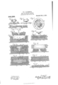
- Figure 1 shows a central cross-section Fig. 2. a side-view and Fig. 3. a top-view of such a knob concerned in my invention and which in form of an integral, hollow casting is produced by the means described in my invention.
- Fig. lSl1OWS the top or copemold in a vertical central cross-section.
- Fig. 5- is the core of the knob shown in side-elevation.
- Fig. 6 is the mold-core, a supplementary part of the lower, or drag-mold.
- Fig. 7- shows the lower part or drag of the mold which receives the complementary part above mentioned, both being shown each in a vertical, central cross-section.
- Fig. 8 shows a central cross-section Fig. 2. a side-view and Fig. 3. a top-view of such a knob concerned in my invention and which in form of an integral, hollow casting is produced by the means described in my invention.
- Fig. lSl1OWS the top or copemold in a vertical central
- FIG. 9 shows all these parts assembled to form the mold complete.
- Fig. 9 shows how the cope and drag-molds are produced, they together with the inserted patterns being shown in a central, vertical crosssection.
- Fig. 10- shows in side-elevation a part of the pattern whereby part of the mold-core shown in Fig. 6 is formed.
- Fig. 11 shows in a vertical, central cross-section this part in position together with additional, complementary parts required to form this mold-core.
- Fig. 12in central, vertical cross-sections illustrates the procedure whereby the mold- Speeifieation of Letters Patent.
- Fig. 18- shows in a vertical cross-section and at reduced scale how the cope and drag-molds may be produced in multiple by means of a match plate.
- Fig. 14- shows in a similar View means whereby the mold-core may be pr0- quizd in multiple.
- Fig. 9 is the pattern for molding the cope-mold 25
- 26 is the pattern for molding the drag-mold 27, these molds containing respectively the upper or outer part of the knob and the underside of its flange 20, together with the hub 22 and the print 28 for core 23.
- These two parts of the mold are prepared in the customary way in flasks 29 and 31, patterns 24 and 26, preferably combined in one piece, being first placed in one of the flasks, after which the other flask is superimposed and rammed, a moldingboard .32 being used and placed under the lower flask. As shown, the flasks are in a position reversed at this time against the position which they later occupy when the completed mold is set up for casting, see Figs.
- 34 is a base which contains the pattern for the upper or outer side of flange 20, the pattern 36 for the under side of the knob and its shank 21 being removably seated therein, it being centered by a pin 37, which is fitted to enter a socket in the lower pattern 35.
- a ring 38 is fitted on the upper side of base 34 to confine the sand while this mold core is formed. After that, pattern 36 is carefully lifted out and a plate 39 (see Fig. 12) is placed on top of ring 38.
- prues and pouring gates 10 are provided in the usual manner.
- pattern 36 is complementary to pattern 24 for forming the mold for the outside of the knob with parts of its shank, while core 23 forms the inside thereof.
- Pattern 35 is complementary to pattern 26 for forming the mold space for flange 20, the first forming the upper, or outer side and the other the under-side of the same.
- Mold 25 (see Fig. 8) is complementary to the upper side of the mold-core 33 and to the top of core 23, both being in line while mold 27 and the lower part of core 23 are complementary to the under-side and central space of this mold-core, meaning thereby the parts mentioned inclose the space into which the molten metal is received to cast the knob.
- any inscription on the outside of the knob as well as the graduations and figures on flange 20 are all accurately produced being contained, the first in the cope-mold and the other on the underside of mold-core 33, they being provided for on patterns 24 and 35 respectively.
- molds 25 and 26 in multiple, say 6 or 12
- a match-board 41 being used as shown in Fig. 13.
- the mold-cores 33 may also be produced in multiple and in numbers corresponding to those produced by match-board 41, by modifying the means shown in Figs. 10, 11, and 12 for forming a single mold-core.
- a board 42 is used of sufficient size to provide for patterns 35 in such numbers as is desired.
- a tray 43 takes the place of ring 38, the same resting on board %2 and having openings in its bottom to admit patterns It is not necessary to lift this block of mold-cores out of this tray, and they, together with this tray may be set into the drag-mold to which they are complementary, this latter being formed accordingly and in a manner substantially as shown in Fig. 13, to reserve the requisite space. As a matter of fact even in the case as first described where these mold-cores are formed singly, it would not be necessary to remove them from ring 38 provided of course the recess in the drag-mold is sufficiently large to receive both.
Landscapes
- Engineering & Computer Science (AREA)
- Mechanical Engineering (AREA)
- Dental Prosthetics (AREA)
Description
Patented Feb.1,1910.
UNITED STATES PATENT OFFICE.
WILLIAM T. BAUSMITI-I, 0F BELLEVUE, KENTUCKY, ASSIGNOR TO VICTOR SAFE & LOCK 00., OF CINCINNATI, OHIO, A CORPORATION OF OHIO.
MOLD FOR HOLLOW CASTING-S.
To all whom "it may concern:
Be it known that I, VILLIAM T. BAU- SMITH, a citizen of the United States, and residing at Bellevue, Campbell county, State of Kentucky, have invented a certain Mold for Hollow Castings of a Certain Shape; and I do declare the following to be a clear, full, and exact description of the invention, attention being called to the accompanying drawing, with the reference characters marked thereon, which forms also apart of this specification.
This invention relates to a mold for hollow castings of a shape similar to the knobs or handles used for the purpose of manipulating the combination locks of safes. These knobs are now made either solid, or if hollow, they are built up of several pieces connected to each other.
The object of my invention is to manufacture such knobs in one integral piece and to have them hollow to save metal.
The mold as hereinafter described and claimed and as illustrated in the accompanying drawing in which:
Figure 1. shows a central cross-section Fig. 2. a side-view and Fig. 3. a top-view of such a knob concerned in my invention and which in form of an integral, hollow casting is produced by the means described in my invention. Fig. lSl1OWS the top or copemold in a vertical central cross-section. Fig. 5-is the core of the knob shown in side-elevation. Fig. 6is the mold-core, a supplementary part of the lower, or drag-mold. Fig. 7-shows the lower part or drag of the mold which receives the complementary part above mentioned, both being shown each in a vertical, central cross-section. Fig. 8
shows all these parts assembled to form the mold complete. Fig. 9shows how the cope and drag-molds are produced, they together with the inserted patterns being shown in a central, vertical crosssection. Fig. 10- shows in side-elevation a part of the pattern whereby part of the mold-core shown in Fig. 6 is formed. Fig. 11shows in a vertical, central cross-section this part in position together with additional, complementary parts required to form this mold-core. Fig. 12in central, vertical cross-sections illustrates the procedure whereby the mold- Speeifieation of Letters Patent.
Application filed July 28, 1905.
Patented Feb. 1, 1910. Serial No. 271,592.
core is released from the parts whereby it has been formed, the latter being shown in reversed position below the reversed ring 38 from which it has been released and supported upon a plate 39. Fig. 18-shows in a vertical cross-section and at reduced scale how the cope and drag-molds may be produced in multiple by means of a match plate. Fig. 14-shows in a similar View means whereby the mold-core may be pr0- duced in multiple.
In the drawing 19 indicates the handle proper and '20 an annular flange which projects laterally from the shank 21 of the knob and usually at its outer, inclined'edge carries the graduations, marks and numerals constituting a dial provided and used to govern the rotation of the handle for setting a certain combination of the lock. 22 is a hub on the inner side of the handle whereby the same is mounted upon the lock spindle. As before stated the object of my invention is to produce such a combined knob and dial in form of an integral, hollow casting, a core 23, see Figs. 5 and 8, being used for this purpose which is prepared in a proper way in a customary core-box.
24, Fig. 9 is the pattern for molding the cope-mold 25, and 26 is the pattern for molding the drag-mold 27, these molds containing respectively the upper or outer part of the knob and the underside of its flange 20, together with the hub 22 and the print 28 for core 23. These two parts of the mold are prepared in the customary way in flasks 29 and 31, patterns 24 and 26, preferably combined in one piece, being first placed in one of the flasks, after which the other flask is superimposed and rammed, a moldingboard .32 being used and placed under the lower flask. As shown, the flasks are in a position reversed at this time against the position which they later occupy when the completed mold is set up for casting, see Figs. 9 and 8, although their particular arrangement at that time for filling them is not important. The division or parting of the molds so formed is at a point in line with the largest diameter of the knob. For molding the inner or under side of the same with its shank 21 and the upper or outer side of flange 20, I provide a mold-core 33,
the same being independently prepared outside of the mold in reversed position and by means shown in Figs. 10 and 11.. In these figures, 34: is a base which contains the pattern for the upper or outer side of flange 20, the pattern 36 for the under side of the knob and its shank 21 being removably seated therein, it being centered by a pin 37, which is fitted to enter a socket in the lower pattern 35. A ring 38 is fitted on the upper side of base 34 to confine the sand while this mold core is formed. After that, pattern 36 is carefully lifted out and a plate 39 (see Fig. 12) is placed on top of ring 38. This latter and base 34: are next reversed and base 34 is lifted off and finally ring 38 is raised off from plate 39, leaving the complete mold-core resting on said plate as shown in Fig. 12. Before proceeding further, this moldcore may be dried or baked. All parts of the mold are now completed as shown in Figs. 4, 5, 6 and 7 and ready to be assembled. For such purpose the drag-mold (Fig. 7) being in proper position on board 32, (see Fig. 8) the mold core 33 (Fig. 6) is set into the recess reserved for it, it being understood that the thickness of pattern 26 is such as to reserve the necessary space for this purpose, that is to receive the mold-core. This latter when so inserted completes the drag-mold of which it forms a complementary part. Core 23 (Fig. 5) is next set into its print 28, after which the cope-mold 25 (Fig. l) is set on top of the drag-mold, thus completing the mold as shown in (Fig. 8). Perfect fit and centering of the parts is insured by the usual ins and lugs on the outside of the flasks.
prues and pouring gates 10 are provided in the usual manner.
It will be noted that pattern 36 is complementary to pattern 24 for forming the mold for the outside of the knob with parts of its shank, while core 23 forms the inside thereof. Pattern 35 is complementary to pattern 26 for forming the mold space for flange 20, the first forming the upper, or outer side and the other the under-side of the same. Mold 25 (see Fig. 8) is complementary to the upper side of the mold-core 33 and to the top of core 23, both being in line while mold 27 and the lower part of core 23 are complementary to the under-side and central space of this mold-core, meaning thereby the parts mentioned inclose the space into which the molten metal is received to cast the knob. Any inscription on the outside of the knob as well as the graduations and figures on flange 20 are all accurately produced being contained, the first in the cope-mold and the other on the underside of mold-core 33, they being provided for on patterns 24 and 35 respectively. For producing molds 25 and 26 in multiple, say 6 or 12, molding by match-board is resorted to, a match-board 41 being used as shown in Fig. 13. The mold-cores 33 may also be produced in multiple and in numbers corresponding to those produced by match-board 41, by modifying the means shown in Figs. 10, 11, and 12 for forming a single mold-core. In place of molding-base 3a a board 42 is used of sufficient size to provide for patterns 35 in such numbers as is desired. A tray 43 takes the place of ring 38, the same resting on board %2 and having openings in its bottom to admit patterns It is not necessary to lift this block of mold-cores out of this tray, and they, together with this tray may be set into the drag-mold to which they are complementary, this latter being formed accordingly and in a manner substantially as shown in Fig. 13, to reserve the requisite space. As a matter of fact even in the case as first described where these mold-cores are formed singly, it would not be necessary to remove them from ring 38 provided of course the recess in the drag-mold is sufficiently large to receive both.
It will now be seen that I am enabled to produce by means of a two-part flask and one part-ing, a knob of a shape substantially as shown and which is hollow and provided with an integral flange, containing also in its face all the graduations, lines, numerals and characters which are required for the dial.
Having described my invention, 1 claim as new:
A two-flask, single-parted mold for casting in an integral piece, a hollow safe-knob with a circular flange having dial graduations and a hollow shank which combines both, the lower of the two flasks below the parting line containing the drag-mold which is provided with a cup-shaped recess, the bottom of which is pattern-formed and has also a central core-print, an independently, pattern-formed mold-core fitted to this recess in a manner that when in position its upper side is even with the upper side of the drag-mold and even with the upper edge of the lower flask, whereby these alined upper sides constitute the parting line of the mold, said mold-core being open in its center-portion and pattern-formed therein as well as on its under side which is complementary to the pattern-formed bottom of the recess in the drag-mold, it being spaced from said bottom to admit the metal for the flanged and graduated dial-member of the casting, a central core seated in the core-print mentioned from which it extends upwardly through the opening in the mold-core and above the same, it being spaced from the mold-core to which it is complementary the metal for the hollow shank and for the lower part of the knob being admitted between the two, the
upper of the two flasks containing the copemetal for the upper part of the hollow mold which is fitted to the drag-mold on the knob. 10 parting line formed by the alined upper In testimony whereof, I hereunto aflix my sides of said drag-mold and the mold-core signature in the presence of two witnesses.
therein, and pattern-formed on its underside VILLIAM T. BAUSMITH. complementary to the upper part of the cen- Witnesses: tral core which projects above the mold-core C. SPENGEL,
and from which it is spaced to admit the C. MEYER.
Priority Applications (1)
| Application Number | Priority Date | Filing Date | Title |
|---|---|---|---|
| US27159205A US948288A (en) | 1905-07-28 | 1905-07-28 | Mold for hollow castings. |
Applications Claiming Priority (1)
| Application Number | Priority Date | Filing Date | Title |
|---|---|---|---|
| US27159205A US948288A (en) | 1905-07-28 | 1905-07-28 | Mold for hollow castings. |
Publications (1)
| Publication Number | Publication Date |
|---|---|
| US948288A true US948288A (en) | 1910-02-01 |
Family
ID=3016704
Family Applications (1)
| Application Number | Title | Priority Date | Filing Date |
|---|---|---|---|
| US27159205A Expired - Lifetime US948288A (en) | 1905-07-28 | 1905-07-28 | Mold for hollow castings. |
Country Status (1)
| Country | Link |
|---|---|
| US (1) | US948288A (en) |
Cited By (1)
| Publication number | Priority date | Publication date | Assignee | Title |
|---|---|---|---|---|
| WO2007126981A3 (en) * | 2006-03-28 | 2008-08-21 | Gorman Rupp Co | Impeller |
-
1905
- 1905-07-28 US US27159205A patent/US948288A/en not_active Expired - Lifetime
Cited By (3)
| Publication number | Priority date | Publication date | Assignee | Title |
|---|---|---|---|---|
| WO2007126981A3 (en) * | 2006-03-28 | 2008-08-21 | Gorman Rupp Co | Impeller |
| US20100239417A1 (en) * | 2006-03-28 | 2010-09-23 | Scott Thomas M | Impeller |
| US8025479B2 (en) | 2006-03-28 | 2011-09-27 | The Gorman-Rupp Company | Impeller |
Similar Documents
| Publication | Publication Date | Title |
|---|---|---|
| US2789331A (en) | Method and apparatus for making molds useful in casting | |
| US1657444A (en) | Process of and means for preparing molds | |
| US3463221A (en) | Modular sand mold | |
| US9095A (en) | Improvement in patterns for metal hubs | |
| US1281946A (en) | Casting apparatus. | |
| US1207495A (en) | Art of casting metals. | |
| US195843A (en) | Improvement in sand-molding apparatus for casting metal articles | |
| US971045A (en) | Mold for hollow articles. | |
| US30525A (en) | Improvement in molding cast-iron wheels | |
| US670613A (en) | Drag-pattern. | |
| US701105A (en) | Flask for sand molds. | |
| US1075290A (en) | Mold for hollow articles. | |
| US1333502A (en) | Metal mold and process of making the same | |
| US2029499A (en) | Metal mold | |
| US38243A (en) | Improvement in flasks for founders | |
| US1862975A (en) | Pipe casting apparatus | |
| US1537299A (en) | Jacket for sand molds | |
| US976897A (en) | Making master-plates. | |
| US57644A (en) | Improved machine for making cast-steel castings | |
| US1812491A (en) | Core for metal casting molds | |
| US256410A (en) | Mold for casting car-wheels | |
| US981904A (en) | Mold for casting chilled car-wheels or other circular objects. | |
| US918328A (en) | Mold for hollow articles. | |
| US37272A (en) | Improvement in molding chilled-iron projectiles | |
| US219412A (en) | Improvement in apparatus for molding and casting heaters for air-engines |