US9482487B2 - Paraclip adapter - Google Patents
Paraclip adapter Download PDFInfo
- Publication number
- US9482487B2 US9482487B2 US14/945,816 US201514945816A US9482487B2 US 9482487 B2 US9482487 B2 US 9482487B2 US 201514945816 A US201514945816 A US 201514945816A US 9482487 B2 US9482487 B2 US 9482487B2
- Authority
- US
- United States
- Prior art keywords
- configuration
- adapter
- post portion
- socket
- post
- Prior art date
- Legal status (The legal status is an assumption and is not a legal conclusion. Google has not performed a legal analysis and makes no representation as to the accuracy of the status listed.)
- Active
Links
Images


Classifications
-
- F—MECHANICAL ENGINEERING; LIGHTING; HEATING; WEAPONS; BLASTING
- F41—WEAPONS
- F41C—SMALLARMS, e.g. PISTOLS, RIFLES; ACCESSORIES THEREFOR
- F41C33/00—Means for wearing or carrying smallarms
- F41C33/006—Clips, hooks or the like, for carrying the weight of smallarms
- F41C33/007—Clips, hooks or the like, for carrying the weight of smallarms for long firearms, e.g. rifles
-
- F—MECHANICAL ENGINEERING; LIGHTING; HEATING; WEAPONS; BLASTING
- F41—WEAPONS
- F41C—SMALLARMS, e.g. PISTOLS, RIFLES; ACCESSORIES THEREFOR
- F41C23/00—Butts; Butt plates; Stocks
- F41C23/02—Attachment of slings
-
- F—MECHANICAL ENGINEERING; LIGHTING; HEATING; WEAPONS; BLASTING
- F41—WEAPONS
- F41C—SMALLARMS, e.g. PISTOLS, RIFLES; ACCESSORIES THEREFOR
- F41C33/00—Means for wearing or carrying smallarms
- F41C33/006—Clips, hooks or the like, for carrying the weight of smallarms
-
- F—MECHANICAL ENGINEERING; LIGHTING; HEATING; WEAPONS; BLASTING
- F16—ENGINEERING ELEMENTS AND UNITS; GENERAL MEASURES FOR PRODUCING AND MAINTAINING EFFECTIVE FUNCTIONING OF MACHINES OR INSTALLATIONS; THERMAL INSULATION IN GENERAL
- F16B—DEVICES FOR FASTENING OR SECURING CONSTRUCTIONAL ELEMENTS OR MACHINE PARTS TOGETHER, e.g. NAILS, BOLTS, CIRCLIPS, CLAMPS, CLIPS OR WEDGES; JOINTS OR JOINTING
- F16B13/00—Dowels or other devices fastened in walls or the like by inserting them in holes made therein for that purpose
- F16B13/04—Dowels or other devices fastened in walls or the like by inserting them in holes made therein for that purpose with parts gripping in the hole or behind the reverse side of the wall after inserting from the front
- F16B13/08—Dowels or other devices fastened in walls or the like by inserting them in holes made therein for that purpose with parts gripping in the hole or behind the reverse side of the wall after inserting from the front with separate or non-separate gripping parts moved into their final position in relation to the body of the device without further manual operation
- F16B13/0891—Dowels or other devices fastened in walls or the like by inserting them in holes made therein for that purpose with parts gripping in the hole or behind the reverse side of the wall after inserting from the front with separate or non-separate gripping parts moved into their final position in relation to the body of the device without further manual operation with a locking element, e.g. wedge, key or ball moving along an inclined surface of the dowel body
-
- Y—GENERAL TAGGING OF NEW TECHNOLOGICAL DEVELOPMENTS; GENERAL TAGGING OF CROSS-SECTIONAL TECHNOLOGIES SPANNING OVER SEVERAL SECTIONS OF THE IPC; TECHNICAL SUBJECTS COVERED BY FORMER USPC CROSS-REFERENCE ART COLLECTIONS [XRACs] AND DIGESTS
- Y10—TECHNICAL SUBJECTS COVERED BY FORMER USPC
- Y10T—TECHNICAL SUBJECTS COVERED BY FORMER US CLASSIFICATION
- Y10T29/00—Metal working
- Y10T29/49—Method of mechanical manufacture
- Y10T29/49716—Converting
Definitions
- the present disclosure relates generally to firearms accessories.
- the present disclosure relates to systems, methods and apparatuses for quickly attaching and detaching an adapter to a firearm configured for coupling to a sling.
- Slings are regularly used with firearms to allow for a convenient method of carry and for weapon retention in dynamic environments.
- Traditional slings mount onto the bottom of a weapon at two points, fore and aft, allowing for suitable carry over long distances and may be used as a steadying aid to improve weapon accuracy. While it offers the user the ability to carry the weapon comfortably over the shoulder or securely across the back, the traditional, bottom-mounted 2-point sling hinders weapon usage in dynamic combat environments since the weapon is stowed in a non-useable orientation.
- 2-point slings may be used in combat as an accuracy aid by being wrapped around the arm or other techniques, this encumbers the user through entanglement in the sling itself and is mostly useful only for long-range engagements.
- sling swivels have been used to secure slings to the weapon. These swivels have taken many forms but they all have similar characteristics: namely, they are rotatable (swivel) about a point and are usually an elongated loop through which sling material may be threaded. They have been positioned on either side of the weapon, so that the sling may be said to be mounted on either side, or on the upper and lower surfaces of the weapon, so that the sling may be said to be mounted along the weapon, or a combination thereof.
- the quick detach or “QD” interface was thus developed in order to enable rapid removal of a sling from a firearm.
- the QD interface includes a “QD socket” including a female portion of the interface and a QD body including a male portion of the interface.
- the QD socket (sometimes referred to as a “swivel socket”) typically includes an axial cavity sometimes having an annular ring into which a portion of the QD body can selectively couple to.
- the QD body typically includes some type of loop or bail for either threading a sling through or for coupling to via a clip such as the snap clip illustrated in U.S.
- the QD body also typically includes a “connection post” that fits into and interfaces with the axial cavity of the QD socket.
- many QD bodies feature an internal spring loaded plunger that biases a plurality of ball bearings through the QD connection post. The ball bearings then interface with a ridge in a QD socket and hold the QD body in place. When desired, the user depresses the plunger and the bias on the ball bearings is removed, allowing them to roll into the casing and thereby allowing the QD body to be removed from the QD socket.
- Some exemplary QD sockets include the EZ CARBINE QD SWIVEL ATTACHMENT POINT from DANIEL DEFENSE, and the RAIL MOUNT QD SLING SWIVEL from DANIEL DEFENSE, to name a few.
- Some exemplary QD bodies include the QUICK-DETACH SLING SWIVEL from VLTOR WEAPON SYSTEMS, the QD SLING SWIVEL from DAMAGE INDUSTRIES, the QD SWIVEL from DANIEL DEFENSE, and the HEAVY DUTY FLUSH BUTTON SWIVEL from MI, to name a few.
- the present invention can provide a system and method for modifying a QD connection.
- the present invention can include an adapter for a QD socket.
- the adapter has a first post portion having a longitudinal axis, a loop, and a first contact tab shaped to interface with a QD socket, and a second post portion having a second contact tab shaped to interface with a QD socket.
- the second post portion is coupled to the first post portion and movable between a first configuration defining a first transverse distance between the first and second contact tabs and a second configuration defining a second transverse distance between the first and second contact tabs.
- the first transverse distance is greater than the second transverse distance.
- Another exemplary embodiment includes a method of modifying a quick disconnect attachment.
- the method includes providing an adapter assembly having a plurality of contact tabs, the plurality of contact tabs movable between a first configuration having a first transverse distance between the plurality of contact tabs and a second configuration having a second transverse distance between the plurality of contact tabs, the first transverse distance greater than the second transverse distance.
- the method further includes loosening the adapter assembly to cause the adapter assembly to move from the first configuration to the second configuration.
- the method further includes inserting a distal portion of the adapter into a QD socket, and orienting a loop on the adapter assembly to a desired position.
- the method further includes tightening the adapter assembly to cause the adapter assembly to move from the second configuration to an engagement configuration wherein the first and second contact tabs engage the QD socket to maintain the adapter assembly attached to the QD socket in a semi-permanent manner.
- Another exemplary embodiment includes an adapter for a QD socket having a connection post having a plurality of contact tabs movable relative to each other between a first configuration and a second configuration.
- the first configuration defines a maximum effective outer diameter of the connection post
- the second configuration defines a minimum effective outer diameter of the connection post.
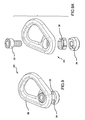
- FIG. 1 is an isometric view of a wedging QD adapter
- FIG. 2 is a front view of the adapter in FIG. 1 ;
- FIG. 3 is a side view of the adapter in FIG. 1 ;
- FIG. 4A is a rear view of the adapter in FIG. 1 ;
- FIG. 4B is a rear view of the upper portion of the adapter in FIG. 1 ;
- FIG. 5A is a top view of the adapter in FIG. 1 ;
- FIG. 5B is a top view of the upper portion of the adapter in FIG. 1 ;
- FIG. 6A is a bottom view of the adapter in FIG. 1 ;
- FIG. 6B is a bottom view of an alternative adapter having an alternative tab
- FIG. 6C is a bottom view of another alternative adapter having another alternative tab
- FIG. 7 is an isometric view of the upper portion of the adapter in FIG. 1 ;
- FIG. 8 is an isometric view of the lower portion of the adapter in FIG. 1 ;
- FIG. 9 is an isometric view of another alternative adapter having a wedging ring
- FIG. 9A is an isometric exploded view of the alternative adapter in FIG. 9 ;
- FIG. 9B is a rear exploded view of the alternative adapter in FIG. 9 ;
- FIG. 10 is an isometric view of another alternative adapter having another wedging feature
- FIG. 10A is an exploded isometric view of the upper portion and lower portion of the another alternative adapter in FIG. 10 ;
- FIG. 10B is an exploded rear view of the upper portion and lower portion of the another alternative adapter in FIG. 10 ;
- FIG. 11 is an isometric view of another alternative adapter having a wedging prong
- FIG. 11A is an exploded isometric view of the upper portion and lower portion of the another alternative adapter in FIG. 11 ;
- FIG. 11B is an exploded front view of the upper portion and lower portion of the another alternative adapter in FIG. 11 ;
- FIG. 12 is an isometric view of an exemplary QD socket used with an embodiment of the adapter.
- FIG. 13 is a flowchart of one embodiment of a method.
- the present disclosure relates generally to firearms accessories.
- the present disclosure relates to systems, methods and apparatuses for quickly attaching and detaching an adapter to a firearm configured for coupling to a sling.
- the herein disclosed adapter includes various attachment means used to fix the adapter to a QD socket (either allowing some, minimal, or no rotation depending on the QD socket) in a semi-permanent manner.
- a wedged design is used (see FIGS. 1-8 ) wherein turning of a screw that passes through the adapter changes an effective outer diameter of a connection post of the adapter by pulling an upper and lower portion of the connection post together vertically and forcing them apart laterally.
- the effective outer diameter can be greater than an inner diameter of the QD socket.
- FIG. 1 is an isometric view of a novel wedging adapter according to one embodiment of this disclosure.
- the illustrated wedging QD body 100 includes a loop that can be clipped into via a sling.
- the QD body 100 also includes a connection post 108 affixed to the connection post 108 and including an upper portion 102 of the connection post 108 and a lower portion 104 of the connection post 108 .
- the adapter 100 can be tightened and coupled into a QD socket by tightening a screw 110 (although illustrated as a hex screw, other types of screws can also be used).
- the screw 110 passes generally longitudinally through an elongate slot in the upper portion 102 and screws into a threaded opening in the lower portion 104 .
- the screw 110 tightens, the upper portion 102 and the lower portion 104 are drawn together. However, when the two portions 102 , 104 meet at an angled interface 112 , continued rotation of the screw 110 continues to apply vertical force between the two portions 102 , 104 causing the upper and lower portions 102 , 104 to move laterally relative to each other and thereby causing an increase in an effective outer diameter of the connection post 108 .
- the upper portion 102 would move out of the page and to the left of the page while the lower portion 104 would move into the page and to the right of the page.
- the direction of lateral movement can be controlled by an optional guide ridge 114 in the lower portion 104 that interfaces with an optional guide valley 116 in the upper portion 102 .
- the optional guide ridge 114 and the optional guide valley 116 can be shaped and sized so as to fit into each other.
- the guide ridge 114 and the guide valley 116 are arranged parallel to a plane that passes through the adapter from a front to a back and from a top to a bottom of the adapter 100 .
- the guide ridge 114 has a seat 114 a that has an abutting surface perpendicular to a longitudinal axis of the connection post and a nesting seat 114 b having an abutting surface parallel to the longitudinal axis.
- other planes for lateral movement can be used and thereby effect different directions of lateral movement between the upper and lower portions 102 , 104 .
- the connection post 108 includes a tab 118 on a front side (part of the upper portion 102 ) and a tab 120 on a back side (part of the lower portion 104 ). As the upper and lower portions 102 , 104 move laterally relative to each other, the tabs 118 , 120 move laterally apart and thus increase an effective outer diameter of the connection post 108 and hence enable the tabs 118 , 120 to lock into an annular groove in a QD socket.
- a QD socket can include a discontinuous annular groove or other openings in a side of the QD socket that the tabs 118 , 120 can fit into and thereby prevent swiveling of the adapter, or at least prevent more than a set amount of swiveling.
- the screw 110 passes through an elongated slot 130 in the upper portion 102 as seen in FIGS. 5B and 7 .
- the elongated slot 130 enables the screw 110 to move laterally relative to the upper portion 102 . Since the screw 110 couples to an internal threading of the lower portion 104 , the screw 110 does not move laterally relative to the lower portion 104 . However, as the screw 110 is tightened and loosened it moves laterally relative to the upper portion 104 and thus the elongated slot 130 allows this lateral movement.
- the longer dimension of the elongated slot 130 can be arranged parallel to the axis of lateral movement of the upper and lower portions 102 , 104 relative to each other.
- the effective outer diameter of the adapter 100 has been discussed throughout this disclosure.
- the effective outer diameter is a maximum diameter of portions of the connection post 108 that interface with a QD socket as illustrated in FIG. 3 .
- FIG. 3 shows the upper and lower portions 102 , 104 when the screw 110 is relatively loose, and hence the effective outer diameter of the connection post 108 is near a minimum.
- the lower portion 104 would move to the right and the upper portion 102 would move to the left, relative to each other on the page.
- this causes the effective outer diameter of the connection post 108 to increase and in this way a tight interface can be formed between the connection post 108 and a QD socket.
- FIG. 4A illustrates a back view of the adapter 100 in FIG. 3 , including the tab 120 for interfacing with a QD socket, and a guide mechanism 117 .
- the guide mechanism 117 is shown with a guide ridge 114 in the lower portion 104 interfacing with a guide valley 116 in the upper portion 102 , to limit rotation of the upper portion 102 relative to the lower portion 104 .
- FIG. 4B illustrates a back view of the upper portion 102 and guide valley 116 therein.
- FIG. 7 and 8 illustrate isometric views of the features in further detail, including an optional deflashing surface 115 , wherein excess material has been removed after a molding operation.
- the assembly 100 may include a deflashing surface 115 , depending on the manufacturing method chosen, the surface may be absent in some embodiments.
- the adapter may have a travel stop 103 , 109 .
- the travel stop 103 has a first contact surface 105 in a first post portion, which may be the upper portion 102 , and the first contact surface 105 is perpendicular to the longitudinal axis of the first post portion.
- the travel stop 103 also has a second contact surface 107 in the first post portion that is parallel to the longitudinal axis.
- the first contact surface 105 defines the first configuration and the second contact surface 107 defines the second configuration.
- the angled interface 112 can have an angle of approximately 30° when measured relative to a horizontal plane passing through front, rear, and sides of the adapter 100 (i.e., parallel to the page in FIG. 5A ). However, other angles are also envisioned and those between 15° and 45° may be preferred where greater lateral forces and/or lateral movement of the upper and lower portions 102 , 104 relative to each other are desired.
- FIG. 2 it is seen that the tab 118 has a semi-circular profile as viewed from the front. While this can be effective for certain applications and certain QD sockets, it is not required, and other shapes and sizes of tabs 118 and 120 can be implemented.
- FIGS. 6B-6C illustrate some other embodiments of the tab 118 .
- a common feature is that the tab 118 fits within an imaginary semicircle that corresponds to, or is slightly greater than an inner diameter of a QD socket (e.g., a 0.375′′ diameter semi-circle).
- the lower portion 104 is not perfectly circular.
- a front half of the lower portion 104 has a circular shape while the rear half has an elliptical or offset circular shape.
- the tab 120 should fit into an imaginary circle that mimics the radius of the front half and then extends this radius to the back half. This radius can be equal to or wider than an inner radius of a QD socket.
- FIGS. 6B-6C have been illustrated with exaggerated scales in order to more clearly show the elliptical or offset circular nature of the rear half (or rear portion) of the lower portion 104 .
- the adapter 100 can exclude one or both of the tabs 118 , 120 .
- the QD socket to which the adapter 100 is to be coupled may not have an annular groove for the tabs 118 , 120 to engage.
- a screw 110 has been illustrated and described as the mechanism to apply force between the upper and lower portions 102 , 104 and thereby expand or decrease the effective outer diameter of the connection post 108 interfacing with a QD socket
- other means can be used such as a screw passing through slots in both the upper and lower portions 102 , 104 (no threading) and a washer or nut below the lower portion 104 .
- This is just one non-limiting example of other means that can be used to apply vertical force between the upper and lower portions 102 , 104 .
- FIG. 6A is a bottom plan view of an alternative embodiment of a wedging adapter having an alternative shape to the tab 120 on the lower portion 104 .
- FIG. 6B is a bottom plan view of an alternative embodiment of a wedging adapter having another alternative shape to the tab 120 on the lower portion 104 . From these two examples it should be apparent that various shapes and sizes of the tab 120 can be implemented as long as the shape and size of the tab fits within a circle having an imaginary circle congruent with a front half of the lower portion 104 and having a diameter equal to or greater than an inner diameter of a QD socket to be interfaced with.
- FIGS. 9, 9A, and 9B another embodiment of an adapter assembly 200 is now described. While the adapter assembly 200 now described has the general functionality of the embodiment shown in FIG. 1 , the features and manner of operation is slightly different.
- the assembly 200 has a screw 210 coupling a loop 206 to a lower portion 204 , with an interface ring 232 therebetween.
- the interface ring 232 has one or more tabs 220 that may interface with a QD socket.
- a loop 206 may be provided as an attachment interface.
- tightening the screw 210 causes the upper portion 202 of the assembly 200 to move closer to the lower portion 204 .
- angled surfaces 234 , 236 in the upper and lower portions 202 , 204 respectively cause the interface ring 232 to expand outwardly, thereby increasing the effective overall diameter of the interface ring 232 .
- the interface ring 232 may be manufactured of a material that is more elastic than the upper and lower portions 202 , 204 .
- FIGS. 10, 10A, and 10B a third embodiment of the assembly 300 is now described.
- the assembly 300 is similar to assembly 200 , with a loop 306 , an upper portion 302 , a lower portion 304 , and a screw 310 attaching the upper and lower portions 302 , 304 .
- tightening the screw 310 causes the upper portion 302 to approach the lower portion 304 .
- one or more angled interfaces between the upper and lower portions 302 , 304 causes the upper portion 302 to expand.
- the upper portion 302 has one or more tabs 320 that expand with the upper portion thereby increasing the overall effective diameter of the upper portion 302 to interface with a QD socket.
- a guide ridge 314 and a guide valley 316 may further be included, so as to limit relative rotation between the upper and lower portions 302 , 304 .
- FIGS. 10-10B Although illustrated in FIGS. 10-10B as having an upper portion 302 that expands, it should be understood that the features and functionality may be reversed, such that the lower portion 304 expands as the upper and lower portions 302 , 304 approach one another, to cause an effective overall diameter to be increased for interfacing with a QD socket.
- the assembly 400 has an attachment interface 406 attached to an upper portion 402 which is, in turn, coupled to a lower portion 404 using a screw 410 .
- the lower portion 404 has one or more tabs 420 that are caused to expand as the screw 410 is tightened.
- One or more of the tabs 420 may have an upper region 434 for interfacing with an angled surface 436 in the upper portion 402 to aide in expansion. As the tabs 420 are expanded, they increase the overall effective diameter of the adapter 400 for interfacing with a QD socket.
- the upper region 434 of the tabs 420 may interface with a lip in a QD socket.
- the assembly 400 may also have a guide mechanism having a guide ridge 414 and a guide valley 416 in the upper and lower portions 402 , 404 respectively, so as to prevent rotation of the upper portion 402 relative to the lower portion 404 .
- the QD socket 500 generally has an interior groove 502 into which tabs, such as tabs 118 , 120 , 220 , 320 , 420 may expand or move, so as to engage the QD socket 500 in a semi-permanent manner, that is, until the assembly 100 , 200 , 300 , 400 is loosened and removed manually.
- tabs such as tabs 118 , 120 , 220 , 320 , 420 may expand or move, so as to engage the QD socket 500 in a semi-permanent manner, that is, until the assembly 100 , 200 , 300 , 400 is loosened and removed manually.
- the method 600 comprises providing 602 an adapter assembly having a plurality of tabs, the plurality of tabs movable between a first configuration having a first transverse distance between the plurality of tabs and a second configuration having a second transverse distance between the plurality of tabs, the first transverse distance greater than the second transverse distance.
- the method 600 further includes loosening 604 the adapter assembly to allow the adapter assembly to move from the first configuration to the second configuration.
- the method 600 further includes inserting 606 a distal portion of the adapter into a quick disconnect (QD) socket.
- QD quick disconnect
- the method 600 further includes orienting 608 an accessory attachment interface on the adapter assembly to a desired position.
- the accessory attachment interface is a loop.
- the method 600 further includes tightening 610 the adapter assembly to cause the adapter assembly to move from the second configuration to an engagement configuration wherein the first and second tabs engage the QD socket to selectively couple the adapter assembly to the QD socket.
- the method 600 may include limiting rotation of a second post portion of the adapter assembly relative to a first post portion of the adapter assembly and/or limiting the second post portion to travel between the first configuration and the second configuration.
- the method 600 may include causing a first seat in the first post portion to contact a perpendicular contact surface in the first configuration, and causing a second seat in the first post portion to contact a parallel contact surface in the second configuration.
- the method 600 may include causing a first contact surface in the first post portion to contact a first contact surface in the second post portion in the first configuration, the first contact surface in the second post portion perpendicular to a longitudinal axis of the second post portion.
- the method 600 may also include causing a second contact surface in the first post portion to contact a second contact surface in the second post portion in the second configuration, the second contact surface in the second post portion parallel to the longitudinal axis of the second post portion. See, for example, the first contact surface 105 in FIG. 7 , the first contact surface 109 in FIG. 8 , the second contact surface(s) 107 in FIG. 7 , and the second contact surface(s) 111 in FIG. 8 .
- the method 600 may include adjusting a fastener to cause the adapter assembly to move between the first configuration and the second configuration and/or causing the plurality of tabs to interface with one of a continuous annular groove in a QD socket, a discontinuous annular groove in a QD socket, and a plurality of openings in a QD socket.
- loosening 604 includes causing transverse movement of a first portion of the adapter assembly relative to a second portion of the adapter assembly, thereby narrowing an effective outer diameter of the distal portion of the adapter assembly
- tightening 610 includes causing transverse movement of the first portion relative to the second portion, thereby widening an effective outer diameter of the distal portion of the adapter assembly.
- the method 600 may be practiced using one or more of the adapter assemblies 100 , 200 , 300 , 400 described with reference to FIGS. 1-12 .
Landscapes
- Engineering & Computer Science (AREA)
- General Engineering & Computer Science (AREA)
- Clamps And Clips (AREA)
Abstract
Description
Claims (21)
Priority Applications (3)
| Application Number | Priority Date | Filing Date | Title |
|---|---|---|---|
| US14/945,816 US9482487B2 (en) | 2014-01-10 | 2015-11-19 | Paraclip adapter |
| US15/284,249 US9921029B2 (en) | 2014-01-10 | 2016-10-03 | Connector |
| US15/919,623 US10371482B2 (en) | 2014-01-10 | 2018-03-13 | Connector |
Applications Claiming Priority (3)
| Application Number | Priority Date | Filing Date | Title |
|---|---|---|---|
| US201461926195P | 2014-01-10 | 2014-01-10 | |
| US14/581,544 US9243866B2 (en) | 2014-01-10 | 2014-12-23 | Paraclip adapter |
| US14/945,816 US9482487B2 (en) | 2014-01-10 | 2015-11-19 | Paraclip adapter |
Related Parent Applications (3)
| Application Number | Title | Priority Date | Filing Date |
|---|---|---|---|
| US14/581,544 Continuation US9243866B2 (en) | 2014-01-10 | 2014-12-23 | Paraclip adapter |
| US14/658,171 Continuation-In-Part US9239210B2 (en) | 2014-01-10 | 2015-03-14 | Firearm accessory mounting interface |
| US15/284,249 Continuation US9921029B2 (en) | 2014-01-10 | 2016-10-03 | Connector |
Related Child Applications (2)
| Application Number | Title | Priority Date | Filing Date |
|---|---|---|---|
| US14/964,859 Continuation-In-Part US9523554B2 (en) | 2014-01-10 | 2015-12-10 | Firearm accessory mounting interface |
| US15/284,249 Continuation-In-Part US9921029B2 (en) | 2014-01-10 | 2016-10-03 | Connector |
Publications (2)
| Publication Number | Publication Date |
|---|---|
| US20160069638A1 US20160069638A1 (en) | 2016-03-10 |
| US9482487B2 true US9482487B2 (en) | 2016-11-01 |
Family
ID=53521089
Family Applications (2)
| Application Number | Title | Priority Date | Filing Date |
|---|---|---|---|
| US14/581,544 Active US9243866B2 (en) | 2014-01-10 | 2014-12-23 | Paraclip adapter |
| US14/945,816 Active US9482487B2 (en) | 2014-01-10 | 2015-11-19 | Paraclip adapter |
Family Applications Before (1)
| Application Number | Title | Priority Date | Filing Date |
|---|---|---|---|
| US14/581,544 Active US9243866B2 (en) | 2014-01-10 | 2014-12-23 | Paraclip adapter |
Country Status (1)
| Country | Link |
|---|---|
| US (2) | US9243866B2 (en) |
Cited By (3)
| Publication number | Priority date | Publication date | Assignee | Title |
|---|---|---|---|---|
| US10260841B2 (en) | 2016-10-20 | 2019-04-16 | Bravo Company Mfg, Inc. | Firearm accessory mounting system |
| US10724569B2 (en) | 2018-04-21 | 2020-07-28 | Maxim Defense Industries, LLC | Universal interface system, fastener apparatus and accessory rail system |
| USD1004033S1 (en) | 2020-01-20 | 2023-11-07 | Sagi Faifer | Handguard for a gun |
Families Citing this family (6)
| Publication number | Priority date | Publication date | Assignee | Title |
|---|---|---|---|---|
| US20170314888A1 (en) * | 2016-04-29 | 2017-11-02 | Falcon Operations Group | Firearm sling attachment device |
| USD813972S1 (en) * | 2016-11-04 | 2018-03-27 | Phase 5 Weapon Systems Inc. | End plate for a firearm |
| USD859959S1 (en) * | 2017-10-09 | 2019-09-17 | Lawrence M. Sawyer | Sling keeper comprised of a handle, a nut, and a holder |
| USD994069S1 (en) * | 2019-11-25 | 2023-08-01 | Glock Technology Gmbh | End plate sling adapter for firearm stock |
| USD917001S1 (en) * | 2020-01-23 | 2021-04-20 | RailScales LLC | Sling mount |
| US12140171B2 (en) * | 2020-05-01 | 2024-11-12 | John Robert McPhee | Movement-free quick detach latch |
Citations (15)
| Publication number | Priority date | Publication date | Assignee | Title |
|---|---|---|---|---|
| US2771699A (en) * | 1953-08-24 | 1956-11-27 | George L Herter | Quick detachable gun sling swivel |
| US3273444A (en) * | 1964-03-06 | 1966-09-20 | Dow Chemical Co | Expandable dowel |
| US3799027A (en) * | 1972-04-03 | 1974-03-26 | Illinois Tool Works | Anchor bolt |
| US4464076A (en) * | 1981-06-29 | 1984-08-07 | Hilti Aktiengesellschaft | Expansion dowel assembly |
| US4605350A (en) * | 1981-05-06 | 1986-08-12 | Izak Chater | Expansion shell |
| US4859118A (en) * | 1988-06-21 | 1989-08-22 | Birmingham Bolt Company, Inc. | Mine roof support anchor and process for installing the same |
| US20050183380A1 (en) * | 2002-02-21 | 2005-08-25 | Yoshinori Sato | Post-construction anchor, and drill bit for drilling prepared holes therefor |
| USD679580S1 (en) | 2011-08-26 | 2013-04-09 | Magpul Industries Corporation | Snap clip |
| US8429843B2 (en) | 2011-04-28 | 2013-04-30 | Leapers, Inc. | Foregrip |
| US8500358B1 (en) | 2006-08-01 | 2013-08-06 | Torque Fitness, Llc | Quick disconnect coupling |
| US8544153B2 (en) | 2011-09-09 | 2013-10-01 | Magpul Industries Corp | Lockable snap-clip fastener |
| US8596701B2 (en) | 2011-06-02 | 2013-12-03 | Mjt Holdings Llc | Anchor hoist ring assembly |
| US20140116057A1 (en) | 2012-10-26 | 2014-05-01 | United Technologies Corporation | Push-lock pin |
| US8821061B2 (en) | 2012-06-13 | 2014-09-02 | Pivot Point, Incorporated | Forward locking pull pin |
| US8832986B2 (en) * | 2012-05-16 | 2014-09-16 | Magpul Industries Corp. | Quick detach sling swivel |
Family Cites Families (15)
| Publication number | Priority date | Publication date | Assignee | Title |
|---|---|---|---|---|
| US317448A (en) * | 1885-05-05 | Feedeeic h | ||
| US1316640A (en) * | 1919-09-23 | Expansion-bom | ||
| US1964427A (en) * | 1933-09-29 | 1934-06-26 | Ohio Brass Co | Expansion bolt |
| US1993749A (en) * | 1934-03-03 | 1935-03-12 | Newhall Henry B Corp | Bolt anchor |
| US2078010A (en) * | 1934-03-06 | 1937-04-20 | Meepos Max | Detachable flush swivel for gun slings |
| US2116618A (en) * | 1936-05-01 | 1938-05-10 | Winchester Repeating Arms Co | Firearm |
| US2480662A (en) * | 1948-06-21 | 1949-08-30 | Preston V Mckinzie | Detachable gun sling swivel |
| US3478641A (en) * | 1967-02-07 | 1969-11-18 | Dohmeier Hans Otto | Anchor or roof bolts and the like |
| US3844194A (en) * | 1973-02-14 | 1974-10-29 | Illinois Tool Works | Wedge anchor device |
| US4571872A (en) * | 1984-09-06 | 1986-02-25 | Johnson David A | Device for attaching a front sling-receiving loop to a weapon |
| US5352066A (en) * | 1991-11-26 | 1994-10-04 | The Eastern Company | Mine roof/bolt anchor assembly and method of installation thereof |
| US7654027B1 (en) * | 2007-01-11 | 2010-02-02 | Grovtec U S, Inc. | Twist-lock sling swivel |
| US8282318B2 (en) * | 2009-03-02 | 2012-10-09 | Robertson Jr Roy Lee | Roof bolt anchor with camming element |
| US8516732B2 (en) * | 2010-12-14 | 2013-08-27 | Blue Force Gear, Inc. | Detachable swivel and associated mount |
| US8832985B2 (en) * | 2012-05-16 | 2014-09-16 | 1 Pin, LLC | Attachment assembly for firearm sling |
-
2014
- 2014-12-23 US US14/581,544 patent/US9243866B2/en active Active
-
2015
- 2015-11-19 US US14/945,816 patent/US9482487B2/en active Active
Patent Citations (15)
| Publication number | Priority date | Publication date | Assignee | Title |
|---|---|---|---|---|
| US2771699A (en) * | 1953-08-24 | 1956-11-27 | George L Herter | Quick detachable gun sling swivel |
| US3273444A (en) * | 1964-03-06 | 1966-09-20 | Dow Chemical Co | Expandable dowel |
| US3799027A (en) * | 1972-04-03 | 1974-03-26 | Illinois Tool Works | Anchor bolt |
| US4605350A (en) * | 1981-05-06 | 1986-08-12 | Izak Chater | Expansion shell |
| US4464076A (en) * | 1981-06-29 | 1984-08-07 | Hilti Aktiengesellschaft | Expansion dowel assembly |
| US4859118A (en) * | 1988-06-21 | 1989-08-22 | Birmingham Bolt Company, Inc. | Mine roof support anchor and process for installing the same |
| US20050183380A1 (en) * | 2002-02-21 | 2005-08-25 | Yoshinori Sato | Post-construction anchor, and drill bit for drilling prepared holes therefor |
| US8500358B1 (en) | 2006-08-01 | 2013-08-06 | Torque Fitness, Llc | Quick disconnect coupling |
| US8429843B2 (en) | 2011-04-28 | 2013-04-30 | Leapers, Inc. | Foregrip |
| US8596701B2 (en) | 2011-06-02 | 2013-12-03 | Mjt Holdings Llc | Anchor hoist ring assembly |
| USD679580S1 (en) | 2011-08-26 | 2013-04-09 | Magpul Industries Corporation | Snap clip |
| US8544153B2 (en) | 2011-09-09 | 2013-10-01 | Magpul Industries Corp | Lockable snap-clip fastener |
| US8832986B2 (en) * | 2012-05-16 | 2014-09-16 | Magpul Industries Corp. | Quick detach sling swivel |
| US8821061B2 (en) | 2012-06-13 | 2014-09-02 | Pivot Point, Incorporated | Forward locking pull pin |
| US20140116057A1 (en) | 2012-10-26 | 2014-05-01 | United Technologies Corporation | Push-lock pin |
Cited By (3)
| Publication number | Priority date | Publication date | Assignee | Title |
|---|---|---|---|---|
| US10260841B2 (en) | 2016-10-20 | 2019-04-16 | Bravo Company Mfg, Inc. | Firearm accessory mounting system |
| US10724569B2 (en) | 2018-04-21 | 2020-07-28 | Maxim Defense Industries, LLC | Universal interface system, fastener apparatus and accessory rail system |
| USD1004033S1 (en) | 2020-01-20 | 2023-11-07 | Sagi Faifer | Handguard for a gun |
Also Published As
| Publication number | Publication date |
|---|---|
| US20160069638A1 (en) | 2016-03-10 |
| US20150198412A1 (en) | 2015-07-16 |
| US9243866B2 (en) | 2016-01-26 |
Similar Documents
| Publication | Publication Date | Title |
|---|---|---|
| US10371482B2 (en) | Connector | |
| US9482487B2 (en) | Paraclip adapter | |
| US20230109948A1 (en) | Firearm accessory mounting interface | |
| US12429304B2 (en) | Systems and methods for alternating sight adaptors plates and associated accessories | |
| US7562481B2 (en) | Sling mounts for firearms | |
| US9157699B2 (en) | D-ring for sling | |
| US9417033B2 (en) | Adjustable firearm stock adapter assembly | |
| US10866061B2 (en) | Multi-axis firearm foregrip | |
| US20180202762A1 (en) | Single to two point tactical sling | |
| US8793916B2 (en) | Firearm sling assembly, related mechanisms and methods | |
| US10012465B1 (en) | Modular device support system | |
| US9841253B2 (en) | Gun sling swivel adapter | |
| US20140263489A1 (en) | Modular convertible tactical sling system | |
| US11499798B2 (en) | Retention clip | |
| CN107278259B (en) | Self-Aligning Optical Aiming Device Mounts | |
| US20120266513A1 (en) | Accessory Mounting Mechanism for Small Arms | |
| US20200300573A1 (en) | Modular quick-change shooting platform feet | |
| US20110239512A1 (en) | Systems and methods for providing a slingplate for firearms | |
| US20160146571A1 (en) | Multi-Axis Swivel Connector | |
| US10060700B2 (en) | Rifle sling buckle assembly | |
| US9770109B2 (en) | Portable seat | |
| US10921082B2 (en) | Spring loaded quick release system | |
| US20190368839A1 (en) | Long gun stabilization apparatus for use with hard body armor | |
| US9593901B1 (en) | Rifle support | |
| US20150128469A1 (en) | Apparatus for coupling accessories to firearms and methods for forming the same |
Legal Events
| Date | Code | Title | Description |
|---|---|---|---|
| AS | Assignment |
Owner name: MAGPUL INDUSTRIES CORP., COLORADO Free format text: ASSIGNMENT OF ASSIGNORS INTEREST;ASSIGNORS:ROBERTS, TIMOTHY ERIC;MAYBERRY, MICHAEL T.;REEL/FRAME:037621/0681 Effective date: 20140421 |
|
| STCF | Information on status: patent grant |
Free format text: PATENTED CASE |
|
| AS | Assignment |
Owner name: SUNTRUST BANK, GEORGIA Free format text: SECURITY INTEREST;ASSIGNOR:MAGPUL INDUSTRIES CORP.;REEL/FRAME:048328/0868 Effective date: 20190213 |
|
| MAFP | Maintenance fee payment |
Free format text: PAYMENT OF MAINTENANCE FEE, 4TH YR, SMALL ENTITY (ORIGINAL EVENT CODE: M2551); ENTITY STATUS OF PATENT OWNER: SMALL ENTITY Year of fee payment: 4 |
|
| AS | Assignment |
Owner name: GLADSTONE CAPITAL CORPORATION, AS ADMINISTRATIVE AGENT, VIRGINIA Free format text: SECURITY INTEREST;ASSIGNOR:MAGPUL INDUSTRIES CORP.;REEL/FRAME:052554/0668 Effective date: 20200501 |
|
| AS | Assignment |
Owner name: MAGPUL INDUSTRIES CORP., TEXAS Free format text: RELEASE BY SECURED PARTY;ASSIGNOR:GLADSTONE CAPITAL CORPORATION;REEL/FRAME:055556/0782 Effective date: 20210305 Owner name: MAGPUL INDUSTRIES CORP., TEXAS Free format text: RELEASE OF SECURITY INTEREST;ASSIGNOR:GLADSTONE CAPITAL CORPORATION;REEL/FRAME:055556/0782 Effective date: 20210305 |
|
| AS | Assignment |
Owner name: U.S. BANK NATIONAL ASSOCIATION, AS ADMINISTRATIVE AGENT, ILLINOIS Free format text: SECURITY INTEREST;ASSIGNOR:MAGPUL INDUSTRIES CORP.;REEL/FRAME:061749/0859 Effective date: 20210917 |
|
| MAFP | Maintenance fee payment |
Free format text: PAYMENT OF MAINTENANCE FEE, 8TH YR, SMALL ENTITY (ORIGINAL EVENT CODE: M2552); ENTITY STATUS OF PATENT OWNER: SMALL ENTITY Year of fee payment: 8 |