US947756A - Radial draft-gear. - Google Patents
Radial draft-gear. Download PDFInfo
- Publication number
- US947756A US947756A US42400108A US1908424001A US947756A US 947756 A US947756 A US 947756A US 42400108 A US42400108 A US 42400108A US 1908424001 A US1908424001 A US 1908424001A US 947756 A US947756 A US 947756A
- Authority
- US
- United States
- Prior art keywords
- coupler
- draft
- frame
- gear
- shank
- Prior art date
- Legal status (The legal status is an assumption and is not a legal conclusion. Google has not performed a legal analysis and makes no representation as to the accuracy of the status listed.)
- Expired - Lifetime
Links
- 240000007839 Kleinhovia hospita Species 0.000 description 2
- 244000269722 Thea sinensis Species 0.000 description 1
- 241001080526 Vertica Species 0.000 description 1
- 230000007775 late Effects 0.000 description 1
- 229920000136 polysorbate Polymers 0.000 description 1
Images


Classifications
-
- B—PERFORMING OPERATIONS; TRANSPORTING
- B61—RAILWAYS
- B61G—COUPLINGS; DRAUGHT AND BUFFING APPLIANCES
- B61G7/00—Details or accessories
- B61G7/10—Mounting of the couplings on the vehicle
Definitions
- W fw/ m l ⁇ W/m WITN ESSES accompanying drawings, forming'part of'v nanarnI-rorn, or" onnvnnaiin, omo, 'asistencia ro THE martelaar. MaLLnnnLn ons'rrlves normanna, or ennvnnann, onto, a coona'rion or omo.
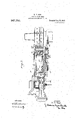
- FIG. 1 is a plan view partly .in section showing my improved swinging coupler 4frame for carrying. a coupler; Fig. .2 is a vertical lon itudinal section; Figs and 4:- Aare vertica cross. sections on, the lines lll-lll andk liv-FV, respectively, of
- My 'device comprises two main elements, namely,'a coupler frame which carries the coupler firmly, and is adaptedto move backand forth longitudinally under the stresses ofbufiin and. draft, and a draft rigging whose yo e is pivotally connected to the car structure moves ra ially as the car passes around qurves.
- a draft rigging whose yo e is pivotally connected to the car structure moves ra ially as the car passes around qurves.
- My invention meets these conditions satisfactorily and a'ords a useful and ein# cient device.
- 2 is the car coupler hfav- .ing a"rearwardly projecting shank 3.
- coupler frame by which the coupler is held and carried consists of four plates or pieces
- the middle portion of the ,frame is box-like, substantially rectangular in cross section, andV has opposite side plates 4l, a top plate 5, and a bottoni plate 6.
- the vside plates d are anged,
- top plate 5 is shaped to fit over the danges of the side plates and has near its mar ins shoulders to engagewith the lips an 'v is permanently secured to the danges by rivets 7.
- the interior of the top plate is recessed
- the bottom plate 6 tits', against the bottom anges of the Side plates'et, and is held thereto preferably by bolts 9, ⁇ so that the bottom plate can be readily detached in order to remove the draft.
- This bottom'plate is also recessed to receive'the lower arm ofthe yoke 8.
- the draft rigging comprises a yoke 8, which is pivoted to a bracket on the car frame at 12, the yoke being reinforced at 13 to give additional wearing surface around the pivot pin.
- the yoke is thus pivotally attached to the bracket 14 and extends forwardly Within the coupler frame or box above described.
- llt contains followers 15, 16, and interposed spring and frictional draft rigging 17, the forward followers 15 engaging stops 18 on the inner surfaces of Athe side plates, and the rear follower 16 also ⁇ 'engaging the curved lug which constitutes the forward end of the bracket la.
- At radial draft gear comprising a coup l ler having a shank and a coupler frame made of four pieces fixed together and xed to the coupler shank, and a draft riggin pivotally connected to the car frame, sai draft rigging fitting Within the coupler frame and the latter moving telescopically thereon, substantially as described.
- a radial draft gear comprising a coupyler having a shank and a coupler frame 3.
- a radial draft gear comprising a coupler havingv a shank anda coupler frame made of four pieces xed together and fixed to the coupler shank, and a draft rigging pivotally connected to the car frame, sai
- a horizontal member of a couplerframe for radial draft gears having near its margins shoulders for engagin side members of such frame, and having olt-holes.
- a bottom member for a coupler-frame for radial draft gears having a downwardly projecting member for affording sliding engagement with a truck-connection.
Landscapes
- Engineering & Computer Science (AREA)
- Mechanical Engineering (AREA)
- Aiming, Guidance, Guns With A Light Source, Armor, Camouflage, And Targets (AREA)
Description
H. F. POPE.
RADIAL DRAFT GEAR.
APPLICATION FILED MAB. 30, 190e.
Patented Ja11.25, 1910.
3 SHEETS-SHEET 1.
Q@ www Mh W I WITNESSES 3 SHEETS-SHEET 2.
H. F. POPE.
RADIAL DRAFT GEAR.
v APPLIUATION FILED MAR. so, 190s. 947,756.
WITN ESS ES f H. F. POPE.
RADIAL DRAFT GEAR.
APPLIUATION FILED MAR. 30, 19.08.
Patented Jan.251910.
3 SHEETS-SHEBT 3.
@www
W fw/ m l\\W/m WITN ESSES accompanying drawings, forming'part of'v nanarnI-rorn, or" onnvnnaiin, omo, 'asistencia ro THE martelaar. MaLLnnnLn ons'rrlves normanna, or ennvnnann, onto, a coona'rion or omo.
oaa'iae.
l Specification oi. Letters lfatent. Application led. March 30, 1908. Serial No. 424,001.
rate tea aan.. ea, raro.
To all whom if 'may concern." c
lBe it known that "l, HENRY F. Porn, of Cleveland, Cuyahoga county,'0hio, lhave invented a new and useful Radial Draft-Gear, of which the following is a full, clear, and exact description, referencey being had to the this specification, in which-- p Figure 1 is a plan view partly .in section showing my improved swinging coupler 4frame for carrying. a coupler; Fig. .2 is a vertical lon itudinal section; Figs and 4:- Aare vertica cross. sections on, the lines lll-lll andk liv-FV, respectively, of
My 'device comprises two main elements, namely,'a coupler frame which carries the coupler firmly, and is adaptedto move backand forth longitudinally under the stresses ofbufiin and. draft, and a draft rigging whose yo e is pivotally connected to the car structure moves ra ially as the car passes around qurves. In devicesof this kind itis of the greatest 'importance that the connection with the'coupler be secureand permanent and that the coupler be properly tted to the draft rigging, for the parts are subject to severe strains of use; and to repair them is costly and entails a loss of use of thecars. My invention meets these conditions satisfactorily and a'ords a useful and ein# cient device.
In the drawings, 2 is the car coupler hfav- .ing a"rearwardly projecting shank 3. The
coupler frame by which the coupler is held and carried, consists of four plates or pieces,
constituting respectively the top,bottom and sides. As shown in Fig. Il, the middle portion of the ,frame is box-like, substantially rectangular in cross section, andV has opposite side plates 4l, a top plate 5, and a bottoni plate 6. The vside plates d are anged,
and are preferably lipped at b, and the top plate 5 is shaped to fit over the danges of the side plates and has near its mar ins shoulders to engagewith the lips an 'v is permanently secured to the danges by rivets 7.
The interior of the top plate is recessed,
E' as shown in Fig.. a, so as to accommodate the ler frame.
l attached to the car frame.
yoke 8 of the draft rigging. The bottom plate 6 tits', against the bottom anges of the Side plates'et, and is held thereto preferably by bolts 9, `so that the bottom plate can be readily detached in order to remove the draft.
rigging. This bottom'plateis also recessed to receive'the lower arm ofthe yoke 8. At
the 'forward part of the frame where it lits around the coupler shank 3, the top `plate deflectsinwardly, as shown at 10 in Fi 2and Vin cross section in Fig. 3, and the si e lates are of less vertical height in order to t the reduced space @tween the top and bottom plates. These plates lit against the shank of the coupler, which is interposed between them, and in addition to the bolts by which the top and bottom plates are secured to the side plates, as shown in Fig. `3, there are also horizontal through-boltsll, which eX- tend through the side plates and through they coupler shank and ix this shaft to the coup- 'lhe top plate also has attached to or made integral with it a lug on which the coupler unlocking lever is pivoted (Fig. 2) and the bottom plate has alsoa similar lug,
shown in Fig. 2, Ito which the unlocking n lever of a bottom-opening coupler can be pivoted.` The draft rigging comprises a yoke 8, which is pivoted to a bracket on the car frame at 12, the yoke being reinforced at 13 to give additional wearing surface around the pivot pin. The yoke is thus pivotally attached to the bracket 14 and extends forwardly Within the coupler frame or box above described. llt contains followers 15, 16, and interposed spring and frictional draft rigging 17, the forward followers 15 engaging stops 18 on the inner surfaces of Athe side plates, and the rear follower 16 also `'engaging the curved lug which constitutes the forward end of the bracket la. lhe box or coupler frame is thus' telescopieally inounted on the draft rigging and slides back and. forth thereon under the stresses of budin and draft, and the whole structure moves iaially on the pivot by which the yoke is ilhe coupler frame or `box is connected with the car truck 19by spring 'guiding connections 20.
Within the scope of'iny invention as defined in the claims, the partsinay be inedilied' since 4 "What ll claim is:
1. At radial draft gear, comprising a coup l ler having a shank and a coupler frame made of four pieces fixed together and xed to the coupler shank, and a draft riggin pivotally connected to the car frame, sai draft rigging fitting Within the coupler frame and the latter moving telescopically thereon, substantially as described.
2. A radial draft gear comprising a coupyler having a shank and a coupler frame 3. A radial draft gear comprising a coupler havingv a shank anda coupler frame made of four pieces xed together and fixed to the coupler shank, and a draft rigging pivotally connected to the car frame, sai
draft rig ing fitting within the coupler frame an the latter movin telescopically thereon, said frame' being re uced at lts forward end where it fits around the coupler shank, and being secured to the coupler shank by through-bolts, substantially as described.
4. A horizontal member of a couplerframe for radial draft gears having near its margins shoulders for engagin side members of such frame, and having olt-holes.
5. A bottom member for a coupler-frame for radial draft gears having a downwardly projecting member for affording sliding engagement with a truck-connection.
In testimony whereof, I have hereunto set my hand.
HENRY F. POPE.
Witnesses;
JOHN Mmmm, H. M. ConwIN.l
Priority Applications (1)
| Application Number | Priority Date | Filing Date | Title |
|---|---|---|---|
| US42400108A US947756A (en) | 1908-03-30 | 1908-03-30 | Radial draft-gear. |
Applications Claiming Priority (1)
| Application Number | Priority Date | Filing Date | Title |
|---|---|---|---|
| US42400108A US947756A (en) | 1908-03-30 | 1908-03-30 | Radial draft-gear. |
Publications (1)
| Publication Number | Publication Date |
|---|---|
| US947756A true US947756A (en) | 1910-01-25 |
Family
ID=3016174
Family Applications (1)
| Application Number | Title | Priority Date | Filing Date |
|---|---|---|---|
| US42400108A Expired - Lifetime US947756A (en) | 1908-03-30 | 1908-03-30 | Radial draft-gear. |
Country Status (1)
| Country | Link |
|---|---|
| US (1) | US947756A (en) |
-
1908
- 1908-03-30 US US42400108A patent/US947756A/en not_active Expired - Lifetime
Similar Documents
| Publication | Publication Date | Title |
|---|---|---|
| US1231619A (en) | Radial-draft gear. | |
| US1076912A (en) | Draft-gear for railway-cars. | |
| US1012451A (en) | Vestibule system for railroad-cars. | |
| US900026A (en) | Radial draft-gear. | |
| USRE12378E (en) | Reissued aug | |
| US1070446A (en) | Draft and buffing mechanism for railway-cars. | |
| US1013073A (en) | Radial-draft gear. | |
| US1884521A (en) | Draft rigging | |
| US984937A (en) | Radial-draft gear. | |
| US449828A (en) | Device for relieving the tension of draw-bars | |
| US478993A (en) | James c | |
| US966656A (en) | Draft-gearing. | |
| US146154A (en) | Improvement in car-couplings | |
| US1023109A (en) | Draft-gear. | |
| US388633A (en) | Car-coupling | |
| US411176A (en) | watson | |
| US773737A (en) | Draw-gear for cars. | |
| US1679301A (en) | Draft gear | |
| US259719A (en) | Car-coupling | |
| US1060698A (en) | Friction draft-rigging for railway-cars. | |
| US775606A (en) | Draft-rigging for railway-cars. | |
| US464381A (en) | Locomotive-coupling | |
| US719989A (en) | Draft-block attachment for freight-cars. | |
| US312156A (en) | Philip j | |
| US987432A (en) | Draft-gear. |