US947246A - Apparatus for detecting and exhibiting the fluorescence of fluorescent substances. - Google Patents
Apparatus for detecting and exhibiting the fluorescence of fluorescent substances. Download PDFInfo
- Publication number
- US947246A US947246A US46097508A US1908460975A US947246A US 947246 A US947246 A US 947246A US 46097508 A US46097508 A US 46097508A US 1908460975 A US1908460975 A US 1908460975A US 947246 A US947246 A US 947246A
- Authority
- US
- United States
- Prior art keywords
- cylinder
- light
- chamber
- fluorescence
- exhibiting
- Prior art date
- Legal status (The legal status is an assumption and is not a legal conclusion. Google has not performed a legal analysis and makes no representation as to the accuracy of the status listed.)
- Expired - Lifetime
Links
- 230000001747 exhibiting effect Effects 0.000 title description 9
- 239000000126 substance Substances 0.000 title description 8
- 239000000463 material Substances 0.000 description 14
- 239000010437 gem Substances 0.000 description 13
- 229910001751 gemstone Inorganic materials 0.000 description 9
- 239000011521 glass Substances 0.000 description 8
- 229910052751 metal Inorganic materials 0.000 description 8
- 239000002184 metal Substances 0.000 description 8
- 239000007789 gas Substances 0.000 description 6
- 239000000123 paper Substances 0.000 description 4
- 239000010453 quartz Substances 0.000 description 4
- VYPSYNLAJGMNEJ-UHFFFAOYSA-N silicon dioxide Inorganic materials O=[Si]=O VYPSYNLAJGMNEJ-UHFFFAOYSA-N 0.000 description 4
- 208000027418 Wounds and injury Diseases 0.000 description 3
- 238000010276 construction Methods 0.000 description 3
- 229910052500 inorganic mineral Inorganic materials 0.000 description 3
- 239000011707 mineral Substances 0.000 description 3
- 239000000843 powder Substances 0.000 description 3
- 239000002023 wood Substances 0.000 description 3
- RTZKZFJDLAIYFH-UHFFFAOYSA-N Diethyl ether Chemical compound CCOCC RTZKZFJDLAIYFH-UHFFFAOYSA-N 0.000 description 2
- XEEYBQQBJWHFJM-UHFFFAOYSA-N Iron Chemical compound [Fe] XEEYBQQBJWHFJM-UHFFFAOYSA-N 0.000 description 2
- 229920002892 amber Polymers 0.000 description 2
- 239000003086 colorant Substances 0.000 description 2
- 230000006378 damage Effects 0.000 description 2
- 230000000694 effects Effects 0.000 description 2
- 208000014674 injury Diseases 0.000 description 2
- 239000007788 liquid Substances 0.000 description 2
- 238000000034 method Methods 0.000 description 2
- 210000003813 thumb Anatomy 0.000 description 2
- 206010010071 Coma Diseases 0.000 description 1
- RYGMFSIKBFXOCR-UHFFFAOYSA-N Copper Chemical compound [Cu] RYGMFSIKBFXOCR-UHFFFAOYSA-N 0.000 description 1
- 241000345822 Cylindera <genus> Species 0.000 description 1
- 229920001875 Ebonite Polymers 0.000 description 1
- 206010056740 Genital discharge Diseases 0.000 description 1
- 101100400378 Mus musculus Marveld2 gene Proteins 0.000 description 1
- 238000010521 absorption reaction Methods 0.000 description 1
- 238000007792 addition Methods 0.000 description 1
- 229910052782 aluminium Inorganic materials 0.000 description 1
- XAGFODPZIPBFFR-UHFFFAOYSA-N aluminium Chemical compound [Al] XAGFODPZIPBFFR-UHFFFAOYSA-N 0.000 description 1
- BIGPRXCJEDHCLP-UHFFFAOYSA-N ammonium bisulfate Chemical compound [NH4+].OS([O-])(=O)=O BIGPRXCJEDHCLP-UHFFFAOYSA-N 0.000 description 1
- 210000000078 claw Anatomy 0.000 description 1
- 230000000052 comparative effect Effects 0.000 description 1
- 229910052802 copper Inorganic materials 0.000 description 1
- 239000010949 copper Substances 0.000 description 1
- 239000007799 cork Substances 0.000 description 1
- 238000010892 electric spark Methods 0.000 description 1
- 239000004744 fabric Substances 0.000 description 1
- 239000000835 fiber Substances 0.000 description 1
- 239000005357 flat glass Substances 0.000 description 1
- 239000007850 fluorescent dye Substances 0.000 description 1
- 239000003292 glue Substances 0.000 description 1
- 238000003780 insertion Methods 0.000 description 1
- 230000037431 insertion Effects 0.000 description 1
- 238000007689 inspection Methods 0.000 description 1
- 238000009434 installation Methods 0.000 description 1
- 239000011810 insulating material Substances 0.000 description 1
- 229910052742 iron Inorganic materials 0.000 description 1
- 239000002480 mineral oil Substances 0.000 description 1
- 239000000203 mixture Substances 0.000 description 1
- 239000005304 optical glass Substances 0.000 description 1
- 238000005192 partition Methods 0.000 description 1
- 230000002688 persistence Effects 0.000 description 1
- 239000007787 solid Substances 0.000 description 1
- 238000001228 spectrum Methods 0.000 description 1
- 238000006467 substitution reaction Methods 0.000 description 1
- 239000012780 transparent material Substances 0.000 description 1
- 239000002966 varnish Substances 0.000 description 1
- 210000000707 wrist Anatomy 0.000 description 1
Images


Classifications
-
- G—PHYSICS
- G01—MEASURING; TESTING
- G01N—INVESTIGATING OR ANALYSING MATERIALS BY DETERMINING THEIR CHEMICAL OR PHYSICAL PROPERTIES
- G01N21/00—Investigating or analysing materials by the use of optical means, i.e. using sub-millimetre waves, infrared, visible or ultraviolet light
- G01N21/62—Systems in which the material investigated is excited whereby it emits light or causes a change in wavelength of the incident light
- G01N21/63—Systems in which the material investigated is excited whereby it emits light or causes a change in wavelength of the incident light optically excited
- G01N21/64—Fluorescence; Phosphorescence
Definitions
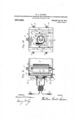
- Figure 1 is a horizontal section about half size of one disposition of.
- Fig.2vis a vertical section on a smaller scale of another disposition of the parts of the apparat'usy Fig. 3. is a sectional view taken on the line 3, Fig. 2, looking in the. direction of "the arrow or as seen from the eye-shield,
- FIG. 4 is a sectional view taken on the line 4 Fig. 2 looking in the direction of the arrow.
- Fig. 5 is a sectional viewtaken'on the line 5 Fig. looking in the di rection of the arrow.
- F g.6 is aside ele-fvation of .anattachment for producing a- I spark gap light as it appearsin place at G, Fig. 1.
- Fig, 7 is a,horizontal section of Fig. fi'through'the line 7 Fig. 6.
- Fig. 8 is a triplex 'Inodification of the eye sh eld C, F g. 1.
- Fig. 9, is a vertical'longitudinal section of part of the chamber 0 Fig. 2
- Fig. 10 1s a sectlonal vlew taken on Pa-tented Jan. 25, "1910.
- FIG. 1, 2 and Si a casesimilar 'in-construction to that of an ordinary X ray fiuoro'scope without the X ray screen which is provided with the usual handle B, Figs. 1,"a-nd 2 and chenille edged shield for the .eyes C, Figs. 1, 2 and8.
- Within the eye shield is a screenN, Figs. 1, and 2, of a yellow or other colored transparent material as vglass which is held in place by a groove 0, c, a frame 0 and a p1n d, Fig.-
- Fig. 1 is a separate chamber which fits telescopically over the posterior end of the eye shleld case C, and is provided with a close fitting cover E; Figs. 1 and 6.
- projections extend over and undert-he chamber D, in Fig. 1, and are sljgt ted to correspond to thumb screws, shti'wn at an a a, Fig. 6, which are fixed to the top 'j-andbottom of D, in the wooden corner stri s, whereby the chamber D is strengthene ⁇ ;-The chamber H may thereby be clamptl to.- D, [or removed at pleasure,
- the chamber H is provided with a door not shown in the section, similar to that shown at K,Figs. l and 2, but directly over G, Fig. 1, so that rayfilters such. as G mayfbe inserted or withdrawn without detaching the chamber H.
- The'chamber H is provided at its posterior end with a plano of H previously described.
- convex or other lens I, Figs. 1 and 2 is of such a length that the cone of condensed light formed when the direct rays of the sun, or a beam of parallel rays" from a lantern are transmitted through the lens I, Fig. 1, and .the ray filter aperture G, Fig. 1,
- This lens I, Figs. 1 and 2 should be such as generally used for the front lens of the familiar triple lantern condenser, about 5?; inches in diameter, and have a focal length bf about 9 inches, although smaller or largerlenses may be used.
- ray filter which may be a sheet of glass as shown, or a cell or a flat bottle containing a liquid, mounted on a siiitable frame, of such a size that it may be'inserted in a grooved light locked recess f f, through the door K, Figs. 1 and 2.
- a ray filter G or a ray filter J, or both combined is formed about midway within the dark chamber D.
- the opposite opening on the left hand side of the dark chamber D, shown in the horizontal'sectional Fig. 1, at L is to be large enough to admit the hand. It maybe closed by a door or it may have attached to it asleeve made of flexible material such as suede kid, a part of which is shown at M, Fig. 1. Through this sleeve the hand and wrist may be inserted and thus a gem, a mineral specimen or any other object may be held in the hand within the dark chamber D, and turned. about at pleasure for examination on all sides in the focus of intense light produced by the lens'I and admitted through the ray. filter G or J or both combined. In case it is preferred to use the cover E Figs.
- the specimens may be supported in ordinary pin clamps or on a block of wood in the chamber D.
- the section H is provided with a handle, shown at B; Fig. 2.
- Fig. 2 is a dark chamber which may be substituted for D,' Fig. 1, intermediate between A and H, all three sections being A fits telescopically in O and H is attached to O as shown in Fig. 2 by thumb screws u a a u Fig. 10-cor'responding to the slots in the projecting ends ,end by a blackened'thin metal plate g, Figs;
- tion 72 in its center, which may be any de sired size or shape. In the drawings this end of its shaft to rest upon,
- perforation h is represented as a circular a opening about i of an inch in diameter.
- tlllS perforated metal plate To tlllS perforated metal plate a circular disk is attached, which is revolublc upon a central plvot 2', Flgs. 2 and 4. This disk is perforated by a serles of apertures k. k.
- a recess formed by a wooden frame F F F" and springs if b F igs..9 and 10 may be provided similar in size to that shown in Figs. 1 (3 and 7 and in which the ray filters such as G Fig. 1 or other accessories such as T Fig. (3 which fit in the recess F F F Figs. 1 6 and 7 may be lnserted to cover the opening 71 Figs. 2,, 3, 9 and 10.
- Such of these accessories as are to be used while the chamber H is attached to 0 may be inserted and withdrawn through a door K Fig. 2.
- the apparatus When the apparatus, as arranged in Fig. 2, is ointed toward the sun or when a suitable Eeam of light is otherwise directed into 'it normally through the lens I, the condensed rays pass through the small opening in the posterior end of O, and come to a focus about 1?; inches therefrom, within the chamber 0.
- a small electro-motor S provided with a shaft which extends on one side about 1 inch beyond its bearing, vertically into the chamber 0, centrally between its sides, and
- a light cylindrical r Upon the shaft ofhe electro-motor within the chamber 0 is fitted a light cylindrical r a bottom' of wood a out *3 of an inch thick is Cir satisfactory. In the center of the bottom of this box is fixed a metal tapered socket 0, Figs. 2 and 3, in which the shaft of the electro-motor fits by friction, so that it will be revolved by the motor but may be removed 1 I and replaced promptly, as may be desired,,.
- This cover need not be hinged but is held in place by turn buckles only.
- the cylinder P is perforatedv with one similar aperture 1", Fig. 3, and the situation of the cylinder within the chamber 0 is such that the beam of light from the lens I comes to a focus about in the axis of the cylinder, when these openings coincide.
- the cylinder P, Figs. 2 and 3 is provided J with a cover furnished with a central, (peri of the-cylinder, in which similar-5 be'inse'rted.
- a cover furnished with a central, (peri of the-cylinder, in which similar-5 be'inse'rted.
- a claw clam or ho ding a gem is shown at s, Fig. 3, ad usted asall should be to hold the object under inspection about 0 posite the opening in the cylinder. If the ob ect thus supported within the cylinder is especially irre ular in form, the clamp selected to hol it should permit of its adjustment so that its weight will be distributed around the axis as uniformly as possible.
- the door to, Fig. 2 is provided with a metal fitting as, similar to that.” the cover held in a fixed position the cen box with "a cylinder and does not turn with it. This method of examination is more partlcularly pplicable to transparent gems.
- the material to be examined instead of being a single piece which may be held in the center of the cylinderas above desbribed, a powder, it may be dusted upon a strip 'of paper reviously coated with glue or varnish, am when dry wrapped around ⁇ the outsideof the cylinder. 4
- the strip of paper should be as wide as the height ofthe cylinder and a little longer than its circumfer ence, and held about the cylinderbya couple of rubber bands.
- the sanded surface should be the full length of the paper (or circumference of the cylinder) but need not be wider than the aperture h, F igs; 2, 3, and 4. Thus but a small quantity of material is sufficient.
- a solid cylinder of the material may be used if desired.
- the accessory 1 Figs. 4 and 6 and 1 Figs. 9 and 10 is a so called spark gap lamp and is provided to permit the substitution of the light from high tension electric sparks for light from other sources, with either arrangement of the fiuoroscope, Figs. 1 and 2.
- the spark gap lamp consists of aplate of insulating material, perforated With a rectilinear opening within which three or more iron balls are supported, nearly in contact. Although only three balls are shown, four ormore may be used to provide for a greater number of s arks, when desired.
- Fig. 4 it is '100 fastene either in place of, or superposed over a ray filter of 'the same size and shape, and is to be brought opposite the opening it, for use with the revoluble cylinder.
- the same appliance is. held in place by the.screws n, n, n, it, over a central perforation-in a' by clamps to the revoluble disk,
- Fig. 1 a similar lainp 1 is shown attached to a likesupport T ,,in a-re cess F F F similar to that above described but upon, the end of the chamber 0 Fig. 2, to be used with the revoluble cylinder.
- The. support T with this form of the spark gap lamp and its accessories may also be inserte in the recess F F F Figs. 1, 6 and7 to be used with'the chamber D as above described.
- the wires 2 2, Figs. 4, 6 and 10 are to be connected with a suiiiciently capable induc/ -tion coil and high tension 'elee'tric sparks enough to inclose it.
- Fig. 1 or Fig. 2 To use the apparatus arranged either as in Fig. 1 or Fig. 2 it may be held in the hand or mounted upon an equatorial telescope stand which need 'be only of the simplest construction as it may be well enough adjusted by hand, and thus directed toward the sun. Both these methods are more convenient in the winter when the sun is-low than in the summer when the sun is hlgh,
- the appa tus thus described is applicable rranged as in Fig. 1, it serves he direet fluorescenceof gems and other objects held in the focus of intense light from the lens.
- the ray filter most used for the incident light should transmit only blue, violet and ultraviolet rays.
- the best two materials at present available for this purpose area solution of ammonia sulfate. of copper and ablue violet glass.
- the eye screen most used should have a colorwhich appears yellow to the eye but. which freely the cylinder.
- Ordinary yellow glass will answer fairly well, but a screen such as is used for a photographic color screen or for three color photography is superior.
- .VVhen arranged as in Fig. 2 the apparatus. is applicable for showing'the residual fluorescence or after glow of gems, minerals, fluorescent glass,
- the material be a powder sanded upon a-strip of paper, wound around the cylinder, fresh portions of the powder are constantly illuminated on the side opposite the observer, and if the powderafi'ords a residual fluorescence it is thus excited and appears as a band of colored light, girdling In all (cases the observer sees these effects without apparent interruption,
- gems may be distinguished from imitationsand from each man ⁇ ? minerals identified and distinguished from one another, optical glass selected, ad i'lterations by mineral oils detected tioils, fluorescent dyes detected in .commercial products, and vice versa theielative absorption capacities of ray. filters determined and the fluorogenic efficiency of light from various sources investigated.
- the chambers D and"'-D ⁇ shown in the drawings and herein described as separate may be one and the same-as all the parts of D maybe attached to O and to then use 0 in place ofgD it is only necessary to remove the cylinder P by means of its taper socket and to cover the aperture h.
- any subtance the combination of means for attacha I g a specimen of the material to a revoluble carrier in an inclosing case provided with an aperture or window .for its examination,- means for producing and applying a suit- 40, able light to the specimen, and aJmotor to rotate the carrier and thus ex use the specimenaltern'atel first to'the lig t and/then in obscurity to t e view of the observer, sub stantially as described; 1' 4.
- cence of substances consisting of a case to .inclose a specimen of the material to be ex amined provided with an opening for it's introduction; an aperture or window for its examination; means for roducing and applying the spark gap llght' developed in various gases, and for applying condensed men, either simply held in the rays orattached to or supported within a rotating to the cylinder; ray filters to modify the incident rays and arrest unused rays reflected the observer; means forproducing and applying suitable ray ergy or condensing and applying suitable y ener from other fy the incident rays and arrest unused rays reflected from the s ecimen.
Landscapes
- Health & Medical Sciences (AREA)
- Nuclear Medicine, Radiotherapy & Molecular Imaging (AREA)
- Physics & Mathematics (AREA)
- Life Sciences & Earth Sciences (AREA)
- Chemical & Material Sciences (AREA)
- Analytical Chemistry (AREA)
- Biochemistry (AREA)
- General Health & Medical Sciences (AREA)
- General Physics & Mathematics (AREA)
- Immunology (AREA)
- Pathology (AREA)
- Investigating, Analyzing Materials By Fluorescence Or Luminescence (AREA)
Description
W. G. LEV ISON. Y APPARATUS FOR DETECTING AND EXHIBITING THE FLUORESCENCE 0P FLUORESCENT SUBSTANCES.
- APPLIO-ATIQH TILED nov. 3, 190a.
, 947,246. I PatSnted Jam25,191:0.
3 SHEETS-SHEE'I l.
WITNESSES I v N C INVENTOR %M%2/m@ SS r w. G. Lawson.- v APPARATUS FOR DETECTING ANP EXHIBITING THE FLUORESCENCE 0F, FLUORESGEKT SUBSTANCE S.
urmoulonfrnnn N013! 190s.
Patented Jan 25, 1910.
T W m E N. on CL V m m E WITNESSES:
. w. G. nvxsoN. v APPARATUS FOBDETBGTING AND EXHIBITING TKBPLUORESGENGE 0F FLUORESGBN T SUBSTANCES. A APYLIOATION FILED NOV. 3, 1908. 947,246. v 1 Patented Jan. 25, 1910.
3 SHEETS-BHEB'I 3.
WIT/ 5.985s.- INVENTOI? WALLACE GOOLID LEVISON, F BROOKLYN, NEW YORK.
nrrnnatros FOB nn'rno'rriw Am Specification of Letters Patent. Application filed li'ovember 3, 1968. Serial No. 460,975.
EXHIBITING THE FLUORESCENCE OF FLUORESCENT SUBSTANCES.
To all whom it concern:
Be it known that I, WALLACE GooLD -LEVI son, a citizen .of the borough ofBrooklyn,
count of Kings, andState of New. York,
have invented a new-and useful rovement in apparatus in the class of nowscopes for detecting and exhibiting the fluorescence of fluorescent, substances for yarious practlcal purposes and the following is a description of my lnventlon, such as "will enable others skilled in the arts to which it belongs to make and use it, refer ence being made to the accompanying draw.-
I venience of explanationis included in the It consists of a case or box which 1s,port- "able if constructed of suitable light materials as cardboard or aluminum and of several sections fitting to ether'asherem described-for the practic'a use of jewelers, an-
alyticalchemists and others, or. it may be constructed of heavier material for 1 errnanent installation as a museum exhibit It consists in partof additions to the apparatus describedin my previous patent No. 883,653 March 31, 1908, which for conpresent description but 'onlythe additional parts which greatly increase its utility are the object of this application.
In the drawings Figure 1 is a horizontal section about half size of one disposition of.
the pa'rts of the apparatus. Fig.2vis a vertical section on a smaller scale of another disposition of the parts of the apparat'usy Fig. 3. is a sectional view taken on the line 3, Fig. 2, looking in the. direction of "the arrow or as seen from the eye-shield,
with the cylinder partly cut away to show an aperture in it for the admission. of.
light; Fig. 4 is a sectional view taken on the line 4 Fig. 2 looking in the direction of the arrow. Fig. 5 is a sectional viewtaken'on the line 5 Fig. looking in the di rection of the arrow. F g.6 is aside ele-fvation of .anattachment for producing a- I spark gap light as it appearsin place at G, Fig. 1.
Fig, 7 is a,horizontal section of Fig. fi'through'the line 7 Fig. 6. Fig. 8 is a triplex 'Inodification of the eye sh eld C, F g. 1. Fig. 9, is a vertical'longitudinal section of part of the chamber 0 Fig. 2
provided with a rabbeted recess similar to that shown in Figs. 1, 6, and 7, instead of the revoluble disk shown in Fig. 4, and with a spark gap lamp'in'closed in aieontainer for using various gases, in place in the recess. Fig. 10. 1s a sectlonal vlew taken on Pa-tented Jan. 25, "1910.
the line 10. Fig. -9 lookingjin the direction a of the arrows.
' In the drawings like letter's indicate like arts.
A. Figs. 1, 2 and Sis a casesimilar 'in-construction to that of an ordinary X ray fiuoro'scope without the X ray screen which is provided with the usual handle B, Figs. 1,"a-nd 2 and chenille edged shield for the .eyes C, Figs. 1, 2 and8. Within the eye shield is a screenN, Figs. 1, and 2, of a yellow or other colored transparent material as vglass which is held in place by a groove 0, c, a frame 0 and a p1n d, Fig.-
2 and is removable by lifting the pin d by the spring e to which it is attached.
D Fig. 1 is a separate chamber which fits telescopically over the posterior end of the eye shleld case C, and is provided with a close fitting cover E; Figs. 1 and 6. This chamber D,-
1, is also provided with opposite openings in its two sides. The one on the right hand side of a person looking in the eye shield C is surrounded with a frame F, F F, Figs. 1, 6 and 7 which forms a rabbete'd recess to permit the insertion of ray filters which maybe suitable liquids in closed in flat glass bottles, or cells, or plates of suitably colored glass as G Fig. 1, and
also of the board T, Fig. 6, perforated at t, and supporting the appliance 1*, Figs; 6, 7
and 4,1or the board T supporting the spark gas lamp 1 Figs. 9 and 10. Either of these is held in place by the springs b 12, Figs. 1,
6 and 7. To this side of the chamber D there is fitted at right angles'the extension H, Figs. 1 and 2,"the top and bottom of which project two inches beyond its sides.
These projections extend over and undert-he chamber D, in Fig. 1, and are sljgt ted to correspond to thumb screws, shti'wn at an a a, Fig. 6, which are fixed to the top 'j-andbottom of D, in the wooden corner stri s, whereby the chamber D is strengthene {;-The chamber H may thereby be clamptl to.- D, [or removed at pleasure, The chamber H is provided with a door not shown in the section, similar to that shown at K,Figs. l and 2, but directly over G, Fig. 1, so that rayfilters such. as G mayfbe inserted or withdrawn without detaching the chamber H. The'chamber H is provided at its posterior end with a plano of H previously described.
convex or other lens I, Figs. 1 and 2, and is of such a length that the cone of condensed light formed when the direct rays of the sun, or a beam of parallel rays" from a lantern are transmitted through the lens I, Fig. 1, and .the ray filter aperture G, Fig. 1,
, comes to a focus about 1% inches within the section'D, Fig. 1. This lens I, Figs. 1 and 2, should be such as generally used for the front lens of the familiar triple lantern condenser, about 5?; inches in diameter, and have a focal length bf about 9 inches, although smaller or largerlenses may be used.
J, Figs. 1 and 2 is another ray filter, which may be a sheet of glass as shown, or a cell or a flat bottle containing a liquid, mounted on a siiitable frame, of such a size that it may be'inserted in a grooved light locked recess f f, through the door K, Figs. 1 and 2. Thus an intense focus of light from the lens I, colored as desired, either by a ray filter G or a ray filter J, or both combined, is formed about midway within the dark chamber D.
The opposite opening on the left hand side of the dark chamber D, shown in the horizontal'sectional Fig. 1, at L is to be large enough to admit the hand. It maybe closed by a door or it may have attached to it asleeve made of flexible material such as suede kid, a part of which is shown at M, Fig. 1. Through this sleeve the hand and wrist may be inserted and thus a gem, a mineral specimen or any other object may be held in the hand within the dark chamber D, and turned. about at pleasure for examination on all sides in the focus of intense light produced by the lens'I and admitted through the ray. filter G or J or both combined. In case it is preferred to use the cover E Figs. 1 and 6, or an ordinary door as previously mentioned for the opening L, in place of the sleeve M Fig. 1, to introduce specimens for a lengthy examination, instead of holding them in the hand through the sleeve M, the specimens may be supported in ordinary pin clamps or on a block of wood in the chamber D.
disposed in line.
In order to facilitate the handling of the apparatus when these parts are thus coma bined, the section H is provided with a handle, shown at B; Fig. 2.
0, Fig. 2 is a dark chamber which may be substituted for D,' Fig. 1, intermediate between A and H, all three sections being A fits telescopically in O and H is attached to O as shown in Fig. 2 by thumb screws u a a u Fig. 10-cor'responding to the slots in the projecting ends ,end by a blackened'thin metal plate g, Figs;
'2, 3, 4, 5, 9 and 10, having a perfo'ra;
"tion 72. in its center, which may be any de sired size or shape. In the drawings this end of its shaft to rest upon,
perforation h is represented as a circular a opening about i of an inch in diameter. To tlllS perforated metal plate a circular disk is attached, which is revolublc upon a central plvot 2', Flgs. 2 and 4. This disk is perforated by a serles of apertures k. k.
.10 In. F. k. Fig. 4 which may be successively brought to coincide with h andmay be larger or smaller than It or differ from it in shape as desired. In the drawing they are represented as circular and a little larger in diameter than it. One of these apertures indicated by In, Fig. 4, is left uncovered. The others are covered by pieces of glass of various colors, or provided with other accessories. These objects may be V shaped as shown at Z Z Z Z Z and affixed by clamps m m m &c., arranged as shown in Fig. at, or as the screws 11. n n n are disposed in Fig. 6. In the latter case the objects are easily removable or interchangeable.
Instead of the revoluble disk shown in Fig. 4: upon the metal plate' forming theend of the chamber'O a recess formed by a wooden frame F F F" and springs if b F igs..9 and 10 may be provided similar in size to that shown in Figs. 1 (3 and 7 and in which the ray filters such as G Fig. 1 or other accessories such as T Fig. (3 which fit in the recess F F F Figs. 1 6 and 7 may be lnserted to cover the opening 71 Figs. 2,, 3, 9 and 10. Such of these accessories as are to be used while the chamber H is attached to 0 may be inserted and withdrawn through a door K Fig. 2.
When the apparatus, as arranged in Fig. 2, is ointed toward the sun or when a suitable Eeam of light is otherwise directed into 'it normally through the lens I, the condensed rays pass through the small opening in the posterior end of O, and come to a focus about 1?; inches therefrom, within the chamber 0.
Upon the underside of the section 0 is attached a small electro-motor S provided with a shaft which extends on one side about 1 inch beyond its bearing, vertically into the chamber 0, centrally between its sides, and
at about lg inches from the aperture in itsposterior end. An electro-magnet is better adapted for this purpose if provided with a jewel or other hard bearingfor the lower thus enabling it to run with less friction when the shaft is vertical. In the portable form of instru-' ment shown in ,Fig. 2 the motor is to be operated by a current 'led by convenient flexible wires from a suitable small battery through a switch or key 1;, Fig. 2, conveniently situated, by which it may be started or stopped at pleasure In place of the electromotor a high geared hand motor may be used but less effectively.
Upon the shaft ofhe electro-motor within the chamber 0 is fitted a light cylindrical r a bottom' of wood a out *3 of an inch thick is Cir satisfactory. In the center of the bottom of this box is fixed a metal tapered socket 0, Figs. 2 and 3, in which the shaft of the electro-motor fits by friction, so that it will be revolved by the motor but may be removed 1 I and replaced promptly, as may be desired,,.
through an aperture 1n the chamber 0 directly over it, which is 3 by 4 inches in size, lar e enou h to admit the hand, and provide with a ight locked cover w, Fig. 2.
This cover need not be hinged but is held in place by turn buckles only.
Opposite the aperture h, Fig. 2, in the posterior end of the chamber 0, the cylinder P is perforatedv with one similar aperture 1", Fig. 3, and the situation of the cylinder within the chamber 0 is such that the beam of light from the lens I comes to a focus about in the axis of the cylinder, when these openings coincide.
cylinder should any direct light be visible,
In no osition of the through the eye shield, when the instrument is directed toward a source of light. Partitions Y Y, Fig. 5 projecting from the sides of the chamber 0, and almost touching the cylinder, may be added to interce t the view of any light reflected from the cy der upon the interior side of the metal plate g, Figs. 2,3, 4 and 5, thus making the obscurity more complete. It is to provide against injury from the heat of the-focus of the beam of light, that the posterior end of the chamber 0 and the cylinder are better made of metal, but if the light is excluded except while the cylinder is revolving, the latter suffers no injury even if made of cardboard.
The cylinder P, Figs. 2 and 3 is provided J with a cover furnished with a central, (peri of the-cylinder, in which similar-5 be'inse'rted. When this is in us of the cylinder is removed and forated metal fitting p, Figs. 2 an through which the wlre shank of a suitable clamp maybe inserted, adjusted as required and fixed in position by the screw 9.
Several kinds of clam s or incers are desirable. A claw clam or ho ding a gem is shown at s, Fig. 3, ad usted asall should be to hold the object under inspection about 0 posite the opening in the cylinder. If the ob ect thus supported within the cylinder is especially irre ular in form, the clamp selected to hol it should permit of its adjustment so that its weight will be distributed around the axis as uniformly as possible.
to avoid difiiculties from the centrifugal force accompanying its rapid revolution with the cylinder.
The door to, Fig. 2, is provided with a metal fitting as, similar to that." the cover held in a fixed position the cen box with "a cylinder and does not turn with it. This method of examination is more partlcularly pplicable to transparent gems.
If the material to be examined, instead of being a single piece which may be held in the center of the cylinderas above desbribed, a powder, it may be dusted upon a strip 'of paper reviously coated with glue or varnish, am when dry wrapped around\ the outsideof the cylinder. 4 The strip of paper should be as wide as the height ofthe cylinder and a little longer than its circumfer ence, and held about the cylinderbya couple of rubber bands. The sanded surface should be the full length of the paper (or circumference of the cylinder) but need not be wider than the aperture h, F igs; 2, 3, and 4. Thus but a small quantity of material is sufficient. A solid cylinder of the material may be used if desired.
The accessory 1 Figs. 4 and 6 and 1 Figs. 9 and 10;is a so called spark gap lamp and is provided to permit the substitution of the light from high tension electric sparks for light from other sources, with either arrangement of the fiuoroscope, Figs. 1 and 2.
-lVhenthis spark gap lamp is in use the lens chamber H may be laid aside The spark gap lamp consists of aplate of insulating material, perforated With a rectilinear opening within which three or more iron balls are supported, nearly in contact. Although only three balls are shown, four ormore may be used to provide for a greater number of s arks, when desired. In Fig. 4, it is '100 fastene either in place of, or superposed over a ray filter of 'the same size and shape, and is to be brought opposite the opening it, for use with the revoluble cylinder. In Fig. 6, the same appliance is. held in place by the.screws n, n, n, it, over a central perforation-in a' by clamps to the revoluble disk,
sheet of thin wood, vulcanized fiber or hard rubber T, which fits into-'the rabbeted. re-
cess 'upon the side of the chamber D, in
place of or superposed over the ray filter G, Fig. 1, as may be desired and to be used with specimens held in the chamber D Fig. 1. In Figs. 9 and 10 a similar lainp 1 is shown attached to a likesupport T ,,in a-re cess F F F similar to that above described but upon, the end of the chamber 0 Fig. 2, to be used with the revoluble cylinder. The. support T with this form of the spark gap lamp and its accessories may also be inserte in the recess F F F Figs. 1, 6 and7 to be used with'the chamber D as above described.
The wires 2 2, Figs. 4, 6 and 10, are to be connected with a suiiiciently capable induc/ -tion coil and high tension 'elee'tric sparks enough to inclose it.
"bottom cut off, fitted I covered with a black cloth or a'dark box in place of the chamber H, to exclude all other light than that of the spark. To serve this and also important additional purposes small cases made of ebon'ite, colore'd glass or other suitable material may be provided attachable easily to the insulating support of the spark gap lampand only just large If the opening over which the spark gap lamp is adjusted is covered with a quartz plate and one of the little cases is provided with inlet and outlet tubes being otherwise fairly air tight it may be kept filled with, and the sparks developed in gases other than. air, and the composition of the light and the effects produced by it thereby varied at pleasure. A case of simple construction for this purpose is shown in Figs. 9 and 10 in which "W is an ordinary wide mouthed bottle of amber glass with the upona soft rubber bandrl surrounding a shoulder of the -sup-. port of the spark gap lamp 1. It is closed with a soft rubber cork Z through which the inlet tube X and the outlettube Y are inserted. Under the electrodes is a window of quartz 6 To fill the case with any desired gas it is only necessary to connect the inlet tube (usually by means of. a rubber tube) with a suitable apparatus for generatingit. 7, f f, is a smaller recess in which the insulating supportof the spark gap lamp I and any ray filter desired may be inserted separately or together and from which the lamp may be lifted with facility to remove the quartz plate 6 whennecessa'ry.
To use the apparatus arranged either as in Fig. 1 or Fig. 2 it may be held in the hand or mounted upon an equatorial telescope stand which need 'be only of the simplest construction as it may be well enough adjusted by hand, and thus directed toward the sun. Both these methods are more convenient in the winter when the sun is-low than in the summer when the sun is hlgh,
and at all seasons it may more conveniently "be placed horizontally upon a table at a-suitable height for a seated observer to .look in the eye shield, and a beam-of sunli a. heliostat or simply a reflecting mirrozepr of light-froman into it. tion with the'spark gap light.
' The appa tus thus described is applicable rranged as in Fig. 1, it serves he direet fluorescenceof gems and other objects held in the focus of intense light from the lens. The ray filter most used for the incident light should transmit only blue, violet and ultraviolet rays. The best two materials at present available for this purpose area solution of ammonia sulfate. of copper and ablue violet glass. The eye screen most used should have a colorwhich appears yellow to the eye but. which freely the cylinder.
- other,
L in the fixe *food and transmits red, orange, yellow, yellow-green and green, arresting the blue and violet colors of the spectrum. Ordinary yellow glass will answer fairly well, but a screen such as is used for a photographic color screen or for three color photography is superior.
.VVhen arranged as in Fig. 2 the apparatus. is applicable for showing'the residual fluorescence or after glow of gems, minerals, fluorescent glass,
ambers, and other substances as follows :When a fluorescent object as an opaque gem isheld by a clamp in the center of the cylinder, and the latter is in rapid revolution, each time the aperture in the cylinder faces the lens the light enters the cylinder and excites the fluorescence of the gem. When the aperture/faces the eye shield, if the gem affords a residual fluorescence or after glow, the observer sees it glowing with the characteristic colored light thereof. When the: gem is held in aclamp attachedto the cylinder and revolves with it, the observer sees the side that had previously been illuminated. If it be a transparent gem held in a fixed position by a clamp. attached to the cover, of the fiuoroscope, the observer sees its previously illuminated side through the gem. If the material be a powder sanded upon a-strip of paper, wound around the cylinder, fresh portions of the powder are constantly illuminated on the side opposite the observer, and if the powderafi'ords a residual fluorescence it is thus excited and appears as a band of colored light, girdling In all (cases the observer sees these effects without apparent interruption,
owing to the persistence of vision.
. By'the aid ofthis apparatus, arranged one way or the other, several gems may be distinguished from imitationsand from each man}? minerals identified and distinguished from one another, optical glass selected, ad i'lterations by mineral oils detected tioils, fluorescent dyes detected in .commercial products, and vice versa theielative absorption capacities of ray. filters determined and the fluorogenic efficiency of light from various sources investigated. i
The chambers D and"'-D {shown in the drawings and herein described as separate may be one and the same-as all the parts of D maybe attached to O and to then use 0 in place ofgD it is only necessary to remove the cylinder P by means of its taper socket and to cover the aperture h.
I herein use'the term residual fluorescencel to designate the same phenomenon that is also commonly calledfphosphores- .cence' or an afterglow.
Having now described the apparatusand its application what I claim-and desire to patent is: t
'1. An apparatus fordisclosing and exhibiting'the residual fluorescence; afterglow, w or so-calledphosphorescence of any sensitive substance consisting of a revoluble perf0-' rated cylinder inclosed in a case provided with an aperture or window for its inspec-' tion; means for attaching a specimen of the material to be examined Within, or upon the outside ofthe'cylinder; means for producing and applying a suitable light to the'specimen; and means for-rotating the cylinder to expose the specimen alternately first to-the light and then'in obscurity to the view of the observer substantially as described.
2.- In an apparatus for detectin and ex hibiting the residual fluorescence 0 any fluo for attaching a specimen of the material to,
a 2 5 or supporting it within a perforated reyoluole cylinder inclosed in a case provided with an eye shield, inbans for producing and applying a suitable light to the specimen,
andme'ans for rotating the cylinder to '-sub-= mit the specimen alternately first to the light and then in obscurity to the view of the observer,- substantially as described. 3. In an apparatus for detectin and exhibiting the residual fluorescence 0 any subtance the combination of means for attacha I g a specimen of the material to a revoluble carrier in an inclosing case provided with an aperture or window .for its examination,- means for producing and applying a suit- 40, able light to the specimen, and aJmotor to rotate the carrier and thus ex use the specimenaltern'atel first to'the lig t and/then in obscurity to t e view of the observer, sub stantially as described; 1' 4. An apparatus for disclosing and exhibiting the comparative efliciency of the spark gap light developed in various gases for excitmg the fluorescence and so-called phosphorescence ofgsubstances c'onsisting'of a case to inclose the material to be excited ro- -sources and ray filters to m yided with 'an'opening for its introduction;
an eye'shieldfor its observation; a'revo'lu porting 1t independently thereof; a motor to- .rotate the carrier; and a spark gap lamp over a window of quartz or other suitable ing the ases; and means for de- 5. An apparatus for 'disclosing and exhibiting both the'direct and residual fluores-.
cence of substances, consisting of a case to .inclose a specimen of the material to be ex amined provided with an opening for it's introduction; an aperture or window for its examination; means for roducing and applying the spark gap llght' developed in various gases, and for applying condensed men, either simply held in the rays orattached to or supported within a rotating to the cylinder; ray filters to modify the incident rays and arrest unused rays reflected the observer; means forproducing and applying suitable ray ergy or condensing and applying suitable y ener from other fy the incident rays and arrest unused rays reflected from the s ecimen.
' I W LAGE-GOOLD LEVISON.
1 Witnesses:
FRANKLIN W. Hoornn,
T CHARLES L. HARRINGTON.
; substantially as dematerial forming part of a small auxiliary case inclosin'g the spark ap lamp rovided' ray energy from other sources, to the speci- I rescen't substance the combination of means cylinder; means forattaching the specimen 'from the specimen; and means for rotating
Priority Applications (1)
| Application Number | Priority Date | Filing Date | Title |
|---|---|---|---|
| US46097508A US947246A (en) | 1908-11-03 | 1908-11-03 | Apparatus for detecting and exhibiting the fluorescence of fluorescent substances. |
Applications Claiming Priority (1)
| Application Number | Priority Date | Filing Date | Title |
|---|---|---|---|
| US46097508A US947246A (en) | 1908-11-03 | 1908-11-03 | Apparatus for detecting and exhibiting the fluorescence of fluorescent substances. |
Publications (1)
| Publication Number | Publication Date |
|---|---|
| US947246A true US947246A (en) | 1910-01-25 |
Family
ID=3015665
Family Applications (1)
| Application Number | Title | Priority Date | Filing Date |
|---|---|---|---|
| US46097508A Expired - Lifetime US947246A (en) | 1908-11-03 | 1908-11-03 | Apparatus for detecting and exhibiting the fluorescence of fluorescent substances. |
Country Status (1)
| Country | Link |
|---|---|
| US (1) | US947246A (en) |
Cited By (5)
| Publication number | Priority date | Publication date | Assignee | Title |
|---|---|---|---|---|
| US2874302A (en) * | 1955-02-16 | 1959-02-17 | Warren M Mallory | Fluoroscope |
| US2896085A (en) * | 1956-01-17 | 1959-07-21 | Jacob J Hagopian | Light responsive amusement device |
| US3150281A (en) * | 1961-04-26 | 1964-09-22 | Adli M Bishay | Glass of high ultraviolet transmittance, method, and articles manufactured therefrom |
| US3359973A (en) * | 1965-02-23 | 1967-12-26 | Hazleton Lab Inc | Bioluminescence reaction chamber |
| WO1988005689A1 (en) * | 1986-01-30 | 1988-08-11 | Fotodyne, Inc. | Combination of electrophoretic chamber, gel tray, transilluminator, and camera |
-
1908
- 1908-11-03 US US46097508A patent/US947246A/en not_active Expired - Lifetime
Cited By (5)
| Publication number | Priority date | Publication date | Assignee | Title |
|---|---|---|---|---|
| US2874302A (en) * | 1955-02-16 | 1959-02-17 | Warren M Mallory | Fluoroscope |
| US2896085A (en) * | 1956-01-17 | 1959-07-21 | Jacob J Hagopian | Light responsive amusement device |
| US3150281A (en) * | 1961-04-26 | 1964-09-22 | Adli M Bishay | Glass of high ultraviolet transmittance, method, and articles manufactured therefrom |
| US3359973A (en) * | 1965-02-23 | 1967-12-26 | Hazleton Lab Inc | Bioluminescence reaction chamber |
| WO1988005689A1 (en) * | 1986-01-30 | 1988-08-11 | Fotodyne, Inc. | Combination of electrophoretic chamber, gel tray, transilluminator, and camera |
Similar Documents
| Publication | Publication Date | Title |
|---|---|---|
| US4071883A (en) | Multi-purpose laboratory light box | |
| Yerkes et al. | Methods of studying vision in animals | |
| GB2018968B (en) | Diagnostic lamp | |
| US2217991A (en) | Demonstrator | |
| GB806124A (en) | Improvements in or relating to electric lighting arrangements for indoor illumination | |
| GB629266A (en) | Improvements in colour filters and projection apparatus for using such filters | |
| Wood | LXXXIX. The Raman effect in gases.—Part I. HCl and NH 3 | |
| US2022327A (en) | Apparatus for the comparison of colors | |
| US2867916A (en) | Apparatus for optically mixing colors | |
| US1558786A (en) | Color-fade-testing apparatus | |
| US1496374A (en) | Colorimeter | |
| US883653A (en) | Apparatus for exhibiting the fluorescence of fluorescent substances. | |
| US2566079A (en) | Color comparator | |
| GB424619A (en) | Improvements in or relating to color display apparatus | |
| US2054195A (en) | Color comparator | |
| Foucault | Experiments with the light of the voltaic arc | |
| US2221916A (en) | Color comparator | |
| US2554243A (en) | Optical device for resolving, recombining, mixing, showing, and comparing light rays by means of dispersion prisms | |
| US696860A (en) | Apparatus for judging the color and density of photographic negatives or like bodies. | |
| GB712113A (en) | Improvements in or relating to sorting apparatus | |
| CN210605192U (en) | Combined observation mirror | |
| US2101741A (en) | Color analyzing apparatus | |
| US1343074A (en) | Illuminating attachment for telescopes | |
| GB419121A (en) | Apparatus for analysing objects by ultra-violet rays | |
| Wood | LXIX. The Raman spectra, of scattered radiation |