US9471854B2 - Tape printer and recording medium - Google Patents
Tape printer and recording medium Download PDFInfo
- Publication number
- US9471854B2 US9471854B2 US14/870,096 US201514870096A US9471854B2 US 9471854 B2 US9471854 B2 US 9471854B2 US 201514870096 A US201514870096 A US 201514870096A US 9471854 B2 US9471854 B2 US 9471854B2
- Authority
- US
- United States
- Prior art keywords
- tape
- length
- image
- image portion
- Prior art date
- Legal status (The legal status is an assumption and is not a legal conclusion. Google has not performed a legal analysis and makes no representation as to the accuracy of the status listed.)
- Expired - Fee Related
Links
Images


Classifications
-
- B—PERFORMING OPERATIONS; TRANSPORTING
- B41—PRINTING; LINING MACHINES; TYPEWRITERS; STAMPS
- B41J—TYPEWRITERS; SELECTIVE PRINTING MECHANISMS, i.e. MECHANISMS PRINTING OTHERWISE THAN FROM A FORME; CORRECTION OF TYPOGRAPHICAL ERRORS
- B41J3/00—Typewriters or selective printing or marking mechanisms characterised by the purpose for which they are constructed
- B41J3/407—Typewriters or selective printing or marking mechanisms characterised by the purpose for which they are constructed for marking on special material
- B41J3/4075—Tape printers; Label printers
-
- G—PHYSICS
- G06—COMPUTING OR CALCULATING; COUNTING
- G06K—GRAPHICAL DATA READING; PRESENTATION OF DATA; RECORD CARRIERS; HANDLING RECORD CARRIERS
- G06K15/00—Arrangements for producing a permanent visual presentation of the output data, e.g. computer output printers
- G06K15/02—Arrangements for producing a permanent visual presentation of the output data, e.g. computer output printers using printers
- G06K15/021—Adaptations for printing on specific media
- G06K15/022—Adaptations for printing on specific media for printing on continuous media, e.g. tapes
-
- G—PHYSICS
- G06—COMPUTING OR CALCULATING; COUNTING
- G06K—GRAPHICAL DATA READING; PRESENTATION OF DATA; RECORD CARRIERS; HANDLING RECORD CARRIERS
- G06K15/00—Arrangements for producing a permanent visual presentation of the output data, e.g. computer output printers
- G06K15/02—Arrangements for producing a permanent visual presentation of the output data, e.g. computer output printers using printers
- G06K15/18—Conditioning data for presenting it to the physical printing elements
- G06K15/1848—Generation of the printable image
- G06K15/1852—Generation of the printable image involving combining data of different types
-
- G—PHYSICS
- G06—COMPUTING OR CALCULATING; COUNTING
- G06K—GRAPHICAL DATA READING; PRESENTATION OF DATA; RECORD CARRIERS; HANDLING RECORD CARRIERS
- G06K2215/00—Arrangements for producing a permanent visual presentation of the output data
- G06K2215/0082—Architecture adapted for a particular function
- G06K2215/0097—Printing on special media, e.g. labels, envelopes
Definitions
- the present disclosure relates to a tape printer that forms desired print on a decorative tape to be printed, and to a recording medium storing a tape production program.
- a printer has already been known that applies desired print to a decorative tape to be printed.
- a print area is set in an overlaid manner at an edge portion opposite to an edge portion circumferentially forming a non-print area, on a translucent tape to be printed thereon adhered circumferentially around an adherend such as a wire rod or a bar.
- an adherend such as a wire rod or a bar.
- print may often be applied, for decorative purposes, to a ribbon used to pack or wrap goods including boxes, etc., or to bundle a plurality of wire rods, etc.
- a ribbon used to pack or wrap goods including boxes, etc. or to bundle a plurality of wire rods, etc.
- the both ends of the ribbon are laterally protrudingly exposed from the knot.
- a print style capable of visually improving an aesthetic appearance of such an arrangement of the both ends.
- a tape printer comprising a feeder configured to feed a decorative to-be-printed tape, a printing head configured to form print on the decorative to-be-printed tape fed by the feeder and to produce a decorative tape, and a controller, the controller being configured to execute a selection acceptance process for accepting an input of selection of one pattern type among a plurality of pattern types prepared in advance to form print on the decorative to-be-printed tape, a full-length acceptance process for accepting a specification of a full length of the decorative tape, a print data generation process for generating print data to form a first image portion, a second image portion, and a third image portion on the decorative to-be-printed tape, wherein the first image portion has a first length in accordance with a result of acceptance in the full-length acceptance process, and a first pattern image that has a fixed length and is formed by use of the one pattern type accepted in the selection acceptance process is repeated a plurality of times toward a first
- print data is generated through the print data generating process depending on the result of selection of one pattern type accepted by the selection accepting process and on the full length of a decorative tape accepted by the full length accepting process.
- the decorative tape is produced through the cooperative control of the printer and a feeder in the cooperative control process.
- This decorative tape has a single first image portion formed in a first-side region (e.g., left-hand region) including a first-side end in the tape longitudinal direction, and a single second image portion formed in a second-side region (e.g., right-hand region) including a second-side end in the tape longitudinal direction.
- a first pattern image using the selected one pattern type is repeatedly formed plurality of times toward the first side (e.g., left side).
- a second pattern image i.e., a mirror image of the first pattern is repeatedly formed plurality of times toward the second side (e.g., right side) opposite to the first side.
- a third image portion is disposed on the decorative tape toward the second side of the first image portion and toward the first side of the second image portion (in other words, at positions between the first image portion and the second image portion).
- the third image portion is provided so as to have a variable length depending on the result of acceptance in the full length accepting process.
- the third image portion is composed of a third pattern image corresponding to the selected pattern type.
- a print style can be implemented where apparently the same design pattern extends toward the first side and second side in the first image portion and the second image portion, respectively, positioned at both sides of the third image portion, with a line symmetry across the third image portion.
- a non-transitory computer-readable recording medium storing a decorative tape production program for executing steps on a controller included in an operation terminal configured to operate a tape printer comprising a feeder configured to feed a decorative to-be-printed tape and a printing head configured to form print on the decorative to-be-printed tape fed by the feeder and to produce a decorative tape, the steps comprising a selection acceptance step for accepting an input of selection of one pattern type among a plurality of pattern types prepared in advance to form print on the decorative to-be-printed tape, a full-length acceptance step for accepting a specification of a full length of the decorative tape, a print data generation step for generating print data to form a first image portion, a second image portion, and a third image portion on the decorative to-be-printed tape, wherein the first image portion has a first length in accordance with a result of acceptance in the full-length acceptance step, and a first pattern image that has
- FIG. 1 is a perspective view showing an overall configuration of a tape printer according to an embodiment of the present disclosure.
- FIG. 2 is a perspective view showing an internal structure of the tape printer, with a removable cover being removed, and with a cartridge and a dry battery being removed from a cartridge holder and a battery housing, respectively.
- FIG. 3 is a plan view showing an internal structure of the cartridge, together with a roller holder, a rib, a heat sink, a thermal head, etc.
- FIG. 4 is a block diagram showing a functional configuration of a control system in the tape printer.
- FIG. 5 is a plan view showing one example of the printing content of a printed and produced ribbon.
- FIG. 6 is a view showing a first use example of the ribbon.
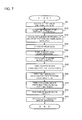
- FIG. 7 is a flowchart showing a control procedure executed by a CPU included in a control unit of the tape printer.
- FIG. 8 is a view showing a second use example of the ribbon.
- FIG. 9 is a plan view showing one example of the printing content of the ribbon in an example where a plurality of short connection print patterns are arranged side by side on a third block.
- FIG. 10 is a plan view showing one example of the printing content of the ribbon in an example where a center print pattern is printed at the center of the ribbon.
- FIG. 11 is a plan view showing another example of the printing content of the ribbon.
- FIG. 12 is an overview diagram in an example employing a network configuration.
- a tape printer 1 is a so-called handy-type tape printer held by a user's hand.
- a housing 6 of the tape printer 1 includes a front cover 6 A providing the printer front and a rear cover 6 B providing the printer rear.
- the rear cover 6 B includes a rear cover body 6 B 1 incorporating a variety of mechanisms, and a removable cover 6 B 2 that is removable from the rear cover body 6 B 1 when loading or unloading a cartridge 31 (see FIG. 3 described later) or a dry battery (not shown).
- a motor housing unit 5 for housing a drive motor (not shown). Further below the motor housing unit 5 is disposed a battery housing unit 9 for housing dry batteries.
- the frame 13 has at its upper portion a discharge slit 24 for discharging the decorative tape 301 (see FIG. 3 described later) to the exterior.
- a roller holder 17 is disposed on the frame 13 at its upper right portion. Behind the roller holder 17 is disposed a plate-shaped synthetic resin plate 25 provided to cover the roller holder 17 .
- the plate 25 has at its upper portion a protrusion insertion port 10 that is an opening.
- the rear cover body 6 B 1 has at its upper end a lock hole 11 and has at its lower end two lock holes 12 .
- the frame 13 has at its substantially central portion a concaved recess 26 for gear.
- a gear (not shown) is provided in the recess 26 for gear, with teeth of the gear are covered with a shielding umbrella portion 114 so as to prevent the teeth from being exposed.
- a rib 30 extends vertically on the right side of the ribbon take-up shaft 14 .
- a heat sink 15 that is a rectangular heat radiation plate is disposed on a right side surface of the rib 30 .
- a roller shaft 20 extends vertically between the rib 30 and the discharge slit 24 .
- a raised portion 27 extends vertically on the left side of the roller shaft 20 . The raised portion 27 is inserted into a recessed portion (not shown) of the cartridge 31 , to thereby position the cartridge 31 in the longitudinal direction.
- a guide holder 40 accommodating therein a cutter holder (not shown) having a cutter blade.
- a rib 42 is formed integrally with the frame 13 .
- the rib 42 is formed on the right side of the discharge slit 24 and extends vertically normal to a planar rear surface of the plate 25 .
- a ribbon take-up spool 57 is rotatably arranged adjacent to the ribbon spool 56 in a diagonally left upward direction.
- the ribbon take-up spool 57 draws the ink ribbon 55 from the ribbon spool 56 and takes up the ink ribbon 55 consumed for print of letters, iconographs, etc.
- the cartridge 31 has on its left upper side a roll 53 for the decorative tape to be printed (which is originally volute-shaped but is shown as a simplified simple circle).
- the roll 53 is a roll of the decorative tape 301 wound around a reel 54 having an axis orthogonal to the longitudinal direction of the tape (normal to the plane of paper of FIG. 3 ).
- the decorative tape 301 is a tape for ribbon (a tape for producing a decorative-purpose's ribbon described later) made of fabric material and is a to-be-printed material with a surface on which the ink ribbon 55 is overlaid for print by thermal transfer of ink.
- the gear for discharge roller is meshed with a gear (not shown) disposed on the front side of the frame 13 so that the discharge roller 192 is rotated by rotation of the gear for discharge roller by power transmitted from the drive motor.
- the discharge roller 192 presses the decorative tape 301 against the feed roller 39 rotatably supported on the roller shaft 20 .
- This allows the decorative tape 301 printed by the thermal head 16 as above to be discharged through a discharge port 59 .
- the subsequent feeding path of the decorative tape 301 is such that the decorative tape 301 is fed by the discharge roller 192 , etc., to be guided to the discharge slit 24 , for discharge to the exterior of the tape printer 1 therethrough.
- the user operates the cut lever 4 so that the decorative tape 301 is cut off by the cutter blade.
- the decorative tape 301 is cut off by the cutter blade.
- FIG. 4 shows a functional configuration of a control system in the tape printer 1 .
- the most feature of this embodiment lies in that, when print is actually applied to the decorative tape 301 to be printed, which is in turn cut off to produce a ribbon R in the above manner, the same design pattern is printed on the vicinity of both ends of the ribbon R so as to be arrayed toward their respective closer ends, whereby print can be done in a print style where line symmetry (mirror image or point symmetry) is established relative to a reference line E 0 (see FIG. 5 ) in the width direction positioned at a center in the longitudinal direction of the ribbon R.
- line symmetry mirror image or point symmetry
- the first block BL 1 , the third block BL 3 , and the second block BL 2 thereamong have print formed thereon, whereas the blank blocks BLs at both ends have no print formed thereon, providing plain white blank regions.
- the lengths of the first block BL 1 , the third block BL 3 , the second block BL 2 along the tape feed direction are set to a first block length L 1 , a third block length L 3 , and a second block length, respectively, while the blank blocks BLs at both ends are set to have a blank block length Ls of the same length (it may be a fixed length or an optionally set length).
- the first block BL 1 has a print array where n (n is an integer not less than 2; the same shall apply hereinafter) end print patterns Ip 1 optionally selected by the user are juxtaposed in the tape feed direction.
- the end print pattern Ip 1 of the shown example is a print pattern image representing a cotyledon that opens toward downstream in the tape feed direction, with its length Lu 1 in the tape feed being set in advance to a specific length (fixed length) of the end print pattern Ip 1 .
- the image of this end print pattern Ip 1 be an image that looks like a naturally continuous design pattern irrespective of juxtaposition of a plurality of images toward the same direction along the tape feed direction.
- the second block BL 2 has a print array where n (equal to the number in the first block BL 1 ) end print reverse patterns Ip 2 are juxtaposed in the tape feed direction, the end print reverse pattern Ip 2 being a mirror image of the end print pattern Ip 1 with respect to the tape feed direction.
- the end print reverse pattern Ip 2 of the shown example is a print pattern image representing a cotyledon that opens toward upstream in the tape feed direction, with its length Lu 2 in the tape feed direction being set to be equal to the length Lu 1 of the end print pattern Ip 1 .
- this end print reverse pattern Ip 2 may be generated by converting the end print pattern Ip 1 .
- the ribbon R can have a print style where apparently the same design patterns are arrayed toward each of upstream and downstream in the tape feed direction.
- connection print pattern Ip 3 representing a stem positioned at a center of cotyledon of the end print pattern Ip 1 (with a unit fixed length Lu 3 in the tape feed direction) and, more specifically, is a straight line positioned at a center in the width direction of the decorative tape 301 and extending along the tape feed direction.
- the connection print pattern Ip 3 printed on the third block BL 3 in this manner is desirably an image with a variable length that can apparently secure a natural connection irrespective of the juxtaposition of the end print patterns Ip 1 and the end print reverse pattern Ip 2 toward upward and downward, respectively and that can apparently keep a natural continuity irrespective of print with any length in the tape feed direction.
- connection print pattern Ip 3 used as the connection print pattern Ip 3 is one that is prepared in advance correspondingly to the selected end print pattern Ip 1 .
- the ROM 530 c stores therein a plurality of types (see FIGS. 9, 10, 11 , etc. described later) of the end print patterns Ip 1 each having the length Lu 1 in the tape feed direction and simultaneously stores therein a plurality of types (see FIGS. 9, 10, 11 , etc. described later) of the connection print patterns Ip 3 each having the unit fixed length Lu 3 .
- the ROM 530 c further stores a pattern association table (not shown) therein. In the pattern association table is stored an optimum combination (one-to-one correspondence) of each end print pattern Ip 1 and each connection print pattern Ip 3 .
- connection print pattern Ip 3 is not limited to the straight line, but it may be of a shape or pattern other than the straight line as long as its single one has a line symmetric shape with respect to the reference line E 3 (see FIG. 5 ) extending in the width direction of the tape.
- the first block BL 1 and the second block BL 2 positioned at both sides, respectively, of the third block BL 3 can each have a print style where apparently the same design patterns are arrayed toward upstream and downstream in the tape feed direction, with a line symmetry across the third block BL 3 .
- FIG. 6 shows a use example of the thus print-formed and produced ribbon R.
- the ribbon R is wound around the periphery of a box B in the shape of a rectangular parallelepiped, with its both ends being tied in so-called bowknot.
- the ribbon is used not only to provide a function to wrap the box B but also as an ornament imparting an enhanced aesthetic appearance to the entirety.
- the both ends of the ribbon R are laterally protrudingly exposed from the knot, but since print is formed on the ribbon R in the print style shown in FIG. 5 with such an arrangement of the both ends, the aesthetic appearance around the bowknot can be improved.
- the CPU 530 a accepts an input of selection of which type of print is to be formed among a plurality of end print patterns Ip 1 with different design patterns prepared in advance (as described above, stored in the ROM 530 c ), based on an operation input from the user via the operating unit 3 .
- the CPU 530 a then refers to the pattern association table of the ROM 530 c , to decide a connection print pattern Ip 3 corresponding to the accepted end print pattern Ip 1 .
- step S 10 the CPU 530 a accepts an input to set the ribbon full length Lr to any length, based on an operation input from the user via the operating unit 3 .
- step 15 where using a specific length Lu 1 corresponding to the end print pattern Ip 1 selected at step S 5 and a ribbon full length Lr set at step S 10 , the CPU 530 a calculates number of prints n of the end print pattern Ip 1 (in other words, number of times of repetition of the end print pattern) in each of the first block BL 1 and the second block BL 2 , and a third block length L 3 (see Eqs. 1 and 2).
- a blank block length Ls may be a predefined length or may separately be input and set to any length by the user.
- step 20 the CPU 530 a generates print data to be printed on the entire ribbon R (i.e., the first block BL 1 , the third block BL 3 positioned upstream of the first block BL 1 along the tape feed direction, and the second block BL 2 positioned upstream of the third block BL 3 along the tape feed direction).
- n end print patterns Ip 1 selected at step S 5 are repeatedly adjacently arrayed along the tape feed direction (in other words, the ribbon length direction).
- the connection print pattern Ip 3 decided correspondingly to the end print pattern Ip 1 at step S 10 is repeated at least one time (although the number of times is one in this example, it may be a plurality of number of times; see FIG. 9 , etc., described later) along the ribbon length direction. If repeated a plurality of number of times, the number of times of repetition is calculated by the CPU 530 a , using the third block length L 3 calculated at step S 15 and the unit fixed length Lu 3 of the connection print pattern Ip 3 .
- end print reverse patterns Ip 2 are repeatedly adjacently arranged along the ribbon length direction (see FIG. 5 , etc.), the end print reverse pattern Ip 2 being generated through conversion of the selected end print pattern Ip 1 into a mirror image reversed along the tape feed direction.
- step S 25 the CPU 530 a starts production of the ribbon R. More specifically, the drive motor is driven to start feed of the decorative tape 301 to be printed.
- step S 30 the CPU 530 a feeds the decorative tape 301 by the blank block length Ls at the downstream end without forming any print.
- step S 35 the CPU 530 a applies print to the first block BL 1 . More specifically, during which the tape is fed through the first block length L 1 (in other words, throughout a region of the decorative tape 301 in which the distance from the print start position exceeds Ls and is not more than L 1 ), the CPU 530 a repeatedly prints the selected end print pattern Ip 1 n consecutive times (the above number of times of repetition) by the thermal head 16 .
- the end print pattern Ip 1 may be repeatedly printed proper integer times not less than 1 and less than n.
- step S 40 the CPU 530 a applies the connection print pattern Ip 3 to the third block BL 3 . More specifically, during which the tape is fed through the third block length L 3 (in other words, throughout a region of the decorative tape 301 in which the distance from the print start position exceeds Ls+L 1 and is not more than Ls+L 1 +L 3 ), the CPU 530 a prints the end print pattern Ip 3 with a variable length prepared correspondingly to the selected end print pattern Ip 1 .
- step S 45 the CPU 530 a applies print to the second block BL 2 . More specifically, during which the tape is fed through the second block length L 2 (in other words, throughout a region of the decorative tape 301 in which the distance from the print start position exceeds Ls+L 1 +L 3 and is not more than Ls+L 1 +L 3 +L 2 ), the CPU 530 a repeatedly prints the selected end print reverse pattern Ip 3 n consecutive times (the above number of times of repetition) by the thermal head 16 .
- step S 50 the CPU 530 a feeds the decorative tape 301 by the blank block length Ls at the upstream end without forming any print.
- step S 55 the CPU 530 a terminates the production of the ribbon R. More specifically, the CPU 530 a stops the drive of the driving motor to cease the feed of the decorative tape 301 to be printed, after which it displays a print completion on the display unit 550 and provides an indication to urge the user to cut off the decorative tape 301 by the operation of the cut lever 4 . Then, this flow terminates.
- a print style can be implemented where in the first block BL 1 and the second block BL 2 positioned at both sides, respectively, of the third block BL 3 apparently the same design patterns are arrayed toward downstream and upstream, respectively, in the tape feed direction, with a line symmetry across the third block BL 3 .
- these first block BL 1 and second block BL 2 including tape both ends, respectively, are line-symmetric with each other, a visually bisymmetric appearance can be applied to the both ends and their respective vicinities of the ribbon R that are protrudingly exposed leftward and rightward from the knot when the user forms a bowknot using the ribbon R produced from this decorative tape 301 to be printed. This contributes to an improved aesthetic appearance of the bowknot.
- a ribbon is produced that has, in the mentioned order, a single first block BL 1 , a single third block BL 3 , and a single second block BL 2 from the downstream end toward the upstream end in the tape feed direction.
- This enables the entire ribbon R to have a line-symmetric print array (the same shall apply to modification examples described later) with respect to the reference line E 0 extending along the tape width direction by a most simple print style.
- the decorative tape 301 is a tape for ribbon made of a fabric material
- a ribbon R with a strength suitable for the usage such as wrapping, packing, bundling, decorating, etc.
- the bowknot is formed after winding the ribbon R around the periphery of the object box B, this is not limitative.
- FIG. 8 also in the use as a paste ribbon for decorative purposes only pasted on the surface of an object B′ with the entire ribbon R being curved and crossed so as to allow the print surfaces of both ends to face frontward, there can be achieved the same effect as the above to improve the visual aesthetic appearance.
- the use style is such that both ends and their respective vicinities of the ribbon R are protrudingly exposed from a predetermined intersection, a visually bisymmetric appearance can be achieved leading to an aesthetic enhancement.
- connection print pattern Ip 3 comprised of one variable-length data that is extendable along the tape feed direction
- the present disclosure is not limited thereto.
- in the third block BL 3 there may be printed adjacently side by side a plurality of connection print patterns Ip 3 each having a sufficiently short unit fixed length Lu 3 in the tape feed direction.
- this connection print pattern Ip 3 also has by itself a line-symmetric style with respect to the reference line E 3 extending along the tape width direction.
- a ribbon R is produced that has a single first block BL 1 , a third block BL 3 on which a plurality of connection print patterns Ip 3 are printed, and a single second block BL 2 in the mentioned order from the downstream end toward the upstream end in the tape feed direction.
- This enables a complicated continuous pattern as in the example shown to be printed on the third block BL 3 as well. If the third block length L 3 is not just the integer multiple of the unit fixed length Lu 3 , the ribbon full length Lu or the blank block length Ls may be finely adjusted.
- the end print pattern Ip 1 printed repeatedly plurality of times is by itself line-symmetric (a mirror image) with respect to the reference line E 1 along the tape width direction. Since in this case the end print pattern Ip 1 printed on the first block BL 1 coincides in image content with the end print reverse pattern Ip 2 printed on the second block BL 2 , there can be omitted a process of converting the end print pattern Ip 1 to generate the end print reverse pattern Ip 2 .
- the above embodiment has only a single third block BL 3 between the first block BL 1 and the second block BL 2 , the present disclosure is not limited thereto.
- the present disclosure is not limited thereto.
- at a center position of the entire ribbon R in the tape longitudinal direction there may be disposed, separate from the connection print pattern Ip 3 printed on the third block BL 3 , a fourth block BL 4 on which is printed a center print pattern Ip 4 that is by itself line-symmetric (a mirror image) with respect to a reference line E 4 along the tape width direction.
- a single center print pattern Ip 4 is configured from a composite of a single end print pattern Ip 1 printed on the first block BL 1 , disposed downstream in the tape feed direction and a single end print reverse pattern Ip 2 printed on the second block BL 2 , disposed upstream adjacent to the end print pattern Ip 1 in the tape feed direction.
- the center print pattern Ip 4 is an image (mirror image) that is by itself line-symmetric with respect to the reference line E 4 along the tape width direction
- 2 ⁇ Lu 1 is the length L 4 in the tape feed direction of the fourth block BL 4 on which a single center print pattern Ip 4 is printed.
- the third block BL 3 of the same length L 3 is interposed between the first block BL 1 and the fourth block BL 4 and between the fourth block BL 4 and the second block BL 2 .
- the print data formed on the decorative tape 301 has the first block BL 1 , the second block BL 2 , the third block BL 3 , and the fourth block BL 4 having the fourth block length L 4 depending on the set and input ribbon full length Lr, the fourth block BL 4 being a line-symmetric image with respect to the reference line E 4 along the tape width direction including the end print pattern Ip 1 toward downstream in the tape feed direction and the end print reverse pattern Ip 2 toward upstream in the tape feed direction.
- the tape printer 1 produces a ribbon R with a ribbon full length Lr on which: using the print data, a single first block BL 1 is formed in a downstream region containing a downstream end in the tape feed direction; a single second block BL 2 is formed in an upstream region containing an upstream end in the tape feed direction; and at least one third block BL 3 and a single fourth block BL 4 are formed between the first block BL 1 and the second block BL 2 .
- a ribbon R is produced that includes, in the mentioned order from the downstream end toward the upstream end in the tape feed direction, the single first block BL 1 , the single third block BL 3 , the single fourth block BL 4 on which the center print pattern Ip 4 is printed, the single third block BL 3 , and the single second block BL 2 .
- an external appearance can be obtained where the same patterns are arrayed in a visually bisymmetric fashion over the substantially full length of the ribbon R with respect to a border, i.e., a center position in the length direction.
- a border i.e., a center position in the length direction.
- the end print pattern Ip 1 of a dotted image may be used as shown in FIG. 11 for example.
- the center print pattern Ip 4 be an image composed of two dots arranged on each of the downstream side and the upstream side in the tape feed direction, line-symmetrically with respect to the reference line E 4 along the tape width direction, and one dot disposed to the center in the tape width direction on the upstream side in the tape feed direction (five dots in total are arranged).
- the fourth block length L 4 of such a center print pattern Ip 4 is a fixed length less than twice of the end print pattern length Lu 1
- the third block length L 3 and the number of times n may be calculated based on the fourth block length L 4 . It is preferred in this case that the connection print pattern Ip 3 of the third block BL 3 be of plain white as shown in the diagram.
- the third block BL 3 can be omitted if the length obtained by subtracting the blank block length Ls at both ends from the ribbon full length Lr (or the length obtained by further subtracting the fourth block length L 4 therefrom) is just the integer multiple of the unit length Lu 1 of the end print pattern Ip 1 .
- the length of the center print pattern Ip 4 in the tape feed direction, i.e., the fourth block length L 4 may be variably set depending on the set and input ribbon full length Lr, similar to the third block BL 3 .
- the center print pattern Ip 4 printed on the fourth block BL 4 may be a pattern type (pattern type not derived from the end print pattern Ip 1 ) other than the shown example as long as it is line-symmetric with respect to the reference line E 4 along the tape width direction.
- pattern type pattern type not derived from the end print pattern Ip 1
- the entire ribbon R is line-symmetric (a mirror image) with respect to the reference line E 0 along the tape width direction, there can be obtained aesthetic appearance putting accent on its center position.
- a network configuration may be employed where a general-purpose PC 600 is in charge of processes of print data compilation and generation and is connected via a proper network NW to a tape printer 1 A that performs only printing on the decorative tape 301 and cutoff thereof.
- a proper memory included in the general-purpose PC 600 stores therein a print data compilation and generation application activated in the general-purpose PC 600 and capable of executing a procedure equivalent to that of FIG. 7 .
- the tape printer 1 A can have a simplified configuration.
Landscapes
- Engineering & Computer Science (AREA)
- General Engineering & Computer Science (AREA)
- Physics & Mathematics (AREA)
- General Physics & Mathematics (AREA)
- Theoretical Computer Science (AREA)
- Printers Characterized By Their Purpose (AREA)
- Record Information Processing For Printing (AREA)
Abstract
Description
Nn=INT((Lr−2×Ls)/(2×Lu1)) (Eq. 1)
Where INT is a function for finding an integer.
L3=Lr−(Ls+L1+L2+Ls)
=Lr−2×(Ls+L1)
=Lr−2×(Ls+n×Lu1) (Eq. 2)
L3=(Lr−(Ls+L1+L4+L2+Ls))/2
=(Lr−2×Ls−2×L1−L4)/2
=(Lr−2×Ls−2×(n+1)×Lu1))/2 (Eq. 3)
The number of times n of repetition of the end print pattern Ip1 and the end print reverse pattern Ip2 on the first block BL1 and the second block BL2, respectively, is found by:
n=INT((Lr−2×Ls−L4)/(2×Lu1))
=INT((Lr−2×Ls−2×Lu1)/(2×Lu1))
=INT((Lr−2×(Ls+Lu1))/(2×Lu1)) (Eq. 4)
Claims (20)
Applications Claiming Priority (2)
| Application Number | Priority Date | Filing Date | Title |
|---|---|---|---|
| JP2014266007A JP6264661B2 (en) | 2014-12-26 | 2014-12-26 | Tape printer and decorative tape creation program |
| JP2014-266007 | 2014-12-26 |
Publications (2)
| Publication Number | Publication Date |
|---|---|
| US20160189013A1 US20160189013A1 (en) | 2016-06-30 |
| US9471854B2 true US9471854B2 (en) | 2016-10-18 |
Family
ID=56164589
Family Applications (1)
| Application Number | Title | Priority Date | Filing Date |
|---|---|---|---|
| US14/870,096 Expired - Fee Related US9471854B2 (en) | 2014-12-26 | 2015-09-30 | Tape printer and recording medium |
Country Status (2)
| Country | Link |
|---|---|
| US (1) | US9471854B2 (en) |
| JP (1) | JP6264661B2 (en) |
Families Citing this family (4)
| Publication number | Priority date | Publication date | Assignee | Title |
|---|---|---|---|---|
| JP6131657B2 (en) * | 2013-03-21 | 2017-05-24 | セイコーエプソン株式会社 | Tape printer |
| JP2016189129A (en) * | 2015-03-30 | 2016-11-04 | セイコーエプソン株式会社 | Ribbon creation method, tape printer and program |
| JP6621332B2 (en) * | 2016-01-14 | 2019-12-18 | セイコーエプソン株式会社 | Ribbon creation method, tape printer, and program |
| JP6880710B2 (en) * | 2016-12-22 | 2021-06-02 | カシオ計算機株式会社 | Printing equipment, printing methods and programs |
Citations (4)
| Publication number | Priority date | Publication date | Assignee | Title |
|---|---|---|---|---|
| JP2004216833A (en) | 2003-01-17 | 2004-08-05 | Seiko Epson Corp | Tape printer and tape cartridge |
| US20090103123A1 (en) * | 2007-10-04 | 2009-04-23 | Tatsuhiro Ikedo | Label data creating apparatus, label data creating method, and computer program product |
| US20140085668A1 (en) * | 2012-09-25 | 2014-03-27 | Brother Kogyo Kabushiki Kaisha | Printer |
| US20150037545A1 (en) * | 2013-07-30 | 2015-02-05 | Brother Kogyo Kabushiki Kaisha | Recording Medium and Recorded Matter |
Family Cites Families (5)
| Publication number | Priority date | Publication date | Assignee | Title |
|---|---|---|---|---|
| JP4665805B2 (en) * | 2006-03-17 | 2011-04-06 | カシオ計算機株式会社 | Printing device |
| US20080175643A1 (en) * | 2007-01-18 | 2008-07-24 | Craig Saunders | Ribbon printer |
| JP2011063905A (en) * | 2009-09-16 | 2011-03-31 | Yachi Seni Kogyo Kk | Ribbon tape with rich decorative property |
| JP6131657B2 (en) * | 2013-03-21 | 2017-05-24 | セイコーエプソン株式会社 | Tape printer |
| JP6041147B2 (en) * | 2013-03-27 | 2016-12-07 | ブラザー工業株式会社 | Printing tape display processing program, tape printer |
-
2014
- 2014-12-26 JP JP2014266007A patent/JP6264661B2/en active Active
-
2015
- 2015-09-30 US US14/870,096 patent/US9471854B2/en not_active Expired - Fee Related
Patent Citations (6)
| Publication number | Priority date | Publication date | Assignee | Title |
|---|---|---|---|---|
| JP2004216833A (en) | 2003-01-17 | 2004-08-05 | Seiko Epson Corp | Tape printer and tape cartridge |
| US20040208682A1 (en) * | 2003-01-17 | 2004-10-21 | Seiko Epson Corporation | Tape printing apparatus and tape cartridge |
| US20050226670A1 (en) * | 2003-01-17 | 2005-10-13 | Seiko Epson Corporation | Tape printing apparatus and tape cartridge |
| US20090103123A1 (en) * | 2007-10-04 | 2009-04-23 | Tatsuhiro Ikedo | Label data creating apparatus, label data creating method, and computer program product |
| US20140085668A1 (en) * | 2012-09-25 | 2014-03-27 | Brother Kogyo Kabushiki Kaisha | Printer |
| US20150037545A1 (en) * | 2013-07-30 | 2015-02-05 | Brother Kogyo Kabushiki Kaisha | Recording Medium and Recorded Matter |
Also Published As
| Publication number | Publication date |
|---|---|
| JP2016124178A (en) | 2016-07-11 |
| US20160189013A1 (en) | 2016-06-30 |
| JP6264661B2 (en) | 2018-01-24 |
Similar Documents
| Publication | Publication Date | Title |
|---|---|---|
| US9471854B2 (en) | Tape printer and recording medium | |
| EP2833255B1 (en) | Print data editing program and printed matter | |
| US20190016161A1 (en) | Printed-matter producing device and medium | |
| JP2012071525A (en) | Tape printing device | |
| JP6164476B2 (en) | Printing device | |
| JP2012254566A (en) | Editing program for creating labels and label-editing device | |
| WO2012132987A1 (en) | Method for controlling printing speed of thermal printhead | |
| US20140362157A1 (en) | Printer and printing method | |
| JP7147549B2 (en) | editor and printer | |
| US20140354751A1 (en) | Printer, Printing Control Program, and Printing Method | |
| JP5104424B2 (en) | Label making device | |
| US9617101B2 (en) | Tape printing device, tape length calculation method, and computer-readable recording medium | |
| TWI659864B (en) | Cassette | |
| JP2015166146A (en) | Printing label preparation device | |
| US20200269611A1 (en) | Printing device configured to, when header part of object to be printed does not match already-printed header part, print header part and body part of object and cut off already-printed header part | |
| JP2016199000A (en) | Label preparation device and label preparation method | |
| JP2014008771A (en) | Thermal printer and program therefor | |
| US20160026419A1 (en) | Image data generation | |
| JP7354612B2 (en) | printing device | |
| JP6423639B2 (en) | Tape printing apparatus and print data generation method | |
| US9821576B2 (en) | Tape printer and recording medium | |
| JP6443164B2 (en) | Print data generation apparatus, print apparatus, print data generation method, and program | |
| JP2013244741A (en) | Printing apparatus | |
| JP2012139953A (en) | Label forming device and control method of label forming device | |
| US10643656B2 (en) | Printing apparatus, method of controlling printing apparatus, and non-transitory recording medium containing computer-readable instructions therefor |
Legal Events
| Date | Code | Title | Description |
|---|---|---|---|
| AS | Assignment |
Owner name: BROTHER KOGYO KABUSHIKI KAISHA, JAPAN Free format text: ASSIGNMENT OF ASSIGNORS INTEREST;ASSIGNOR:SANO, NAKO;REEL/FRAME:036688/0717 Effective date: 20150827 |
|
| STCF | Information on status: patent grant |
Free format text: PATENTED CASE |
|
| MAFP | Maintenance fee payment |
Free format text: PAYMENT OF MAINTENANCE FEE, 4TH YEAR, LARGE ENTITY (ORIGINAL EVENT CODE: M1551); ENTITY STATUS OF PATENT OWNER: LARGE ENTITY Year of fee payment: 4 |
|
| FEPP | Fee payment procedure |
Free format text: MAINTENANCE FEE REMINDER MAILED (ORIGINAL EVENT CODE: REM.); ENTITY STATUS OF PATENT OWNER: LARGE ENTITY |
|
| LAPS | Lapse for failure to pay maintenance fees |
Free format text: PATENT EXPIRED FOR FAILURE TO PAY MAINTENANCE FEES (ORIGINAL EVENT CODE: EXP.); ENTITY STATUS OF PATENT OWNER: LARGE ENTITY |
|
| STCH | Information on status: patent discontinuation |
Free format text: PATENT EXPIRED DUE TO NONPAYMENT OF MAINTENANCE FEES UNDER 37 CFR 1.362 |
|
| FP | Lapsed due to failure to pay maintenance fee |
Effective date: 20241018 |