US9470347B1 - Fluid line connector - Google Patents
Fluid line connector Download PDFInfo
- Publication number
- US9470347B1 US9470347B1 US13/487,509 US201213487509A US9470347B1 US 9470347 B1 US9470347 B1 US 9470347B1 US 201213487509 A US201213487509 A US 201213487509A US 9470347 B1 US9470347 B1 US 9470347B1
- Authority
- US
- United States
- Prior art keywords
- main body
- ferrule
- connector
- fluid
- conduit
- Prior art date
- Legal status (The legal status is an assumption and is not a legal conclusion. Google has not performed a legal analysis and makes no representation as to the accuracy of the status listed.)
- Active, expires
Links
Images


Classifications
-
- F—MECHANICAL ENGINEERING; LIGHTING; HEATING; WEAPONS; BLASTING
- F16—ENGINEERING ELEMENTS AND UNITS; GENERAL MEASURES FOR PRODUCING AND MAINTAINING EFFECTIVE FUNCTIONING OF MACHINES OR INSTALLATIONS; THERMAL INSULATION IN GENERAL
- F16L—PIPES; JOINTS OR FITTINGS FOR PIPES; SUPPORTS FOR PIPES, CABLES OR PROTECTIVE TUBING; MEANS FOR THERMAL INSULATION IN GENERAL
- F16L33/00—Arrangements for connecting hoses to rigid members; Rigid hose-connectors, i.e. single members engaging both hoses
- F16L33/20—Undivided rings, sleeves, or like members contracted on the hose or expanded inside the hose by means of tools; Arrangements using such members
- F16L33/207—Undivided rings, sleeves, or like members contracted on the hose or expanded inside the hose by means of tools; Arrangements using such members only a sleeve being contracted on the hose
- F16L33/2071—Undivided rings, sleeves, or like members contracted on the hose or expanded inside the hose by means of tools; Arrangements using such members only a sleeve being contracted on the hose the sleeve being a separate connecting member
-
- F—MECHANICAL ENGINEERING; LIGHTING; HEATING; WEAPONS; BLASTING
- F16—ENGINEERING ELEMENTS AND UNITS; GENERAL MEASURES FOR PRODUCING AND MAINTAINING EFFECTIVE FUNCTIONING OF MACHINES OR INSTALLATIONS; THERMAL INSULATION IN GENERAL
- F16L—PIPES; JOINTS OR FITTINGS FOR PIPES; SUPPORTS FOR PIPES, CABLES OR PROTECTIVE TUBING; MEANS FOR THERMAL INSULATION IN GENERAL
- F16L19/00—Joints in which sealing surfaces are pressed together by means of a member, e.g. a swivel nut, screwed on, or into, one of the joint parts
- F16L19/08—Joints in which sealing surfaces are pressed together by means of a member, e.g. a swivel nut, screwed on, or into, one of the joint parts with metal rings which bite into the wall of the pipe
- F16L19/10—Joints in which sealing surfaces are pressed together by means of a member, e.g. a swivel nut, screwed on, or into, one of the joint parts with metal rings which bite into the wall of the pipe the profile of the ring being altered
-
- F—MECHANICAL ENGINEERING; LIGHTING; HEATING; WEAPONS; BLASTING
- F16—ENGINEERING ELEMENTS AND UNITS; GENERAL MEASURES FOR PRODUCING AND MAINTAINING EFFECTIVE FUNCTIONING OF MACHINES OR INSTALLATIONS; THERMAL INSULATION IN GENERAL
- F16L—PIPES; JOINTS OR FITTINGS FOR PIPES; SUPPORTS FOR PIPES, CABLES OR PROTECTIVE TUBING; MEANS FOR THERMAL INSULATION IN GENERAL
- F16L33/00—Arrangements for connecting hoses to rigid members; Rigid hose-connectors, i.e. single members engaging both hoses
- F16L33/22—Arrangements for connecting hoses to rigid members; Rigid hose-connectors, i.e. single members engaging both hoses with means not mentioned in the preceding groups for gripping the hose between inner and outer parts
- F16L33/223—Arrangements for connecting hoses to rigid members; Rigid hose-connectors, i.e. single members engaging both hoses with means not mentioned in the preceding groups for gripping the hose between inner and outer parts the sealing surfaces being pressed together by means of a member, e.g. a swivel nut, screwed on or into one of the joint parts
- F16L33/224—Arrangements for connecting hoses to rigid members; Rigid hose-connectors, i.e. single members engaging both hoses with means not mentioned in the preceding groups for gripping the hose between inner and outer parts the sealing surfaces being pressed together by means of a member, e.g. a swivel nut, screwed on or into one of the joint parts a clamping ring being arranged between the threaded member and the connecting member
Definitions
- the present invention relates generally to couplers or connectors for attaching the ends of fluid lines to one another or to other fluid couplings.
- Fluid lines, conduits, hoses, and the like are commonly used for conveying vehicular fluids from one portion of a vehicle to another.
- Such conduits may be associated with fuel, engine and transmission oils and other lubricants, power steering fluid, coolants or refrigerants, hydraulic brake fluid, shock absorber fluid, ride height control fluid, and the like.
- fluid lines require repair, such as due to pinhole leaks, cracks, impact damage, or the like, it is generally desirable and significantly faster and more economical to repair the damaged section rather than replace the entire fluid line. Because many such fluid lines operate at elevated fluid pressures, it is desirable for fluid line couplers or other repair devices to provide secure and sealed repair of a damaged fluid line, so that the repaired fluid line can be returned to normal service.
- the present invention provides a fluid line connector for use in repairing fluid conduits, which are typically rigid or semi-rigid fluid lines, such as typically found on vehicles.
- the fluid line connectors may be used to repair or replace damaged sections of fuel lines, oil lines, air conditioner refrigerant lines, or the like, or may be used as a fluid line fitting or portion of a fitting for coupling a fluid line to another fluid conduit.
- the fluid line connector of the present invention includes a main body with a profiled or varying-diameter inner surface that defines a fluid passageway.
- the profiled inner surface defines a series of circular stepped regions that allow the fluid line connector to be adapted for use on fluid lines of different diameters or sizes.
- An annular ferrule is partially positioned in an open end of the main body, and at least a portion of the ferrule is radially compressible to engage or impinge on the outer surface of a fluid line that is positioned in the fluid passageway of the main body.
- the fluid line is typically urged into abutment with one of the stepped regions prior to compressing the ferrule.
- An annular conduit coupler is attached to an outer surface of the main body, and has an inner surface that engages the ferrule to bias or urge the ferrule inwardly relative to the main body as the coupler is moved or tightened onto the body. This movement of the ferrule results in compression of the flexible portion of the ferrule due to engagement of corresponding ramped surfaces of the ferrule and the main body.
- the conduit coupler By tightening the conduit coupler with a fluid line positioned in the main body, the ferrule is compressed into tight engagement with the fluid line, which helps secure the fluid line in the main body.
- the fluid line connector may comprise a double-ended connector, such that two fluid lines having the same or different diameters may be coupled to one another using a single fluid line connector.
- the outer surface of the connector's main body includes a threaded outer portion
- the inner surface of the conduit coupler includes a threaded inner portion corresponding to the outer threaded portion of the main body, so that the conduit coupler and the ferrule are axially movable together relative to the main body via rotation of the conduit coupler about the threaded body.
- the inner surface of the main body includes a seal-receiving portion for receiving an annular seal in an annular space defined between the inner surface of the main body and the outer surface of the fluid line.
- the ferrule may include a plurality of longitudinal slots in a circumferentially-spaced arrangement, to facilitate radial compression of the ferrule.
- the ferrule may further include a radially inwardly-directed annular shoulder at its compressible portion, for impinging on the outer surface of the fluid conduit, which enhances the ferrule's ability to secure the conduit or fluid line in the body of the connector.
- the fluid line connector of the present invention provides for the secure repair of damaged fluid lines, such as those that may be found on a vehicle.
- the connector is adaptable for use on fluid lines of different diameters, and can also be used for connecting the ends of fluid lines to other couplings or fluid conduits.
- the present invention can provide a low-cost, easy-to-install, and leak-resistant repair, which resists inadvertent pull-out of the fluid line from the connector.
- FIG. 1 is a perspective view of a fluid line connector in accordance with the present invention
- FIG. 2 is an end elevation of the fluid line connector of FIG. 1 ;
- FIG. 3 is a side sectional view of the fluid line connector, taken along line III-III of FIG. 2 ;
- FIG. 4 is an enlarged side and partial sectional view of an end portion of the fluid line connector, shown without a conduit coupler;
- FIG. 5 is a perspective view of a main body of the fluid line connector
- FIG. 6 is an end elevation of the main body
- FIG. 7 is a side sectional view of the main body, taken along line VII-VII of FIG. 6 ;
- FIG. 8 is a side elevation of a ferrule of the fluid line connector
- FIG. 9 is a side sectional elevation of the ferrule
- FIG. 10 is a perspective view of a conduit coupler of the fluid line connector
- FIG. 11 is an end elevation of the conduit coupler
- FIG. 12 is a side sectional elevation of the conduit coupler
- FIG. 13 is a perspective view of another fluid line connector in accordance with the present invention.
- FIG. 14 an end elevation of the fluid line connector of FIG. 13 ;
- FIG. 15 is a side sectional view of the fluid line connector, taken along line XV-XV of FIG. 14 ;
- FIG. 16 is a perspective view of a main body of the fluid line connector of FIG. 13 ;
- FIG. 17 is a side sectional view of the main body.
- FIG. 18 is a perspective view of a crimping element for the fluid line connector of FIG. 13 .
- a fluid line connector 10 is provided for the secure coupling of respective ends of fluid lines or conduits 12 a , 12 b ( FIGS. 1 and 3 ).
- the two fluid lines 12 a , 12 b may be formed from a single fluid line that was cut to remove a damaged section of the line.
- fluid line connector 10 is symmetrical about a lateral axis or a plane that passes through a main body 14 at a central gripping portion 16 (which may typically have a non-circular outer surface, such as a hexagonal shape as shown). Referring to FIG.
- fluid line connector 10 has a longitudinal central axis 18 along which a fluid passageway 20 is defined through the connector ( FIGS. 2 and 3 ).
- Two ferrules 22 a , 22 b are positioned on respective sides of main body 14 , and a conduit coupler or collar 24 a , 24 b couples the respective ferrules 22 a , 22 b to main body 14 , to secure fluid lines 12 a , 12 b in fluid line connector 10 , as will be described in more detail below.
- Main body 14 includes a pair of hollow cylindrical end portions 26 a , 26 b ( FIGS. 5 and 7 ), each defining a portion of fluid passageway 20 .
- Each end portion 26 a , 26 b has an outboard open end 28 a , 28 b for receiving a respective one of fluid lines 12 a , 12 b .
- End portions 26 a , 26 b have threaded outer surfaces 30 a , 30 b for engaging conduit couplers 24 a , 24 b , and further have profiled or shaped or ramped (i.e. varying-diameter) inner surfaces 32 a , 32 b .
- the profiled or shaped inner surfaces 32 a , 32 b each include a ramped surface or portion 34 that is generally frusto-conical in shape with a maximum inner diameter at its outboard end (i.e., at open outboard ends 28 a , 28 b ), and a minimum inner diameter at its inboard end.
- a lip or shoulder 36 Located further inboard from ramped outer portion 34 is a lip or shoulder 36 that transitions from the inboard ends of ramped outer portion 34 to a seal-receiving portion 38 with a substantially constant inner diameter.
- Seal-receiving portions 38 of inner surfaces 32 a , 32 b provide an annular space between inner surface 32 and the outer surface of a fluid line, such as fluid line 12 a ( FIG. 7 ).
- This annular space receives a resilient annular seal 46 ( FIG. 3 ), which has an inner diameter generally corresponding to the outer diameter of the fluid line 12 a , and an outer diameter generally corresponding to the inner diameter of inner surface 32 at seal-receiving portion 38 .
- annular seal 46 may be dimensioned to have, in its relaxed state, a slightly smaller inner diameter than the outer diameter of the fluid line 12 a , to have a slightly larger outer diameter than seal-receiving portion 38 , so that annular seal 46 is at least slightly compressed between the outer surface of fluid line 12 a and the inner surface of seal-receiving portion 38 .
- annular seal 46 ′ having a smaller inner diameter is used to fill the extra space between seal-receiving portion 38 and the outer surface of the smaller fluid line 12 a′.
- the main body 14 may be formed to engage and partially retain the ends of fluid lines having selected diameters.
- the main body 14 located further inboard from seal-receiving portion 38 are a series of stepped regions 40 a , 40 b , 40 c , with each stepped region having a diameter that is less than the diameter of the stopped region located immediately outboard thereof.
- an outboard stepped region 40 a is immediately adjacent seal-receiving portion 38 , and has a smaller diameter than the seal-receiving portion, while a middle stepped region 40 b (located immediately inboard of outboard stepped portion 40 a ) has a still smaller inner diameter, and an inboard stepped portion 40 c (located immediately inboard of middle stepped region 40 b ) has a still smaller inner diameter.
- the diameters of each stepped portion 40 a - c may correspond to a standard fluid line size, so that main body 14 can be used to join multiple different sizes of tubing or fluid lines.
- the main body 14 includes a constant-diameter inner or central portion or passageway 42 located immediately between the two inboard stepped regions 40 c of the respective end portions 26 a , 26 b ( FIGS. 6 and 7 ).
- Stepped regions 40 a - c define respective annular shoulder regions 44 a - c that provide an abutment or stop surface for a given size (outer diameter) of fluid line, while central portion or passageway 42 allows for fluid flow through the body between the inserted fluid lines.
- fluid lines 12 a and 12 b have relatively large outer diameters that correspond to the annular shoulder regions 44 a defined between outboard stepped region 40 a and middle stepped region 40 b , and in the illustrated embodiment of FIG. 4 , another fluid line 12 a ′ has a smaller diameter that corresponds to the diameter of middle stepped portion 40 b , so that fluid line 12 a ′ lies in abutment with annular shoulder region 44 b .
- the main body can be readily adapted for different sized tubes or lines via selection of an appropriate sized resilient seal 46 and appropriate ferrule 22 .
- Ferrules 22 a , 22 b are identical to one another in the illustrated embodiment, and therefore are referred to generally with reference numeral 22 , as in FIGS. 8 and 9 .
- ferrule 22 has a generally annular shape.
- Each ferrule 22 includes an outboard head portion 48 that remains outboard of the respective outboard ends 28 a , 28 b of main body 14 the when the ferrules are installed at the main body 14 .
- Ferrule 22 further includes a resilient or flexible inboard portion 50 , which extends through the open outboard ends 28 a , 28 b and at least partially along the ramped portion 34 of the profiled or shaped inner surface 32 of main body 14 .
- Flexible inboard portion 50 of ferrule 22 is radially inwardly compressible due to a plurality of longitudinal slots 52 that are formed at least partially along flexible inboard portion 50 and terminate near outboard head portion 48 .
- flexible inboard portion 50 includes a ramped or generally frusto-conical outer surface 54 that generally corresponds to the shape of ramped outer portion 34 of the inner surface 32 of main body 14 , such as shown in FIGS. 3 and 4 .
- Ferrule 22 has an inner surface 56 that defines a generally constant inner diameter when in its relaxed (i.e., uncompressed or unconstricted) configuration ( FIG. 9 ).
- Flexible inboard portion 50 of ferrule 22 includes, at its inboard end portion (i.e., opposite outboard head portion 48 ) a radially inwardly-projecting shoulder or lip 58 , which has a smaller diameter than the rest of inner surface 56 .
- This shoulder or lip 58 enhances the ability of ferrule 22 to impinge or engage or bite into the outer surface of a fluid line in order, to more securely retain the fluid line at the fluid line connector 10 in a manner that will be more fully described below.
- the diameter of inner surface 56 may generally correspond to the outer diameter of the fluid line that the ferrule is configured to engage, while the inner diameter of the shoulder or lip 58 may even more closely correspond to the outer diameter of the fluid line, and preferably may have a slightly smaller diameter than the fluid line to provide an interference fit, for example.
- the shoulder or lip may provide a generally flat engaging surface (such as shown in FIG. 9 ), or may comprise a pointed circumferential tooth that bites into the tube or line as the ferrule is compressed around the tube or line.
- the ferrule may comprise multiple lips or teeth disposed along the inner surface 56 to bite into the tube or line at multiple locations to further enhance retention of the tube or line in the connector.
- a plurality of teeth or threads may be established at the inner surface and along or substantially along the length of the ferrule. Such a configuration would allow the ferrule to bite into the tube along the portion of the tube within the ferrule (and the tube may be threaded into the ferrule before tightening or clamping the ferrule onto the tube).
- the lip or tooth or teeth or threads of the ferrule may slightly bite into the outer surface of the tube when the coupler is tightened, such as by penetrating the outer surface of the tube by about 0.002 inches or more, such as, for example, about 0.003 inches to about 0.005 inches, preferably around the circumference of the tube, and optionally longitudinally along a portion of the tube as well.
- the lip or tooth or teeth of the ferrule thus bite into the tube to enhance retention of the tube in the connector, without piercing the tube wall.
- Outboard head portion 48 of ferrule 22 includes a lip or shoulder 60 having a greater diameter than the ramp outer surface 54 of flexible inboard portion 50 .
- Shoulder 60 can act as a stop surface by contacting the respective end portion 26 a , 26 b of main body 14 at the open outboard ends 28 a , 28 b thereof.
- Outboard head portion 48 further includes a ramped or frusto-conical outboard outer surface 62 that is engaged by the conduit coupler 24 , so that the ferrule 22 can be urged or biased inwardly into one of the end portions 26 a , 26 b of main body 14 , as discussed below.
- Conduit couplers or collars 24 a , 24 b are substantially identical to one another, and therefore are referred to generally with reference numeral 24 , as in FIGS. 10-12 .
- Conduit coupler 24 includes an inner surface 64 having an inboard threaded region 66 , with an inner diameter that generally corresponds to the outer diameter of threaded outer surfaces 30 of main body 14 ( FIG. 12 ).
- Inboard threaded region 66 is configured to threadedly engage threaded outer surface 30 of main body 14 , so that rotation of conduit coupler 24 relative to main body 14 causes the conduit coupler 24 to translate longitudinally along the longitudinal central axis 18 .
- inner surface 64 has an inner diameter that generally corresponds to the outer diameter of the fluid line 12 , which is less than the inner diameter of inner surface 64 at inboard threaded region 66 .
- a ramped or frusto-conical surface portion 70 transitions between the larger inboard threaded region 66 and the smaller outboard surface portion 68 ( FIG. 12 ).
- the ramped inner surface portion 70 of inner surface 64 generally corresponds to the ramped outer surface 62 of the outboard head portion 48 of ferrule 22 , so that these ramped surfaces engage one another as shown in FIG.
- conduit coupler 24 to be used to urge or bias the corresponding ferrule 22 inwardly relative to main body 14 , along the longitudinal axis 18 .
- An annular channel 72 is established between ramped surface portion 70 and inboard threaded portion 66 , and provides a space at the end of the threaded portion 66 to limit or substantially preclude bottoming out of the coupler onto the threaded end portion of the body.
- Conduit coupler 24 further includes an outer surface 74 having a non-circular gripping portion, such as the hexagonal gripping portion shown in the figures, to facilitate turning or rotating the coupler relative to the main body to tighten or loosen the coupler.
- shoulder 60 is spaced outboard of the outer end of the respective end portion 26 a , 26 b ( FIG. 3 ). This space permits longitudinal repositioning or adjustment of ferrule in end portion 26 a or 26 b of main body 14 , and as long as there is a space between shoulder 60 and the outer end of the respective end portion 26 a , 26 b , ferrule 22 can be further tightened into engagement with the fluid line. It will also be observed, with reference to FIG. 3 , that when ferrule 22 is installed, its inboard end (i.e.
- the space between the inboard end of ferrule 22 and seal 46 may be approximately equal to (or slightly larger than) the space between the ferrule shoulder 60 and the outer end of the respective end portion 26 a , 26 b of main body 14 , so that conduit coupler 24 cannot be tightened so far as to cause the ferrule's inboard end to contact or compress the seal 46 .
- ferrule's dimensions could be altered to achieve this, such as by shifting the shoulder 60 outboard or lengthening the flexible inboard portion 50 of the ferrule.
- fluid line connector 10 may be readily assembled from relatively few parts to secure and seal the ends of two fluid lines 12 a , 12 b , and may be adapted to secure different sizes of fluid lines without need for all different connector components.
- fluid line connector 10 is substantially pre-assembled, including installation of the annular seals 46 and the ferrules 22 a , 22 b in the main body 14 , and at least loosely attaching the conduit couplers 24 to the end portions 26 a , 26 b of the main body 14 , prior to the installation of fluid lines 12 a , 12 b .
- the order or method of assembly can be varied, such as by first installing the conduit couplers 24 a , 24 b onto respective fluid lines 12 a , 12 b , followed by installing the respective ferrule 22 a , 22 b and annular seals 46 onto the fluid lines.
- the ferrules and conduit couplers can be at least temporarily retained on the ends of the fluid lines by the annular seals, which are themselves retained on the line ends by a friction or interference fit, prior to attachment with the main body 14 .
- the fluid lines 12 a , 12 b may then be inserted into the respective end portions 26 a , 26 b of the main body, as shown in FIG. 3 .
- Each fluid line 12 a , 12 b is typically urged fully into the main body 14 , until the end of each fluid line abuts a corresponding one of the stepped regions 40 a - c (such as outboard stepped region 40 a as shown in FIG. 3 ) with the seals 46 seated between fluid lines 12 a , 12 b and seal-receiving regions 38 of the main body's inner surface 32 .
- Each conduit coupler 24 a , 24 b may then be threaded onto the end portions 26 a , 26 b of main body and then rotated, causing the conduit couplers 24 a , 24 b to move longitudinally toward central gripping portion 16 due to engagement of the respective threads 30 , 66 of conduit couplers 24 and end portions 26 a , 26 b.
- the non-circular central gripping portion 16 of main body 14 , and the non-circular portions of outer surfaces 74 of the conduit couplers 24 facilitate the use of a wrench or other tool to rotate the conduit couplers on the main body.
- couplers 24 a and 24 b may be rotated simultaneously for faster coupling of the fluid lines 12 a , 12 b , by simultaneously gripping their outer surfaces 74 with respective wrenches or other gripping tools, and rotating them in opposite directions (i.e., without need for gripping the central gripping portion 16 of main body 14 ). This allows equal torque to be applied simultaneously to each conduit coupler 24 a , 24 b so that the conduit couplers can be tightened more or less simultaneously.
- each conduit coupler 24 As each conduit coupler 24 is tightened, its ramped inner surface portion 70 engages the ramped outer surface portion 62 of ferrule 22 to urge the ferrule's flexible inboard portion 50 further into the respective end portion 26 a , 26 b of main body 14 . This causes the ferrule's ramped outer surface 54 to slide along the ramped inner surface portion 34 of the respective end portion 26 a or 26 b of main body 14 .
- each conduit coupler 24 causes the flexible inboard portion 50 of the ferrule 22 (including the inboard shoulder or lip 58 ) to compress or impinge against the outer surface of the fluid line, which results in the fluid line being securely retained in the respective end portion 26 a or 26 b of main body 14 .
- each fluid line 12 a , 12 b is substantially sealed against leakage by a frictional or interference fit above annular seal 46 .
- a glue or sealant such as anaerobic glue or the like, may be applied to the threads 30 and 66 , to retain and further seal the conduit couplers 24 a , 24 b at the respective end portions 26 a , 26 b of main body 14 . This may provide a more permanent junction along the fluid line.
- the corresponding conduit coupler 24 a or 24 b may simply be rotated to loosen the conduit coupler and allow the respective ferrule 22 a or 22 b to move longitudinally outwardly from the end portion 26 a or 26 b of main body 14 .
- the resilience of flexible inboard portion 50 of the ferrule 22 causes the flexible inboard portion to expand outwardly when it is not held in place by the conduit coupler 24 , which relieves its impingement or compression against the outer surface of the fluid line 12 a or 12 b so that the fluid line may be removed from main body 14 , although the fluid line may still be at least frictionally retained in the fluid passageway 20 by annular seal 46 .
- Fluid line connector 10 is a double-ended connector typically used for joining two fluid lines of equal diameter, but it will be appreciated that the same main body 14 can be used for joining two fluid lines of different diameters.
- a seal having a smaller inner diameter such as seal 46
- a different-sized ferrule and conduit coupler can be provided, along with a different-sized ferrule and conduit coupler.
- a ferrule for smaller-diameter fluid lines would typically have a reduced inner diameter as compared to that of ferrule 22 , and the corresponding conduit coupler would also have a reduced inner diameter in its outboard regions (but not including the inboard threaded region 66 , which would remain the same).
- the smaller diameter ferrule and conduit couplers, along with a seal having a smaller inner diameter, would allow the connector to accommodate the smaller-diameter fluid line 12 a ′, or another (smaller) fluid line.
- fluid line connectors 10 can be adapted for use with different sizes of fluid lines, without requiring different main bodies.
- main body 14 may be a more costly component of the fluid line connector, and there may be a significant cost advantage in manufacturing a larger volume of slightly more complex main bodies (i.e., those able to accommodate different sized fluid lines) as compared to manufacturing smaller volumes of several different (and perhaps slightly less complex) main bodies that each are sized to fit only one fluid line size.
- fluid line connector 10 configured to receive different sizes of fluid lines
- only the simpler and less costly annular seal 46 , ferrule 22 , and conduit coupler 24 would be manufactured in different sizes to correspond to the different sizes of fluid lines.
- This adaptability of the main body can also allow fluid line connectors to be packaged as a kit that can accommodate multiple sizes of fluid lines, or to be packaged as a fluid line connector for a single size of fluid line, as desired, with each kit or package including the same main bodies 14 .
- the fluid line connector of the present invention may have a body with one threaded end and coupler and ferrule as discussed above for connecting to one tube end, with the other end of the connector configured for being inserted into another tube end and sealed or retained thereat via other suitable retention means.
- suitable retention means for example, and with reference to FIGS.
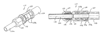
- a fluid line connector 110 for the secure coupling of respective ends of fluid lines or conduits 112 a , 112 b has a longitudinal central axis 118 along which a fluid passageway 120 is defined through the connector, with one end 126 of the body 114 being threaded for retaining the tube end 112 a via a ferrule 122 and a conduit coupler or collar 124 and seal 146 , such as in a similar manner as discussed above.
- the other end 127 of the body 114 is configured to be received in the other tube or conduit 112 b , and may be retained therein via a clamping or crimping element 128 .
- end 126 of body 114 and the ferrule 122 and conduit coupler 124 and seal 146 of connector 110 may be substantially similar to the correspondingly named components of fluid line connector 10 , discussed above, such that a detailed discussion of these aspects of the connectors need not be repeated herein.
- the end 127 of body 114 has a non-uniform diameter so that there are larger diameter portions 127 a and smaller diameter portions 127 b .
- the crimping element 128 is disposed at the end 127 of body 114 and crimping bands 128 a ( FIG. 13 ) are crimped or compressed generally at the smaller diameter portions 127 b to substantially retain and seal the tube 112 b at the end 127 of body 114 .
- crimping bands 128 a FIG. 13
- the body end 127 may include a plurality of ridges or grooves 127 c established therearound and at the larger diameter portions 127 a and/or smaller diameter portions 127 b to bite into the inner surface of the tube 112 b to assist in retaining the tube at the body end 127 when the crimping elements 128 , 128 a are disposed at the body end and crimped thereat.
- the diameter of the fluid passageway 120 is generally the same at the tube end 112 a and at the body end 127 (such that the tube 112 b is larger in diameter than the tube 112 a ). If a smaller diameter tube were inserted into the body (for attachment/connection via the ferrule and coupler), it may be desirable to use a body having a smaller diameter end that is received in the other tube, so that the fluid passageway remains generally constant through the fluid line connector.
- the threaded and tapered end of the bodies may remain generally constant for some sizes of tubes, while the crimping end of the body may vary depending on the particular application of the fluid line connector.
- the threaded and tapered end of the bodies may also vary to accommodate all sizes or diameters of fluid lines over a range of fluid line connectors.
- the present invention provides a fluid line connector that may be used to repair or replace sections of vehicle fluid lines, such as refrigerant lines, oil lines, fuel lines, and the like, while avoiding the complete replacement of fluid lines, which can be very costly and time consuming.
- repairs to small damaged portions of fluid lines may be accomplished simply by cutting out the small damaged portion of a fluid line and joining the exposed open ends of the fluid line with a single fluid line connector.
- Larger damaged portions of a fluid line may be repaired, for example, by cutting out the larger damaged portion of the line, obtaining a replacement line section having a length and shape that generally corresponds to the removed section, and grafting the replacement line section into place using two fluid line connectors, one at each end of the replacement line.
- the fluid line connector may be used to join different sizes of fluid lines, including the option of joining a larger fluid line to a smaller fluid line, if desired.
- the fluid line connector of the present invention is suitable for use in repairing or connecting A/C lines in a vehicle, which flow low-pressure fluid therethrough.
- the toothed configuration of the ferrule provides greater retention of the fluid lines in the connector, such that the connector may be suitable for use in repairing or connecting higher pressure lines of a vehicle or other applications.
Landscapes
- Engineering & Computer Science (AREA)
- General Engineering & Computer Science (AREA)
- Mechanical Engineering (AREA)
- Quick-Acting Or Multi-Walled Pipe Joints (AREA)
Abstract
Description
Claims (13)
Priority Applications (1)
| Application Number | Priority Date | Filing Date | Title |
|---|---|---|---|
| US13/487,509 US9470347B1 (en) | 2011-06-08 | 2012-06-04 | Fluid line connector |
Applications Claiming Priority (2)
| Application Number | Priority Date | Filing Date | Title |
|---|---|---|---|
| US201161494575P | 2011-06-08 | 2011-06-08 | |
| US13/487,509 US9470347B1 (en) | 2011-06-08 | 2012-06-04 | Fluid line connector |
Publications (1)
| Publication Number | Publication Date |
|---|---|
| US9470347B1 true US9470347B1 (en) | 2016-10-18 |
Family
ID=57120248
Family Applications (1)
| Application Number | Title | Priority Date | Filing Date |
|---|---|---|---|
| US13/487,509 Active 2034-12-26 US9470347B1 (en) | 2011-06-08 | 2012-06-04 | Fluid line connector |
Country Status (1)
| Country | Link |
|---|---|
| US (1) | US9470347B1 (en) |
Cited By (6)
| Publication number | Priority date | Publication date | Assignee | Title |
|---|---|---|---|---|
| US20160001346A1 (en) * | 2012-12-14 | 2016-01-07 | Ssp Fittings Corp. | System including cartridge, cartridge fee system, pre-swaging assembly, tube bender, cutting and deburring station, and air blower/vacuum chip collector |
| US20160325551A1 (en) * | 2014-01-20 | 2016-11-10 | Seiko Epson Corporation | Liquid supply device and ink-jet printer |
| US20200318766A1 (en) * | 2008-06-09 | 2020-10-08 | Trinity Bay Equipment Holdings, LLC | Flexible pipe joint |
| CN112204290A (en) * | 2018-04-06 | 2021-01-08 | 布莱恩·B·金 | Assembly equipment for making connecting pipes and finely adjusting the position of the pipes |
| US11396963B2 (en) * | 2018-01-29 | 2022-07-26 | Brian B. Scott | Device for making plumbing connections and a method of use thereof |
| US20240117905A1 (en) * | 2022-10-11 | 2024-04-11 | The Ford Meter Box Company, Inc. | Wide Range Coupling Assembly |
Citations (26)
| Publication number | Priority date | Publication date | Assignee | Title |
|---|---|---|---|---|
| US2727763A (en) * | 1950-05-29 | 1955-12-20 | Michel Bergman | Pipe connector for threadless pipe |
| US3134615A (en) | 1960-10-24 | 1964-05-26 | Crawford Fitting Co | Tube fitting for large diameter tubing |
| US3290069A (en) | 1964-09-03 | 1966-12-06 | Imp Eastman Corp | Tube fitting |
| US3474519A (en) | 1966-11-08 | 1969-10-28 | Boeing Co | Method of making a tube fitting |
| US3649050A (en) | 1970-06-15 | 1972-03-14 | George V Woodling | Tube fitting connection |
| US3659881A (en) * | 1970-03-02 | 1972-05-02 | Seabek Products Inc | Coupling connector |
| US3830532A (en) | 1972-07-07 | 1974-08-20 | Aeroquip Corp | Compression type tube end connection |
| US3923323A (en) | 1974-01-02 | 1975-12-02 | Imp Eastman Corp | Tube fitting |
| US4627644A (en) | 1982-08-27 | 1986-12-09 | Ekman K R | Arrangement for a push-in coupling |
| US4705302A (en) | 1986-05-28 | 1987-11-10 | Teledyne Linair Engineering | Tube fitting |
| US5028078A (en) | 1990-02-05 | 1991-07-02 | The Pullman Company | Tube fitting with variable tube insertion |
| US5551735A (en) | 1993-06-14 | 1996-09-03 | Tokai Rubber Industries, Ltd. | Tube fitting |
| US5655796A (en) | 1992-09-21 | 1997-08-12 | Proprietary Technology, Inc. | Tubular assembly and method of making same |
| US5934714A (en) | 1996-02-28 | 1999-08-10 | Sugiyama Shoji Co., Ltd. | Tube fitting assembly |
| USD461545S1 (en) | 1999-11-22 | 2002-08-13 | Nippon Pillar Packing Co., Ltd. | Sleeve for tube fitting |
| US20040041399A1 (en) * | 2002-08-29 | 2004-03-04 | David Chelchowski | Coupling device for polymeric pipes |
| US6938437B2 (en) | 2003-06-17 | 2005-09-06 | A-1 Components Corporation | Cylindrical seal for refrigerant tube connector |
| US20060049632A1 (en) | 2001-02-06 | 2006-03-09 | Williams Peter C | Tube fitting for stainless steel tubing |
| US7108288B2 (en) | 2001-02-06 | 2006-09-19 | Swagelok Company | Tube fitting with separable tube gripping ring |
| US20060273581A1 (en) | 1997-04-15 | 2006-12-07 | Swagelok Company | Tube fitting with ferrule having recess |
| US20070164563A1 (en) | 2006-01-13 | 2007-07-19 | Arstein Dale C | Fitting for tube or pipe |
| US20080048441A1 (en) | 2001-02-06 | 2008-02-28 | Swagelok Company | Tube fitting with separable tube gripping device |
| US7350828B2 (en) | 2002-09-18 | 2008-04-01 | Swagelok Company | Tube fitting with sealant |
| US20100133812A1 (en) | 2005-06-27 | 2010-06-03 | Swagelok Company | Tube Fitting |
| US20100140928A1 (en) | 2007-01-30 | 2010-06-10 | Aaron Becker | Fluid line connector |
| US20100194107A1 (en) | 2007-08-09 | 2010-08-05 | Swagelok Company | Tube fitting |
-
2012
- 2012-06-04 US US13/487,509 patent/US9470347B1/en active Active
Patent Citations (26)
| Publication number | Priority date | Publication date | Assignee | Title |
|---|---|---|---|---|
| US2727763A (en) * | 1950-05-29 | 1955-12-20 | Michel Bergman | Pipe connector for threadless pipe |
| US3134615A (en) | 1960-10-24 | 1964-05-26 | Crawford Fitting Co | Tube fitting for large diameter tubing |
| US3290069A (en) | 1964-09-03 | 1966-12-06 | Imp Eastman Corp | Tube fitting |
| US3474519A (en) | 1966-11-08 | 1969-10-28 | Boeing Co | Method of making a tube fitting |
| US3659881A (en) * | 1970-03-02 | 1972-05-02 | Seabek Products Inc | Coupling connector |
| US3649050A (en) | 1970-06-15 | 1972-03-14 | George V Woodling | Tube fitting connection |
| US3830532A (en) | 1972-07-07 | 1974-08-20 | Aeroquip Corp | Compression type tube end connection |
| US3923323A (en) | 1974-01-02 | 1975-12-02 | Imp Eastman Corp | Tube fitting |
| US4627644A (en) | 1982-08-27 | 1986-12-09 | Ekman K R | Arrangement for a push-in coupling |
| US4705302A (en) | 1986-05-28 | 1987-11-10 | Teledyne Linair Engineering | Tube fitting |
| US5028078A (en) | 1990-02-05 | 1991-07-02 | The Pullman Company | Tube fitting with variable tube insertion |
| US5655796A (en) | 1992-09-21 | 1997-08-12 | Proprietary Technology, Inc. | Tubular assembly and method of making same |
| US5551735A (en) | 1993-06-14 | 1996-09-03 | Tokai Rubber Industries, Ltd. | Tube fitting |
| US5934714A (en) | 1996-02-28 | 1999-08-10 | Sugiyama Shoji Co., Ltd. | Tube fitting assembly |
| US20060273581A1 (en) | 1997-04-15 | 2006-12-07 | Swagelok Company | Tube fitting with ferrule having recess |
| USD461545S1 (en) | 1999-11-22 | 2002-08-13 | Nippon Pillar Packing Co., Ltd. | Sleeve for tube fitting |
| US20080048441A1 (en) | 2001-02-06 | 2008-02-28 | Swagelok Company | Tube fitting with separable tube gripping device |
| US20060049632A1 (en) | 2001-02-06 | 2006-03-09 | Williams Peter C | Tube fitting for stainless steel tubing |
| US7108288B2 (en) | 2001-02-06 | 2006-09-19 | Swagelok Company | Tube fitting with separable tube gripping ring |
| US20040041399A1 (en) * | 2002-08-29 | 2004-03-04 | David Chelchowski | Coupling device for polymeric pipes |
| US7350828B2 (en) | 2002-09-18 | 2008-04-01 | Swagelok Company | Tube fitting with sealant |
| US6938437B2 (en) | 2003-06-17 | 2005-09-06 | A-1 Components Corporation | Cylindrical seal for refrigerant tube connector |
| US20100133812A1 (en) | 2005-06-27 | 2010-06-03 | Swagelok Company | Tube Fitting |
| US20070164563A1 (en) | 2006-01-13 | 2007-07-19 | Arstein Dale C | Fitting for tube or pipe |
| US20100140928A1 (en) | 2007-01-30 | 2010-06-10 | Aaron Becker | Fluid line connector |
| US20100194107A1 (en) | 2007-08-09 | 2010-08-05 | Swagelok Company | Tube fitting |
Non-Patent Citations (1)
| Title |
|---|
| S.U.R. & R. Product Catalog, 2010. |
Cited By (12)
| Publication number | Priority date | Publication date | Assignee | Title |
|---|---|---|---|---|
| US20200318766A1 (en) * | 2008-06-09 | 2020-10-08 | Trinity Bay Equipment Holdings, LLC | Flexible pipe joint |
| US11644136B2 (en) * | 2008-06-09 | 2023-05-09 | Trinity Bay Equipment Holdings, LLC | Flexible pipe joint |
| US20250052348A1 (en) * | 2008-06-09 | 2025-02-13 | Flexsteel Pipeline Technologies, Llc | Flexible pipe joint |
| US12270497B2 (en) | 2008-06-09 | 2025-04-08 | Flexsteel Pipeline Technologies, Llc | Flexible pipe joint |
| US12510196B2 (en) * | 2008-06-09 | 2025-12-30 | Flexsteel Usa, Llc | Flexible pipe joint |
| US20160001346A1 (en) * | 2012-12-14 | 2016-01-07 | Ssp Fittings Corp. | System including cartridge, cartridge fee system, pre-swaging assembly, tube bender, cutting and deburring station, and air blower/vacuum chip collector |
| US20160325551A1 (en) * | 2014-01-20 | 2016-11-10 | Seiko Epson Corporation | Liquid supply device and ink-jet printer |
| US9840081B2 (en) * | 2014-01-20 | 2017-12-12 | Seiko Epson Corporation | Liquid supply device and ink-jet printer |
| US11396963B2 (en) * | 2018-01-29 | 2022-07-26 | Brian B. Scott | Device for making plumbing connections and a method of use thereof |
| CN112204290A (en) * | 2018-04-06 | 2021-01-08 | 布莱恩·B·金 | Assembly equipment for making connecting pipes and finely adjusting the position of the pipes |
| US11384874B2 (en) * | 2018-04-06 | 2022-07-12 | Joe Gon Kim | Fitting device for making connection tube that can fine position adjustment of the tube |
| US20240117905A1 (en) * | 2022-10-11 | 2024-04-11 | The Ford Meter Box Company, Inc. | Wide Range Coupling Assembly |
Similar Documents
| Publication | Publication Date | Title |
|---|---|---|
| US9470347B1 (en) | Fluid line connector | |
| US9194517B2 (en) | Tube splicing device | |
| US9897238B2 (en) | Tube coupling device | |
| US9175794B2 (en) | Device for connecting male and female piping | |
| JPH0633844B2 (en) | Pipe fitting | |
| US10054249B2 (en) | Universal tube fitting adaptable for different sized tubes | |
| US7025390B2 (en) | Method and apparatus for connecting coupler fittings to conduit sections | |
| AU2011315323B2 (en) | Corrugated tube connector | |
| KR20210047379A (en) | Sprinkler adapter and pipe plug | |
| US4030778A (en) | Leakproof coupling means for garden hoses and the like | |
| US8096590B2 (en) | Connecting structure for piping | |
| US7267372B2 (en) | Tube connector | |
| US9657877B2 (en) | Tube coupling device | |
| US20040061333A1 (en) | Conduit coupling | |
| US20130214529A1 (en) | Hybrid tube connector port | |
| WO2007146040A2 (en) | Hose coupling endform for fluid transfer assemblies | |
| US7121595B2 (en) | Device for leaktight coupling of a tube to a threaded tubular nose | |
| US3930676A (en) | Hose coupling and joint | |
| CN220249218U (en) | Novel quick-connect plug | |
| CN214662789U (en) | Hose connecting device | |
| JPH03249496A (en) | Pipe joint | |
| KR200354702Y1 (en) | Coupling | |
| WO2021262305A1 (en) | Threaded coupling assembly for interconnecting fluid-carrying conduits | |
| KR20050076266A (en) | Coupling | |
| EP0854998A1 (en) | Quick-connect fluid-tight coupling |
Legal Events
| Date | Code | Title | Description |
|---|---|---|---|
| AS | Assignment |
Owner name: AGS I-PROP, LLC, MICHIGAN Free format text: ASSIGNMENT OF ASSIGNORS INTEREST;ASSIGNOR:PEIRCE, JOHN M.;REEL/FRAME:028311/0522 Effective date: 20110602 |
|
| STCF | Information on status: patent grant |
Free format text: PATENTED CASE |
|
| AS | Assignment |
Owner name: JPMORGAN CHASE BANK, N.A., OHIO Free format text: INTELLECTUAL PROPERTY SECURITY AGREEMENT;ASSIGNORS:AGS COMPANY AUTOMOTIVE SOLUTIONS LLC;AGS I-PROP, LLC;REEL/FRAME:040979/0811 Effective date: 20161117 |
|
| CC | Certificate of correction | ||
| MAFP | Maintenance fee payment |
Free format text: PAYMENT OF MAINTENANCE FEE, 4TH YR, SMALL ENTITY (ORIGINAL EVENT CODE: M2551); ENTITY STATUS OF PATENT OWNER: SMALL ENTITY Year of fee payment: 4 |
|
| AS | Assignment |
Owner name: MUZINICH BDC, INC., NEW YORK Free format text: INTELLECTUAL PROPERTY SECURITY AGREEMENT;ASSIGNORS:AGS AUTOMOTIVE SOLUTIONS HOLDINGS LLC;AGS COMPANY AUTOMOTIVE SOLUTIONS LLC;AGS I-PROP, LLC;AND OTHERS;REEL/FRAME:061432/0260 Effective date: 20220711 |
|
| MAFP | Maintenance fee payment |
Free format text: PAYMENT OF MAINTENANCE FEE, 8TH YR, SMALL ENTITY (ORIGINAL EVENT CODE: M2552); ENTITY STATUS OF PATENT OWNER: SMALL ENTITY Year of fee payment: 8 |